RS/6000 7043 43P Series IBM Service Guide SA38-0512-03
Fourth Edition (October 1998) The following paragraph does not apply to the United Kingdom or any country where such provisions are inconsistent with local law: THIS PUBLICATION IS PROVIDED “AS IS” WITHOUT WARRANTY OF ANY KIND, EITHER EXPRESS OR IMPLIED, INCLUDING, BUT NOT LIMITED TO, THE IMPLIED WARRANTIES OF MERCHANTABILITY OR FITNESS FOR A PARTICULAR PURPOSE. Some states do not allow disclaimer of express or implied warranties in certain transactions, therefore, this statement may not apply to you.
Contents Communications Statements . . . . . . . . . . . . . . . . . . . . . . . . . . . Federal Communications Commission (FCC) Statement . . . . . . . . . . . . European Union (EU) Statement . . . . . . . . . . . . . . . . . . . . . . . . . . International Electrotechnical Commission (IEC) Statement . . . . . . . . . . United Kingdom Telecommunications Safety Requirements . . . . . . . . . .
MAP MAP MAP MAP MAP 1240: Memory Problem Resolution . . . . . . . . . . . . . . . . . . 1520: Power . . . . . . . . . . . . . . . . . . . . . . . . . . . . . . . 1540: Minimum Configuration . . . . . . . . . . . . . . . . . . . . . 1540A: Minimum Configuration (for the Model 140 and Model 150) 1540B: Minimum Configuration (for the Model 240) . . . . . . . . . . . . . . . . . . . . Chapter 3. Error Code to FRU Index for the Model 140 and Model 240 POST Error Codes . . . . . . . . . . . . . . . . . . . . .
Open Firmware Command Line Chapter 8. Removal and Replacement Procedures Handling Static–Sensitive Devices . . . . . . . . . . . Cover . . . . . . . . . . . . . . . . . . . . . . . . . . . . Power Supply . . . . . . . . . . . . . . . . . . . . . . . Front Bezel and Power Switch . . . . . . . . . . . . . Media Fan . . . . . . . . . . . . . . . . . . . . . . . . . . . . . . . . . . . . . . . . . . . Internal Media Drives . . . . . . . . . . . . . . . . . . . . . . . . . . Adapter Memory Modules . . . . . . .
vi 7043 43P Series Service Guide
Communications Statements The following statement applies to this product. The statement for other products intended for use with this product appears in their accompanying documentation. Federal Communications Commission (FCC) Statement Note: The IBM 7043 Model 140, Model 150, and Model 240 have been tested and found to comply with the limits for a Class B digital device, pursuant to Part 15 of the FCC Rules.
Telephone: (919) 543-2193 European Union (EU) Statement This product is in conformity with the protection requirements of EU Council Directive 89/336/EEC on the approximation of the laws of the Member States relating to electromagnetic compatibility. The manufacturer cannot accept responsibility for any failure to satisfy the protection requirements resulting from a non-recommended modification of the product, including the fitting of option cards supplied by third parties.
Avis de conformité aux normes du ministère des Communications du Canada Cet appareil numérique de la classe B respecte toutes les exigences du Réglement sur le matériel brouilleur du Canada. Canadian Department of Communications Compliance Statement This Class B digital apparatus meets the requirements of the Canadian Interference-Causing Equipment Regulations. VCCI Statement The following is a summary of the VCCI Japanese statement in the box above.
x 7043 43P Series Service Guide
Safety Notices A danger notice indicates the presence of a hazard that has the potential of causing death or serious personal injury. Danger notices appear on the following pages: 2-15 8-1 8-6 A caution notice indicates the presence of a hazard that has the potential of causing moderate or minor personal injury.
Laser Safety Information The optical drive in this system unit is a laser product. The optical drive has a label that identifies its classification. The label, located on the drive, is shown below. CLASS 1 LASER PRODUCT LASER KLASSE 1 LUOKAN 1 LASERLAITE APPAREIL A LASER DE CLASSE 1 IEC 825:1984 CENELEC EN 60 825:1991 The optical drive in this system unit is certified in the U.S.
Environmental Notices Product Recycling and Disposal Components of the system unit, such as structural parts and circuit cards, can be recycled where recycling facilities exist. Companies are available to disassemble, reutilize, recycle, or dispose of electronic products. Contact your account representative for more information. This system unit contains batteries and circuit boards with lead solder.
xiv 7043 43P Series Service Guide
About This Book This book provides reference information, maintenance analysis procedures (MAPs), error codes, and removal and replacement procedures. This book also provides information on diagnostics, System Management Services, and firmware flow. A parts catalog is also included. MAPs that are common to all systems are contained in the Diagnostics Information for Multiple Bus Systems. This book is used by the service technician to repair system failures.
Trademarks AIX is a registered trademark of International Business Machines Corporation. PowerPC is a trademark of International Business Machines Corporation.
Chapter 1. Reference Information Front View 1 Power Switch: Turns system unit power on and off. and locks the media bay cover in the closed position. 2 Power-On Light: Glows when system unit is on. 8 Diskette-Drive Status Light: Glows when system unit is reading from or writing to a diskette. 3 Hard Disk Drive Status Light: Glows when system unit is reading from or writing to the hard disk. 9 Diskette Eject Button: Releases diskette from 3.5-inch diskette drive.
Rear View 1 Keyboard Port: ( keyboard connection. 2 Mouse Port ( connection. ): For ): For mouse 3 Parallel Port ( ): For connecting a parallel printer or other parallel devices. 4 Ethernet Port ( ): For attaching your system unit to an Ethernet/Twisted pair connection through a 10 Base T or 100/10 Base T connector. (Model 140 and Model 240 uses 10 Base T; Model 150 uses 100/10 Base T.) 5 External SCSI Port ( ): For connecting external SCSI devices.
Front View without Covers Chapter 1.
Specifications (for Model 140, Model 150, and Model 240) The mechanical packaging, cooling, power supply, and environmental requirements for the workstation is shown in the following: Dimensions In horizontal orientation – Height - 165 mm (6.5 inches) – Depth - 460 mm (18.1 inches) – Width - 420 mm (16.5 inches) In vertical orientation – Height - 450 mm (17.7 inches) – Depth - 460 mm (18.1 inches) – Width - 235 mm (9.25 inches) Weight 14.5 kg (29 lb) Minimum to 18.
Operating Voltage 100 to 125V ac; 50 to 60 Hz 200 to 240V ac; 50 to 60 Hz Heat Output (Maximum) Operating 796 BTUs per hour Idling 597 BTUs per hour Acoustics Average sound-pressure levels: – At operator position: - 43 dB operating - 38 dB idle – At bystander position (1 meter) - 38 dB operating - 36 dB idle Declared (upper limit) sound power levels: – 5.3 Bels operating – 5.0 Bels idle Chapter 1.
System Board Locations (for Model 140) 1-6 7043 43P Series Service Guide
B1 Battery connector J38 External SCSI connector J2 Auxiliary 5V connector J39 Riser card connector J3 Audio input connector J41 Operator Panel Connector J5 CD-ROM audio connector J45 Ethernet twisted pair connector J6 CD-ROM audio connector J47 Memory connector A J7 Power connector J48 Memory connector B J8 Power connector J49 Parallel port connector J10 Media Fan connector J50 Ethernet AUI J11 Voltage Regulator Card connector J51 Memory connector C J13 Audio output connector J52
Model 140 System Board Jumper Settings For a more complete description of the function of these jumpers, see the system unit User's Guide. Jumper Description Settings J15 Remote power-up Default: Remote power-up disabled. To enable Remote power-up, place jumper on two leftmost pins. J21 Privileged-Access Password Default: disabled. To enable the writing or changing of the privileged-access password, place jumper on the two leftmost pins.
Riser Card (for Model 140) Note: The xx digits in the ISA slot location codes are determined by the order in which the ISA adapters are configured. Chapter 1.
System Board Locations (for Model 150) J59 J56 J49 J45 J38 J22 J17 J13 J3 J39 J31 J29 J50 J33 J23 J53 J6 J5 J24 J36 J35 J20 J7 J16 J139 J19 J28 J11 J8 J25 J2 J9 B1 J4 J10 J14 J15 J44 U82 J32 J43 J40 J12 J46 1-10 7043 43P Series Service Guide J1 J42 J26 J41 J30 J27 J18
B1 Battery connector J27 System fan connector J2 5x5 Auxiliary 5v connector J28 Memory Connector 2 J3 Audio input connector J30 System fan connector J4 Internal SCSI connector #2 J5 CD-ROM audio connector J32 Priviliged-Access Password jumper J6 CD-ROM audio connector J7 Power connector J8 Power connector J10 Media Fan connector J11 Memory Connector 1 J13 Audio output connector J15 Remote Power-up Jumper J16 Diskette drive connector J17 Microphone jack J18 Reset Connector J19 Memory Conn
System Board Jumper Settings (for Model 150) For a more complete description of the function of these jumpers, see the system unit User's Guide. Jumper Description Settings J15 Remote Power-up Default: Remote power-up disabled. To enable Remote power-up, place jumper on the two pins closest to the rear of the system unit. J32 Privileged-Access Password Default: disabled.
Riser Card (for Model 150) Chapter 1.
System Board Locations (for Model 240) 1-14 7043 43P Series Service Guide
J1 Audio input connector J26 Diskette drive connector J2 Audio output connector J27 Power connectors P1, P2 J3 Microphone jack J4 Headphone jack J28 Power-On Password override jumper (change jumper position to bypass password) J5 External SCSI connector J6 Ethernet twisted pair connector J7 Parallel port connector J30 Power connector P9 (aux 5V dc power connector) J8 Mouse port connector J31 Power switch connector J9 Keyboard port connector J10 Internal SCSI connector J32 Privileged-
System Board Jumper Settings (for Model 240) For a more complete description of the function of these jumpers, see the system unit User's Guide. Jumper Description Settings J29 Remote power-up Default: Remote power-up disabled. To enable Remote power-up, place jumper on the two leftmost pins. J32 Privileged-Access Password Default: disabled. To enable the writing or changing of the privileged-access password, place jumper on the two leftmost pins.
Riser Card (for Model 240) Note: The xx digits in the ISA slot location codes are determined by the order in which the ISA adapters are configured. J5 Operator panel connector J7 Tablet port connector Chapter 1.
SCSI Bus Termination The Model 140 and Model 240 have a fast/wide SCSI-2 bus which can support internal and external SCSI devices. However, each controller on these SCSI busses must have a unique SCSI id, and the SCSI busses must be properly terminated both internally and externally (if external devices are used) to ensure SCSI signal integrity.
Power cables used in other countries consist of the following: Electrical cables, Type HD21. Attachment plugs approved by the appropriate testing organization for the specific countries where they are used. "For units set at 230 V (outside of U.S.): use a cable set consisting of a minimum 18 AWG cable and grounding type attachment plug rated 15 A, 250 V. The cable set should have the appropriate safety approvals for the country in which the equipment will be installed and should be marked HAR.
7. Check for alterations or attachments. If there are any, check for obvious safety hazards such as broken wires, sharp edges, or broken insulation. 8. Check the internal cables for damage. 9. Check for dirt, water, and any other contamination within the system unit. 10. Check the voltage switch on the back of the system unit to ensure that it matches the voltage at the outlet (Model 140 and M240. only.) 11. Check the external power cable for damage. 12.
Chapter 2. Maintenance Analysis Procedures (MAPs) This chapter contains Maintenance Analysis Procedures (MAPs) for the Model 140, Model 150, and Model 240. Entry MAP Notes: 1. When possible, run Online Diagnostics in Service Mode. Online Diagnostics perform additional functions, compared to Standalone Diagnostics. This ensures that the error state of the system is captured in NVRAM for your use in fixing the problem.
Quick Entry MAP Use the following table to determine your starting point in the Entry Map. Quick Entry MAP Table of Contents Problem Description Page No. Service Actions 2-2 System Stops or Hangs with Alternating Numbers Displayed in the Operator Panel Display 2-2 System Stops With an Error or Checkpoint Code Displayed 2-2 There Appears to be a Display Problem (Distortion, Blurring, etc.
Symptom Action The system stops and an 8-digit error code starting with the number "2" is displayed. Record the error code. If you are working on a Model 140 or Model 240, go to “Firmware Error Codes” on page 3-4. If you are working on a Model 150, go to “Error Codes” on page 4-1. The system stops and a 4-digit number beginning with the characters "FF" is displayed in the operator panel display. Go to “MAP 1540: Minimum Configuration” on page 2-21.
Symptom Action All display problems. 1. If using a graphics display: a. Go to the Problem Determination Procedures for the display. b. If you do not locate the problem, replace the display adapter. c. If you do not locate the problem, suspect the systm board. Go to “MAP 1540: Minimum Configuration” on page 2-21. 2. If using an ASCII terminal: Make sure that the ASCII terminal is connected to S1. a. If the problems persist, go to the Problem Determination Procedures for the terminal. b.
Symptom Action The system POST indicators are displayed on the system console, the system pauses and then then restarts. The term "POST indicators" refer to the icons (graphic display) or device mnemonics (ASCII terminal) that appear during the poweron selftest (POST). If you are working on a Model 140 or Model 240, go to “Fxx Code Boot Problems” on page 3-18. If you are working on a Model 150, go to “Boot Problems/Concerns” on page 4-27.
Symptom Action The SMS configuration list or Boot sequence selection menu shows more SCSI devices attached to a controller/adapter than are actually attached. A device may be set to use the same SCSI bus ID as the control adapter. Note the ID being used by the controller/adapter (this can be checked and/or changed via an SMS utility), and verify that no device attached to the controller is set to use that ID. If settings do not appear to be in conflict, go to “Boot Problems/Concerns” on page 4-27.
MAP 1020: Problem Determination Purpose of This MAP Use this MAP to get an error code if you were not provided one by the customer or you are unable to load diagnostics. If you are able to load the diagnostics, go to MAP 0020 in the Diagnostics Information for Multiple Bus Systems. Be prepared to record code numbers and use those numbers in the course of analyzing a problem. Go to “Step 1020-1.” Step 1020-1 The following steps analyze a failure to load the diagnostic programs.
5. Enter any requested passwords. 6. Wait until the diagnostics are loaded or the system appears to stop. 7. Find your symptom in the following table; then follow the instructions given in the Action column. Symptom Action The disk LED is blinking rapidly, or EIEA, EIEB, FEA, or FEB is displayed on the operator panel. The flash EPROM data is corrupted. The recovery procedure for the flash EPROM should be executed. See “Firmware Recovery” on page 7-25. The system stops with a prompt to enter a password.
Symptom Action The system stops and a 4-digit number beginning with the characters "FF" is displayed in the operator panel display. Go to “MAP 1540: Minimum Configuration” on page 2-21. The system stops and a 4digit number beginning with the character "E" is displayed in the operator panel display. Record the code. Go to “Firmware Checkpoints” on page 4-13. The system stops and a 4digit number not beginning with neither the characters "FF" or "E" is displayed in the operator panel display.
Step 1020-2 There is a problem with the keyboard. Find the type of keyboard you are using in the following table; then follow the instructions given in the Action column. Keyboard Type Action Type 101 keyboard (U.S.). Identify by the size of the Enter key. The Enter key is in only one horizontal row of keys. Record error code M0KBD001; then go to “Step 1020-3.” Type 102 keyboard (W.T.). Identify by the size of the Enter key. The Enter key extends into two horizontal rows.
Step 1020-4 1. Turn off, then turn on the system unit. 2. When the keyboard indicator appears, press the F1 key on a directly attached keyboard or the 1 key on an ASCII terminal. 3. When the System Management Services appear, check the error log for any errors. Choose Utilities Choose Error Log If an error is logged, check the time stamp. If the error was logged during the current boot attempt, record it.
MAP 1240: Memory Problem Resolution Purpose of This MAP Note: The firmware checkpoint that sent you here could be one of the following: E122, E213, E214, E220 or E3xx. These checkpoints are referred to as "a memory checkpoint" in this MAP. Use this MAP to trouble shoot a problem during the memory test when the system stops at a memory checkpoint and no error code is displayed on the system console.
YES If there is only one memory module installed, go to “Step 1240-3” on page 2-13. If there is more than one memory module installed, go to “Step 1240-2.” Step 1240-2 1. Power off the system. Refer to "Powering Off the System". 2. Remove all but one of the installed memory modules. Record the position of the memory modules removed so that when instructed to re-install them, they can be installed in their original positions. 3. Power on the system. Refer to "Powering On the System".
Step 1240-4 One of the FRUs remaining in the system unit is defective. 1. Power off the system. Refer to "Powering Off the System". 2. Exchange the following FRUS in the order listed: a. System Board b. Power Supply 3. Power on the system. Refer to "Powering On the System". Does the system stop with a memory checkpoint displayed on the operator panel? NO Go to "MAP 0410: Repair Checkout" in the Diagnostics Information for Multiple Bus Systems. YES Reinstall the original FRU.
MAP 1520: Power Notes: 1. This is not a start of call MAP. Use this Power MAP only if you have been directed here from a MAP step in the Diagnostics Information for Multiple Bus Systems. 2. The Model 150 has a power LED located on the operator panel. When the system is powered on the LED should be on solid. This procedure is used to locate power problems in system units. If a problem is detected, this procedure helps you isolate the problem to a failing unit.
Step 1520-1 You may be directed to this MAP for several reasons: 1. There is no indication of activity when the power button is pressed. None of the LEDs light and none of the fans, including the fan in the power supply, start to turn. Go to “Step 1520-2.” 2. When the power switch is pressed, the system begins to power on, but the power does not stay on. Go to “Step 1520-3” on page 2-17. Step 1520-2 1. Turn the power off. 2.
Step 1520-3 1. Turn the power off. 2. Unplug the system unit power cable from the electrical outlet. 3. Remove external cables (keyboard, mouse, etc.) 4. Remove the top cover. 5. Record the slot numbers of all the installed adapters. Label and record the location of any cables attached to the adapters. Remove all the adapters. 6. Remove all the memory modules. 7. Remove the processor cards (Model 240 only). 8. Remove the L2 cache card (Model 140 only). 9.
Step 1520-4 Note: Either the power supply, the system board, or the power switch is defective. To test each FRU, exchange the FRUs that have not already been exchanged in the following order. Power supply Power Switch System board (See notes on 2-1.) 1. Turn the power off. 2. Unplug the system unit power cable from the wall outlet. 3. Exchange one of the FRUs in the list. 4. Connect the system unit power cable to the wall outlet. 5. Turn the power on.
Step 1520-5 One of the parts that was removed or unplugged is causing the problem. Install or connect the parts in the following order. 1. Fans 2. Riser card 3. Processor cards (Model 240 only) 4. L2 cache card (Model 140 only) 5. Memory modules 6. System board cables 7. Diskette power cable 8. SCSI power cable, lowest bay to highest bay. 9. Adapter cards, lowest slot to highest slot. Turn the power on after each part is installed or connected.
Does the fan in the power supply turn on and the power LED come on and stay on? NO Replace the last part you installed. (If this part was a network adapter, see notes on 2-1.) Repeat these steps until all the parts have been installed. If the symptom did not change and all the parts have been replaced, call your service support person for assistance. If the symptom has changed, check for loose cards, cables, and obvious problems.
MAP 1540: Minimum Configuration Note: If you were sent to this MAP from the Diagnostics Information for Multiple Bus Systems as a result of an SRN 101-xxx problem, go to “Fxx Code Boot Problems” on page 3-18 and follow the instructions there before using the MAP 1540 steps. Purpose of this MAP This MAP is used to locate defective FRUs not found by normal diagnostics. For this procedure, diagnostics are run on a minimally-configured system.
MAP 1540A: Minimum Configuration (for the Model 140 and Model 150) Step 1540A-1 1. Ensure that the diagnostics and the operating system are shut down. 2. Turn the power off. 3. Turn the power on. 4. Insert the diagnostic CD-ROM into the CD-ROM drive. 5. When the keyboard indicator is displayed (the word keyboard on an ASCII terminal or the keyboard and hand icon on a graphical display), press the F5 key on the directly-attached keyboard or the number 5 key on an ASCII terminal. 6.
Step 1540A-2 1. Turn the power off. 2. Disconnect all external cables. 3. Remove the top cover. 4. Record the slot numbers of any adapter cards installed in the system unit. Label and record the location of any cables attached to the adapters. Remove all the adapters from the system unit. 5. Record the slot numbers of the memory modules, and then remove all but the memory module in memory slot A (DIMM 0) on the Model 140, or DIMM 1 on the Model 150. 6. Remove the L2 cache card. (Model 140 only) 7.
Step 1540A-3 One of the FRUs remaining in the system unit is defective. 1. Turn the power off. 2. Exchange one of the FRUs in the following list. a. System board (See notes on 2-1.) b. Riser card c. Memory module 3. Turn the power on.
Step 1540A-4 No failure was detected with this configuration. 1. Turn the power off. 2. Install a memory module. 3. Turn the power on. Does the operator panel do one of the following: Stop with any code other than – FDC, FF2, FF3, or F4D (Model 140) – E1DC, E1F2, E1F3, E1F7, or E14D (Model 150) Alternate between – FFD and any other code (Model 140) – E1FD and any other code (Model 150) NO Repeat this step until all the memory modules are installed and tested.
Step 1540A-5 The failure may be caused by the last memory module installed. To isolate the failing FRU, do the following: 1. Turn the power off. 2. Exchange the last memory module installed. 3. Turn the power on.
Step 1540A-6 One of the FRUs remaining in the system unit is defective. 1. Turn the power off. 2. Exchange one of the FRUs in the following list. System board (See notes on 2-1.) Power supply. 3. Turn the power on.
Step 1540A-7 (Model 140 only) 1. Turn the power off. 2. Install the L2 cache card. Does the operator panel do one of the following: Stop with any code other than – FDC, FF2, FF3, or F4D (Model 140) Alternate between – FFD and any other code (Model 140) NO The system board or L2 cache card is defective. 1. Replace the L2 cache card and repeat this step. 2. Replace the system board and install the original L2 cache card and repeat this step. 3. Replace the L2 cache card and repeat this step. 4.
Step 1540A-8 1. Turn the power off. 2. Reconnect the system console. Notes: a. If an ASCII terminal has been defined as the system console, attach the ASCII terminal cable to the S1 connector on the rear of the system unit. Also connect the internal serial and Ethernet cables to the system board. b. If a display attached to a display adapter has been defined as the system console, install the display adapter and connect the display to it.
Is the SMS screen displayed? NO One of the FRUs remaining in the system unit is defective. In the following order, exchange the FRUs that have not been exchanged: 1. Go to the Problem Determination Procedures (test procedures) for the device attached to the S1 serial port or the display attached to the graphics adapter, and test those devices. If a problem is found, follow the procedures for correcting the problem on that device. 2. Graphics adapter (if installed). 3.
Step 1540A-9 1. Make sure the diagnostic CD-ROM is inserted into the CD-ROM drive. 2. Turn the power off. 3. Plug the SCSI cable into the SCSI connector on the system board. 4. Disconnect the signal and power connectors from all the SCSI devices except the CD-ROM drive. 5. Make sure that the SCSI chain is still properly terminated; see “SCSI Bus Termination” on page 1-18. 6. Turn the power on. 7.
YES Repeat this step, adding one SCSI device at a time, until all the SCSI devices that were attached to the integrated SCSI adapter are connected and tested. Go to “Step 1540A-10.” Step 1540A-10 The system is working correctly with this configuration. One of the FRUs (adapters) that you removed is probably defective. 1. Make sure the diagnostic CD-ROM disc is inserted into the CD-ROM drive. 2. Turn the power off. 3. Plug the diskette drive cable into the diskette drive connector on the system board. 4.
Step 1540A-11 The system is working correctly with this configuration. One of the FRUs (adapters) that you removed is probably defective, 1. Turn the power off. 2. Install a FRU (adapter) and connect any cables and devices, if any, that were attached to it. 3. Turn the power on. 4. Make sure the diagnostic CD-ROM disc is inserted into the CD-ROM drive. 5. If the Console Selection screen is displayed, choose the system console. 6.
Step 1540A-12 1. Make sure the diagnostic CD-ROM disc is inserted into the CD-ROM drive. 2. Turn the power off. 3. Starting with the last installed adapter, if there are any devices and cables attached to it, disconnect one attached device and cable. 4. Turn the power on. 5. If the Console Selection screen is displayed, choose the system console. 6. After the keyboard indicator begins blinking, press the F5 key on the directly-attached keyboard or the number 5 key on an ASCII terminal keyboard. 7.
Step 1540A-13 1. Follow the instructions on the screen to select the system console. 2. When the DIAGNOSTIC OPERATING INSTRUCTIONS screen is displayed, press Enter. 3. If the terminal type has not been defined, you must use the Initial Terminal option on the FUNCTION SELECTION menu to initialize the AIX operating system environment before you can continue with the diagnostics. This is a separate and different operation than selecting the console display. 4. Select Advance Diagnostics Routines. 5.
Step 1540A-14 Look at the FRU part numbers associated with the SRN. Have you exchanged all the FRUs that correspond to the failing function codes? NO Exchange the FRU with the highest failure percentage that has not been changed. Repeat this step until all the FRUs associated with the SRN have been exchanged or diagnostics run with no trouble found. Run diagnostics after each FRU is exchanged. If a network adapter or system board is replaced, see notes on page 2-1.
Step 1540A-15 Does the system have adapters or devices that require supplemental media? NO Go to “Step 1540A-16.” YES Go to “Step 1540A-17.” Step 1540A-16 Consult the PCI adapter configuration documentation for your operating system to verify that all installed adapters are configured correctly. Go to "MAP 0410: Repair Checkout" in the Diagnostics Information for Multiple Bus Systems. If the symptom did not change and all the FRUs have been exchanged, call your service support person for assistance.
Step 1540A-18 The adapter or device is probably defective. If the supplemental media is for an adapter replace the FRUs in the following order: 1. Adapter 2. Riser card 3. System board. If the supplemental media is for a device replace the FRUs in the following order: 1. Device and any associated cables 2. The adapter the device is attached to. Repeat this step until the defective FRU is identified or all the FRUs have been exchanged.
MAP 1540B: Minimum Configuration (for the Model 240) Step 1540B-1 1. Ensure that the diagnostics and the operating system are shut down. 2. Insert the diagnostic CD-ROM into the CD-ROM drive. 3. Turn the power off. 4. Turn the power on. 5. When the keyboard indicator is displayed (the word keyboard on an ASCII terminal or the keyboard and hand icon on a graphical display), press the F5 key on the directly-attached keyboard or the number 5 key on an ASCII terminal. 6.
Step 1540B-2 1. Turn the power off. 2. Disconnect all external cables. 3. Remove the top cover. 4. Record the slot numbers of the ISA and PCI adapters. Label and record the location of any cables attached to the adapters. Remove all the adapters. 5. Remove the second processor card. 6. Record the slot numbers of the memory modules, and then remove all but one pair of the memory modules in memory slots A and B (DIMMs 0 and 1). 7. Disconnect the SCSI cable from the SCSI connectors on the system board. 8.
Step 1540B-3 One of the FRUs remaining in the system unit is defective. If the following steps call for a system board to be replaced, see notes on page 2-1. 1. If the disk LED is on, turn the power off and exchange the following FRUs in order: a. Memory modules (pair) b. Riser card c. System board (See notes on page 2-1) 2. If the disk LED is off, turn the power off and exchange the following FRUs in order: a. Processor cards b. Memory modules (pair) c. Riser card d.
Step 1540B-4 No failure was detected with this configuration. 1. Turn the power off. 2. Install a pair memory modules. 3. Turn the power on. Does the operator panel stabilize for more than 60 seconds with code FDC, FF2, FF3, or F4D displayed, or is one of these codes displayed immediately before the system unit attempts to restart? NO Go to “Step 1540B-5.” YES Repeat this step until all the memory modules are installed and tested.
Step 1540B-6 One of the FRUs remaining in the system unit is defective. 1. Turn the power off. 2. Exchange the following FRUs the order listed. a. System board (See notes on page 2-1) b. Power supply 3. Turn the power on. Does the operator panel stabilize for more than 60 seconds with code FDC, FF2, FF3, or F4D displayed, or is one of these codes displayed immediately before the system unit attempts to restart? NO Reinstall the original FRU.
Step 1540B-7 1. Turn the power off. 2. Reconnect the system console. Notes: a. If an ASCII terminal has been defined as the system console, attach the ASCII terminal cable to the S1 connector on the rear of the system unit. Also connect the internal serial and Ethernet cables to the system board. b. If a display attached to a display adapter has been defined as the system console, install the display adapter and connect the display to it.
Is the SMS screen displayed? NO One of the FRUs remaining in the system unit is defective. In the following order, exchange the FRUs that have not been exchanged: 1. Go to the Problem Determination Procedures (test procedures) for the device attached to the S1 serial port or the display attached to the graphics adapter, and test those devices. If a problem is found, follow the procedures for correcting the problem on that device. 2. Graphics adapter (if installed). 3.
Step 1540B-8 1. Make sure the diagnostic CD-ROM is inserted into the CD-ROM drive. 2. Turn the power off. 3. Plug the internal SCSI cable into both SCSI connectors on the system board. 4. Disconnect the signal and power connectors from all the SCSI devices except the CD-ROM drive. 5. Make sure the SCSI chain is properly terminated; see “SCSI Bus Termination” on page 1-18. 6. Turn the power on. 7.
YES Repeat this step, adding one SCSI device at a time, until all the SCSI devices that were attached to the integrated SCSI adapter are connected and tested. Go to “Step 1540B-9.” Step 1540B-9 The system is working correctly with this configuration. One of the FRUs (adapters) that you removed is probably defective. 1. Make sure the diagnostic CD-ROM disc is inserted into the CD-ROM drive. 2. Turn the power off. 3. Plug the diskette drive cable into the diskette drive connector on the system board. 4.
Step 1540B-10 The system is working correctly with this configuration. One of the FRUs (adapters) that you removed is probably defective. 1. Turn the power off. 2. Install the second processor card if one was removed. If a second processor was not removed, or has already been reinstalled and verified, install a FRU (adapter) and connect any cables and devices that were attached to it. 3. Turn the power on. 4. If the Console Selection screen is displayed, choose the system console. 5.
Step 1540B-11 The last FRU installed or one of its attached devices is probably defective. 1. Make sure the diagnostic CD-ROM disc is inserted into the CD-ROM drive. 2. Turn the power off. 3. Starting with the last installed adapter, disconnect one attached device and cable. 4. Turn the power on. 5. If the Console Selection screen is displayed, choose the system console. 6.
Step 1540B-12 1. Follow the instructions on the screen to select the system console. 2. When the DIAGNOSTIC OPERATING INSTRUCTIONS screen is displayed, press Enter. 3. If the terminal type has not been defined, you must use the Initial Terminal option on the FUNCTION SELECTION menu to initialize the AIX operating system environment before you can continue with the diagnostics. This is a separate and different operation than selecting the console display. 4. Select Advanced Diagnostic Routines. 5.
Step 1540B-13 Look at the FRU part numbers associated with the SRN. Have you exchanged all the FRUs that correspond to the failing function codes? NO Exchange the FRU with the highest failure percentage that has not been changed. Repeat this step until all the FRUs associated with the SRN have been exchanged or diagnostics run with no trouble found. Run diagnostics after each FRU is exchanged. If the system board or a network adapter is replaced, see notes on page 2-1.
Step 1540B-15 Consult the ISA and PCI adapter configuration documentation for your operating system to verify that all installed adapters are configured correctly. Go to "MAP 0410: Repair Checkout" in the Diagnostics Information for Multiple Bus Systems. If the symptom did not change and all the FRUs have been exchanged, call your service support person for assistance. Step 1540B-16 Select TASK SELECTION. Select Process Supplemental Media and follow the on screen instructions to process the media.
Step 1540B-17 The adapter or device is probably defective. If the supplemental media is for an adapter replace the FRUs in the following order: 1. Adapter. 2. Riser card 3. System board If the supplemental media is for a device replace the FRUs in the following order: 1. Device and any associated cables. 2. The adapter the device is attached to. Repeat this step until the defective FRU is identified or all the FRUs have been exchanged.
2-54 7043 43P Series Service Guide
Chapter 3. Error Code to FRU Index for the Model 140 and Model 240 Note: For Error Code and Checkpoint information for the Model 150, see Chapter 4, “Error Code to FRU Index for the Model 150” on page 4-1. The Error Code to FRU Index lists error symptoms and possible causes. The most likely cause is listed first. Use this index to help you decide which FRUs to replace when servicing the system.
POST Error Codes Table 3-1 (Page 1 of 2). POST Error Codes Error Code Description Action/ Possible Failing FRU M0CON000 The system hung during POST. Go to “MAP 1540: Minimum Configuration” on page 2-21. M0CPU000 The CPU POST failed. 1. CPU Card (Model 240) 2. System Board (See notes on 3-1.) M0CPU001 Checkstop occurred. 1. CPU card (Model 240) 2. System board (See notes on 3-1.) M0FD0000 The system hung during diskette POST. 1. System board (See notes on 3-1.) 2. Diskette drive.
Table 3-1 (Page 2 of 2). POST Error Codes Error Code Description Action/ Possible Failing FRU M0SCSI00 Unable to load diagnostics. Go to “MAP 1540: Minimum Configuration” on page 2-21. M0SCSI01 Unable to load diagnostics. Go to “MAP 1540: Minimum Configuration” on page 2-21. M0SPK000 A continuous beep is heard from the system. System board (See notes on page 3-1.) M0SPK001 The system does not beep. M0BT0000 Speaker (audio) error Record the code displayed on the operator panel.
Firmware Error Codes If you replace FRUs and the problem is still not corrected, go to MAP 0030 in the Diagnostics Information for Multiple Bus Systems unless otherwise indicated in the tables. Table 3-2 (Page 1 of 9). Firmware Error Codes. Error Code Description 20100xxx Power Supply 20A80xxx Remote initial program load (RIPL) error xxx=000 Action/ Possible Failing FRU Insufficient information to boot. Verify the IP address.
Table 3-2 (Page 2 of 9). Firmware Error Codes. Error Code Description Action/ Possible Failing FRU 003 Power on Password must be set for Unattended mode Unattended mode requires the setting of the Power On password before can be enabled. 004 Battery drained or needs replacement 1. Replace battery. 2. Replace system board. (See notes on page 3-1.) 005 EEPROM locked 1. Turn off, then turn on system unit. 2. Replace the system board. (See notes on page 3-1.
Table 3-2 (Page 3 of 9). Firmware Error Codes. Error Code Description Action/ Possible Failing FRU 004 SMS: Invalid RIPL IP address Enter valid RIPL IP address. 005 SMS: Invalid portion of RIPL IP address (>255) Enter valid RIPL IP address. SMS: No SCSI controllers present The system board should always have (at least) an integrated PCI SCSI controller; replace system board. Example: 000.000.000.000 006 Example: 255.192.002.000 See notes on page 3-1. regarding system board replacement.
Table 3-2 (Page 4 of 9). Firmware Error Codes. Error Code Description Action/ Possible Failing FRU 002 Test Unit Ready Failed - sense data available 1. Media (Removable media devices) 2. SCSI device 003 Send Diagnostic Failed 1. SCSI device 004 Send Diagnostic Failed - DevOfl cmd 1.
Table 3-2 (Page 5 of 9). Firmware Error Codes. Error Code 00A Description Flash write protected. Action/ Possible Failing FRU 1. Turn off, turn on system unit, retry. 2. Replace system board. (See notes on page 3-1.) 25A0xxy0 Cache: L2 controller failure Refer to error code 2B2xxyrr for a description of the “xx” and “y” values. For Model 140: 1. L2 Cache 2. System board (See notes on page 3-1.) For Model 240: 1. Processor card 2. System board (See notes on page 3-1.
Table 3-2 (Page 6 of 9). Firmware Error Codes. Error Code xxx=000 Description Action/ Possible Failing FRU Initialization failed, device test failed 001 init-nvram invoked, ALL of NVRAM initialized 002 init-nvram invoked, GE area preserved, remaining areas initialized. 011 Data corruption detected, ALL of NVRAM initialized 012 Data corruption detected, GE area preserved, remaining areas initialized 100 NVRAM data validation check failed. Turn off, turn on system unit and retry the operation.
Table 3-2 (Page 7 of 9). Firmware Error Codes. Error Code xxx=001 Description Action/ Possible Failing FRU DIMM fails memory test. For more information: 1. Use the location code obtained from the SMS Error Log utility (described in “Step 1020-4” on page 2-11) to identify which DIMM is defective. 2. The "yy" values specify type of memory causing error. See “Memory PD Bits” on page 3-13 for definition of "yy.
Table 3-2 (Page 8 of 9). Firmware Error Codes. Error Code xxx=001 002 Description Action/ Possible Failing FRU RTC not updating RTC initialization required Bad time/date values Set Time/Date 29000002 Keyboard/Mouse controller failed self-test Replace system board. (See notes on page 3-1.) 29A00003 Keyboard not present/detected 1. Keyboard 2. System Board (See notes on page 3-1.) 29B00004 Mouse not present/detected 1. Mouse 2. System Board (See notes on page 3-1.
Table 3-2 (Page 9 of 9). Firmware Error Codes. Error Code Description rr = 22 Action/ Possible Failing FRU Bad Processor/CPU 1. Processor (card) 2. System board (See notes on page 3-1.) 31 Disabled due to Asymetrical MP configuration (Model 240) 1. Go to the System Management Services error log (described in “Step 1020-4” on page 2-11) and use the location code for this error.
Memory PD Bits The following table expands the firmware error code 25Cyyxxx on page 3-10, where yy is the PD values in the table below. Use these values to identify the type of memory that generated the error. If you replace FRUs and the problem is still not corrected, go to MAP 0030 in the Diagnostics Information for Multiple Bus Systems unless otherwise indicated in the tables. Table 3-3.
Firmware Checkpoints The following Fxx code checkpoints are displayed on the operator panel during system startup, and can be used for diagnostic purposes. If you replace FRUs and the problem is still not corrected, go to MAP 0030 in the Diagnostics Information for Multiple Bus Systems unless otherwise indicated in the tables. Table 3-4 (Page 1 of 5). Firmware Checkpoints. Checkpoint F01 Description Action/ Possible Failing FRU Performing system memory test 1. Memory modules.
Table 3-4 (Page 2 of 5). Firmware Checkpoints. Checkpoint F55 Description Probing PCI bridge secondary bus Action/ Possible Failing FRU 1. PCI Adapters 2. Riser card 3. System board. If a network adapter or system board is replaced, see 3-1. F5B Transferring control to Operating System (service mode boot) F5F Probing for adapter FCODE, evaluate if present See “Fxx Code Boot Problems” on page 3-18. 1. PCI Adapters 2. Riser card 3. System board.
Note: F88 EPOW=0x11 or 0x14 F - fan fail warning from Fan and Speaker Assembly. Action/Possible Failing FRU Should be: 1) Verify seating of cables from 'Fan and Speaker Assembly 2) Replace the Fan and Speaker Assembly 3) Replace the System Board F88 added to this PDF file directly. Table 3-4 (Page 3 of 5). Firmware Checkpoints. Checkpoint F75 Description Action/ Possible Failing FRU BootP request Refer to “Fxx Code Boot Problems” on page 3-18 for general considerations. 1.
Table 3-4 (Page 4 of 5). Firmware Checkpoints. Checkpoint FEA Description Action/ Possible Failing FRU Firmware flash corrupted, load from diskette. Ensure that the diskette installed contains recovery image appropriate for this system unit. The System Management Services recovery procedure for the flash EEPROM should be executed. See “Firmware Update” on page 7-24. If the diskette is installed with the correct recovery image, then suspect 1. 2. 3. 4. FEB Firmware flash corrupted, load from diskette.
Table 3-4 (Page 5 of 5). Firmware Checkpoints. Checkpoint FFB Description SCSI bus initialization Action/ Possible Failing FRU 1. Verify proper SCSI bus termination. 2. Verify that there are no ID conflicts among SCSI devices. 3. Verifiy that the system board SCSI security jumpers are set properly, if external devices are attached to the system board SCSI bus. 4. Suspect the SCSI cable. 5. Suspect the drives. 6. Suspect the system board.
For network boot attempts: – Are the IP parameters correct? – Attempt to “Ping” the target server using the SMS “Ping” utility. 2. If the checkpoint F05 or F5B is displayed for an extended time, there may be a problem with the integrity of the boot image. Try to boot and run standalone diagnostics against the system, particularly against the intended boot device.
Remove all installed adapters except the one you are trying to boot, and try to boot the standalone diagnostics from a CDROM drive attached to the scsi controller on the system board. If this is successful, run the diagnostics against the system, particularly against the target network boot controller/adapter. If this is successful, re-install adapters (and attached devices as applicable) that were removed, one at a time, and run the diagnostics against the system. i. Replace riser card j.
Firmware Location Codes These codes can be found in the System Management Services error log as described in “Step 1020-4” on page 2-11. Location codes vary in length depending on the device being referenced. In general, if a location code is referring to an adapter or controller, the location code is 4 digits (eg. 04-01 identifies the device/controller/adapter on the PCI bus, in physical slot 1). If a device is optional and plugs into an adapter/controller, it is normally 8 digits (eg.
Note: The values used in the examples are representative of the format and relationships described above.
Chapter 4. Error Code to FRU Index for the Model 150 Note: This chapter contains error code and checkpoint information for the Model 150 only. For information on the Model 140 and Model 240, refer to Chapter 3, “Error Code to FRU Index for the Model 140 and Model 240” on page 3-1. If you replace FRUs and the problem is still unresolved, go to “MAP 1540: Minimum Configuration” on page 2-21, unless otherwise indicated in the tables.
Table 4-1 (Page 2 of 11). Firmware Error Codes Error Code Function / Description Repair Action/Possible Failing FRU 20D0000F Selftest failed on device, no error/location code information available Check the SMS error log entry for this error code. The location code (if present) in the error log entry should identify the location of the failing device. 20D00010 Selftest failed on device, can't locate package Software Error (Contact your service representative for assistance.
Table 4-1 (Page 3 of 11). Firmware Error Codes Error Code Function / Description Repair Action/Possible Failing FRU 20E0000B EEPROM write problem 1. Power Off/On machine 2. Replace System Planar 20E0000C EEPROM read problem 1. Power Off/On machine 2. Replace System Planar 20E00017 Cold boot needed for password entry Power Off/On machine IP parameter requires 3 dots ".
Table 4-1 (Page 4 of 11). Firmware Error Codes Error Code 20EE000A Function / Description Repair Action/Possible Failing FRU Pointer to Operating System not found in non-volatile storage Values normally found in non-volatile storage that point to the location of an Operating System were not found.
Table 4-1 (Page 5 of 11).
Table 4-1 (Page 6 of 11). Firmware Error Codes Error Code Function / Description Repair Action/Possible Failing FRU 25010000 No diskette in drive Insert diskette containing firmware update file 25010001 Diskette seek error 25010002 Diskette in drive does not contain an *.IMG file 25010003 Cannot open OPENPROM package 1. Replace System Planar 25010004 Cannot find OPENPROM node 1. Replace System Planar 25010006 System id does not match image system id 25010007 Image has bad CRC 1.
Table 4-1 (Page 7 of 11).
Table 4-1 (Page 8 of 11). Firmware Error Codes Error Code 25A80998 Function / Description Repair Action/Possible Failing FRU NVRAMRC script evaluation error command line execution error Execution of a command line within the nvram configuration variable “nvramrc” (script) resulted in a “throw” being executed. This script can be modified by the system firmware SMS utilities, the operating system, PCI adapter rom code or utility, or an operator (via the open firmware script editing command “nvedit”).
Table 4-1 (Page 9 of 11). Firmware Error Codes Error Code 25AA0007 Function / Description Repair Action/Possible Failing FRU Unable to lock eeprom Refer to EEPROM problem resolution above Memory errors Use the location code obtained from the SMS Error Log utility (described in Map Step 1020-4) to identify which memory DIMM the error is reported against. Memory error codes are in the form 25Cyyrrr where yy indicates Memory DIMM PD-bits and rrr indicates the last three digits of the error code.
Table 4-1 (Page 10 of 11). Firmware Error Codes Error Code Function / Description Repair Action/Possible Failing FRU 26020006 PCI adapter firmware failed evaluation (has a bug) 1. 2. 3. 4. 5. 6. Update card firmware Move card to another slot Run AIX adapter diagnostics Replace card Update system firmware Replace power supply 26020007 Unable to allocate Bus resources to PCI adapter (partial allocation may have succeeded) 1. 2. 3. 4. 5. 6.
Table 4-1 (Page 11 of 11). Firmware Error Codes Error Code Function / Description 29000002 Keyboard/Mouse controller failed selftest 1. Replace System Planar 29A00003 Keyboard not present/detected 1. Keyboard 2. Replace System Planar Keyboard stuck key detected 1. Keyboard 2. Replace the System Planar. Mouse not present/detected 1. Mouse 2.
Table 4-2 (Page 2 of 2). Bus SRN to FRU Reference Table SRN Bus Identification 9CC-101 651-730 PCI Bus 01 Associated FRU Device installed in I/O Slot to 10-77) Device installed in I/O Slot to 10-7F) Device installed in I/O Slot to 20-5F) Device installed in I/O Slot to 20-67) Diskette Drive port/device (01-D1-00-00) 4P (10-70 Adapter 5P (10-78 Adapter 1P (20-58 Adapter 2P (20-60 Adapter I/O board. (See note at the bottom of this table.) Parallel port/device (01-R1) I/O board.
Memory PD Bits The following table expands the firmware error code 25Cyyrrr on 4-9, where yy is the PD values in the table below. Use these values to identify the type of memory that generated the error. If you replace FRUs and the problem is still not corrected, go to MAP 0030 in the Diagnostics Information for Multiple Bus Systems unless otherwise indicated in the tables.
Table 4-3 (Page 2 of 13).
Table 4-3 (Page 3 of 13).
Table 4-3 (Page 4 of 13). Firmware Checkpoints Checkpoint (hex) 4-16 Description Repair Action E12B Set MP operational parameters (eg. L.E.
Table 4-3 (Page 5 of 13).
Table 4-3 (Page 6 of 13).
Table 4-3 (Page 7 of 13).
Table 4-3 (Page 8 of 13).
Table 4-3 (Page 9 of 13). Firmware Checkpoints Checkpoint (hex) E1DC Description Repair Action Dynamic console selection If a console is attached but nothing is displayed on it, follow the steps associated with “All display problems” in the Entry MAP tables. If selection screen(s) can be seen on the terminals and the appropriate key on the input device associated with the desired display or terminal is pressed, within approximately 60 seconds, but there is no response to the keystrokes: 1.
Table 4-3 (Page 10 of 13).
Table 4-3 (Page 11 of 13). Firmware Checkpoints Checkpoint (hex) Description Repair Action E1EE Jump to composite image See “Unresolved problems” on page 4-26 E1EF Erase flash See “Unresolved problems” on page 4-26 E1F0 Start O.B.E. See “Unresolved problems” on page 4-26 E1F1 Begin selftest sequence on boot device(s) See “Unresolved problems” on page 4-26 E1F2 Power On Password prompt Prompt should be visible on the system console.
Table 4-3 (Page 12 of 13). Firmware Checkpoints Checkpoint (hex) 4-24 Description Repair Action E206 Look for PRISM on PCG and switch to 50MHz 1. Replace System Planar E207 Setup Data gather mode and 64/32-bit mode on PCG 1. Replace System Planar E208 Assign bus number on PCG 1. Replace System Planar E209 Assign PCI I/O addresses on PCI 1. Replace System Planar E20A Assign PCI I/O addresses on PCG 1. Replace System Planar E20B Check MCERs stuck at fault 1.
Table 4-3 (Page 13 of 13). Firmware Checkpoints Checkpoint (hex) Description Repair Action E243 Set up Grackle configuration registers 1. Replace System Planar E244 Enable system speaker and send a beep 1. Replace System Planar E246 System firmware corrupted, take recover path 1. Replace System Planar E247 Capture DIMM SPDs into NVRAM 1. Replace System Planar E249 Enter recover path's main code 1. Replace System Planar E24C L2 cache array test fails. System hangs. 1.
Unresolved problems: Go to MAP 1540A or 1540B for any of the following conditions: A 4-digit code in the range of “E100” through “EFFF” is displayed on the operator panel display but is not listed in Table 4-3 on page 4-13. A 4-digit code is displayed and is listed in Table 4-3 on page 4-13, but there are no repair actions or FRUs listed for the code. All of the FRUs listed in repair actions have been replaced and the problem has not been corrected.
Boot Problems/Concerns Depending on the boot device, a checkpoint may be displayed on the operator panel for an extended period of time while the boot image is retrieved from the device. This is particularly true tape and network boot attempts. If booting from CDROM or tape, watch for activity on the drive's LED indicator. A blinking LED means that the loading of either the boot image or additional information required by the operating system being booted is still in progess.
a. Verify proper SCSI bus termination. b. Check SCSI cabling. c. It is possible that another attached SCSI device is causing the problem. Disconnect the signal and power cables from any other SCSI devices attached to the SCSI adapter that the CD-ROM drive is attached to. Try to boot the standalone diagnostics again. If unable to load standalone diagnostics go to step 4. If standalone diagnostics load, one of the disconnected devices removed is causing the problem.
Chapter 5. Location Codes (Model 150 only) This system unit uses physical location codes in conjunction with AIX location codes to provide mapping of the failing field replaceable units. The location codes are produced by the system unit's firmware and AIX. Physical Location Codes Physical location codes provide a mapping of logical functions in a platform (or expansion sites for logical functions, such as connectors or ports) to their specific locations within the physical structure of the platform.
Specifically, the format of a location code is defined as follows: pn[.n][- or /]pn[.n][- or /]... Where p is a defined alpha location type prefix, n is a location instance number, and [.n] is a sub-location instance number (where applicable). Sub-location notation is used only for location types which have clearly defined and limited expansion sites; for example, memory module slots on a memory card. Primarily, the [.
Name AIX Location Code Location Code Physical Connection Logical Identification Keyboard Port 01-K1-00 P1/K1 J59 Base Address 0x0060 Mouse Port 01-K1-01 P1/O1 J56 Base Address 0x0060 Serial Port 1 01-S1 P1/S1 J24 Base Address 0x03F8 Serial Port 2 01-S2 P1/S2 J23 Base Address 0x02F8 Parallel Port 01-R1 P1/R1 J49 Base Address 0x0378 Ethernet Port 10-60 P1/E1 J45 Host Bridge ID00, Device 12 SCSI Port 10-80 P1/Z1 J33/J38 Host Bridge ID00, Device 16 Tablet Port 01-Q1 P1/
AIX Location Codes The basic formats of the AIX location codes are: For non-SCSI devices/drives AB-CD-EF-GH For SCSI devices/drives AB-CD-EF-G,H For planars, cards, and non-SCSI devices the location code is defined as: AB-CD-EF-GH | | | | | | | Device/FRU/Port ID | | Connector ID | devfunc Number, Adapter Number or Physical Location Bus Type or PCI Parent Bus The AB value identifies a bus type or PCI parent bus as assigned by the firmware.
of 0-9, and A-F (hex numbers). This allows the location code to uniquely identify multiple adapters on individual PCI cards. For pluggable ISA adapters, CD is equal to the order the ISA cards defined/configured either by SMIT or the ISA Adapter Configuration Service Aid. For integrated ISA adapters, CD is equal to a unique code identifying the ISA adapter. In most cases this is equal to the adapter's physical location code. In cases where a physical location code is not available, CD is be FF.
5-6 7043 43P Series Service Guide
Chapter 6. Loading the System Diagnostics If no keys are pressed after the system unit power is turned on, the system unit searches a list of devices (the default boot list) for a bootable image. If a bootable image is found, then the system unit loads and starts the operating system. This is called a normal boot. The system unit can also be booted from a custom boot list, which can be changed through the System Management Services.
to Chapter 7, “System Management Services” on page 7-1 for more information on custom boot lists. If no bootable image is found in the custom boot list, then the system restarts and attempts to boot again. If the custom boot list is discovered to be corrupted, the system rebuilds the custom boot list according to the default boot list. Service Mode Boot: Loading Diagnostics The system unit can be booted in service mode (instead of normal mode) from either the default boot list or custom boot list.
Booting in Service Mode from the Custom Boot List To boot in service mode from the custom boot list, do the following: 1. Verify with the system administrator and users that all programs are to be stopped, then do so. 2. Turn off the system. 3. Wait 30 seconds, then turn on the system. 4. When the keyboard indicator appears during startup, press the F6 key if the system console is a directly-attached keyboard, or the 6 key if the system console is an ASCII terminal. 5. Enter any passwords.
Standalone vs. Online Diagnostics When the system unit attempts to boot in service mode (from either the default or custom boot list) and locates a diagnostics CD-ROM before any other bootable image, then the system unit starts standalone diagnostics. Standalone diagnostics can be used on system units installed with any supported operating system.
Summary: Boot Options and Control Keys The following keys can be pressed when the keyboard POST indicator appears. Key Result F1 (display keyboard) Normal mode boot, graphical System Management Services starts. 1 (ASCII keyboard) Normal mode boot, text-based System Management Services starts. F5 (display keyboard) Service mode boot, default boot list. 5 (ASCII keyboard) Service mode boot, default boot list. F6 (display keyboard) Service mode boot, custom boot list.
6-6 7043 43P Series Service Guide
Chapter 7. System Management Services The System Management Services make it possible for you to view information about your computer and to perform such tasks as setting passwords and changing device configurations. If you have chosen a graphical display as your system console, you can use the graphical System Management Services described below. If you are using an ASCII display as your system console, see “Text-Based System Management Services” on page 7-26.
After the System Management Services starts, the following screen appears.
The System Management Services screen contains the following choices. Config: Enables you to view your system setup. Multi-Boot (Model 150 only): Enables you to set and view the default operating system, modify the boot sequence, access the Open Firmware command prompt, and other options. Boot (Model 140 and Model 240): Allows you to modify the boot sequence.
Config Selecting this icon makes it possible for you to view information about the setup of your system unit. A list similar to the following appears when you select the Config icon.
If more than one screen of information is available, a blue arrow in the top right corner of the screen appears. Use the Page Up and Page Down keys to scroll through the pages. Chapter 7.
MultiBoot (Model 150 only) The options available from this screen allow you to view and set various options regarding the operating system and boot sequence. Note: The SMS software on the Model 140 and Model 240 do not have this menu option. On these systems, this menu is replaced by the Boot menu. See “Boot (Model 140 and Model 240)” on page 7-9 for details.
The following describes the choices available on this screen. Select Software: The Select Software option, if supported by the operating system, allows you to choose which operating system to use. This option is supported by AIX. Not all operating systems support this option. If you receive an informational message saying that no operating system is installed, then the system information in non-volatile storage may have been lost. This can happen if the battery has been removed.
Boot Sequence: Enables you to view and change the custom boot list (the sequence in which devices are searched for operating system code). You may choose from 1 to 5 devices for the custom boot list. The default boot sequence is: Note: 1. The primary diskette drive. 2. The CD-ROM drive. 3. Tape drive. 4. Hard disk drive. 5. Network device. To change the custom boot list, enter a new order in the New column, then click on the Save icon. The list of boot devices is updated to reflect the new order.
Boot (Model 140 and Model 240) This selection enables you to view and change the custom boot list (the sequence in which devices are searched for operating system startup code). Chapter 7.
Attention: If you change your startup sequence, you must be extremely careful when performing write operations (for example, copying, saving, or formatting). You can accidentally overwrite data or programs if you select the wrong drive. The default boot list consists of the first device found of each of the following types. Diskette drive CD-ROM drive Hard disk drive Network device. To change the custom boot list, enter a new order in the New column, then select Save.
Utilities Selecting this icon enables you to perform various tasks and view additional information about your system unit. The following describes the choices available on this screen. Password: Enables you to set password protection for turning on the system unit and for using system administration tools. Audio (Model 140 and Model 240 only): Enables you to turn on or off the system tones heard when the system is turned on.
Error Log: Enables you to view and clear the firmware error log information for your system unit. RIPL (Remote Initial Program Load): Allows you to select a remote system from which to load programs via a network adapter when your system unit is first turned on. This option also allows you to configure network adapters which require setup. SCSI ID: Allows you to view and change the addresses (IDs) of the SCSI controllers attached to your system unit.
Password When you select this icon, the following screen is displayed. Power-On Password Setting a power-on password helps protect information stored in your system unit. If a power-on password is set for your system unit, the Power-On status icon is shown in the locked position; if a power-on password is not set, then the Power-On status icon is shown in the unlocked position (as in the screen above). When you select the Entry icon, a screen with 8 empty boxes appears. Type your password in these boxes.
Press Enter when you are finished; you must type the password again for verification. If you make a mistake, press the Esc key and start again. After you have entered and verified the password, the power-on password status icon flashes and changes to the locked position to indicate that the power-on password is installed. If you previously had set a power-on password and want to remove it, select the Remove icon. Notes: 1.
Remote Mode: The remote mode, when enabled, allows the system to start from the defined boot device. This mode is ideal for network servers and other system units that operate unattended. You must set a power-on password before you can enable the remote mode. When the remote mode is set, the icon changes to Remote . If you remove the power-on password, the remote mode is automatically reset, and the icon returns to Remote .
Press Enter when you are finished; you must type the password again for verification. If you make a mistake, press the Esc key and start again. Note: If an error occurs when you attempt to set the privileged-access password, then make sure the password-enabling jumper has been changed. (See the User's Guide for instructions on changing the password-enabling jumper.
Audio (Model 140 and Model 240 only) This icon enables you to turn on or off the system tones heard at power-on time. To change the audio status, use the arrow keys or mouse to highlight the audio icon, then press the Enter key. Chapter 7.
Hard Disk Spin Up Delay (Model 150 only) This selection allows you to change the spin up delay for SCSI hard disk drives attached to your system. Spin up delay values can be entered manually or a default setting can be used. All values are measured in seconds. The default is two seconds. After you have entered the new Spin up delay values, use the arrow keys to highlight the Save icon and press the Enter key.
Error Log Selecting this icon displays the log of errors your system unit has encountered during operations. Selecting the Clear icon erases the entries in this log. Chapter 7.
RIPL Selecting the Remote Initial Program Load (RIPL) icon above gives you access to the following selections. The Set Address icon allows you to define addresses from which your system unit can receive RIPL code.
If any of the addresses is incomplete or contains a number other than 0 to 255, an error message is displayed when you select the Save icon. To clear this error, change the improper address and select Save again. The Ping icon allows you to confirm that a specified address is valid by sending a test transmission to that address. After choosing the Ping option, you are asked to indicate which communications adapter (Token Ring or Ethernet) should be used to send the test transmission. Chapter 7.
The Config icon allows you to configure network adapters which require setup. Selecting the Config icon presents a list of the adapters requiring configuration. Use the arrow keys or mouse to highlight an adapter, press the spacebar to select the adapter, then highlight the OK icon and press the Enter key. The next screen allows you to select the type of adapter you have just chosen (or allow the system to select the type automatically). Use the arrow keys or mouse to highlight a selection.
SCSI ID This selection allows you to view and change the addresses (IDs) of the SCSI controllers attached to your system unit. To change an ID, highlight the entry by moving the arrow keys, then enter another number. After you have entered the new address, use the arrow keys or mouse to highlight the Save icon and press the Enter key. At any time in this process, you can select the Default icon to change the SCSI IDs to the default values. Chapter 7.
Firmware Update This selection allows you to update the firmware in your system unit from an image on a 3.5 inch diskette. In order to create a firmware diskette with the latest level of firmware available, see: http://www.rs6ððð.ibm.com/support/micro When prompted, insert the firmware update diskette containing the new firmware image. ATTENTION: While the new firmware image is being copied into your system unit, you must not turn off the system unit.
Firmware Recovery If a troubleshooting procedure has indicated that the firmware information in your system unit has been damaged, then you must perform a firmware recovery. To perform a firmware recovery, do the following: 1. Locate your firmware update diskette. 2. Using another system unit, rename the *.img file on the firmware update diskette to precover.img 3. Make sure your system unit is turned off. 4. Insert the firmware recovery diskette into your system unit. 5. Turn on your system unit. 6.
Text-Based System Management Services The text-based Open Firmware command line and System Management Services are available if an ASCII terminal is attached to your system unit. To start the text-based System Management Services instead of the Open Firmware command line, press 1 on the ASCII terminal keyboard when the keyboard text symbol appears during startup. After the text-based System Management Services starts, the following screen appears.
à ð System Management Services 1 2 3 4 Display Configuration Multiboot Utilities Select Language .------. |X=Exit| ------' ====> á ñ Figure 7-2. Text-based System Management Services - Main Menu (Model 150) Selecting the numbered options provide capabilities described on the following pages. After you have finished using the text-based System Management Services, entering x (for exit) boots your system unit. Chapter 7.
Display Configuration This option provides information about the setup of your computer. A screen similar to the following is displayed. à ð PowerPC 6ð4 L2-Cache, ð512K Memory slotA=8MB slotB=8MB LPT addr=3BC COM addr=3F8 COM addr=2F8 Audio Keyboard Mouse Diskette addr=3Fð Integrated Ethernet addr=8ððð5AF67BD SCSI cntlr id=7 .-----------. .-----------. |P=prev-page| |N=next-page| -----------' -----------' .------. |x=Exit| ------' á ñ Figure 7-3.
MultiBoot Menu (Model 150) The options available from this screen allow you to view and set various options regarding the operating system and boot sequence. Note: The SMS software on the Model 140 and Model 240 do not have this menu option. On these systems, this menu is replaced by the Boot menu. See “Select Boot Devices” on page 7-30 for details. à Multiboot Menu 1. 2. 3. 4. 5. 6. ð Select Software Software Default Select Install Device Select Boot Devices OK Prompt Multiboot Startup .------.
Select Install Device: Produces a list of devices, for example the CD-ROM, where the operating system is installed from. You select one of the devices and the system searches the device for an operating system to install and if supported by the operating system in that device, the name of the operating system displays. Select Boot Device: Provides a list of devices that can be selected to be stored on the boot list. Up to 5 devices are supported.
à Current Boot Sequence 1. 2. 3. 4. 5. Diskette Ethernet (Integrated) SCSI CD-ROM SCSI 5ððMB Hard Disk SCSI 5ððMB Hard Disk ð id=3 id=6 id=5 (slot=1) (slot=1) (slot=5) .------. |X=Exit| ------' ===> á ñ Figure 7-6. Text-based System Management Services - Boot Sequence Screen Restore Default Settings: Restores the boot list to the default sequence of: The primary diskette drive CD-ROM drive Tape id=5 Hard disk drive id=6 Network device.
à ð Configure Nth Boot Device Device Number Current Position 1 2 3 4 5 1 2 3 4 - .-----------. .-----------. |P=prev-page| |N=next-page| -----------' -----------' Device Name Diskette Ethernet SCSI CD-ROM SCSI 4.5GB Hard Disk .------. |X=Exit| ------' ===> á ñ Figure 7-7.
Utilities The Utilities screen enables you to select from the following system management tools. à ð Utilities 1. 2. 3. 4. 5. 6. 7. Set Password and Unattended Start Mode Audio Display Error Log Remote Initial Program Load Setup Change SCSI id Update System Firmware Select Console .------. |X=Exit| ------' ===> á ñ Figure 7-8. Text-based System Management Services - Utilities Menu (Model 140 & Model 240) à ð Utilities 1. 2. 3. 4. 5. 6. 7.
Set Password and Unattended Start Mode Entering this selection permits access to the following options. à ð Password Utilities 1. 2. 3. 4. 5. Set Power On Password Remove Power On Password Unattended Start Mode Set Privileged-Access Password Remove Privileged-Access Password .------. |X=Exit| ------' ===> á ñ Figure 7-10. Text-based System Management Services - Password Menu Set Power On Password: Setting a power-on password helps protect information stored in your computer.
Set Privileged-Access Password: The privileged-access password protects against the unauthorized starting of the system programs. To set the privileged-access password, you must first change a jumper on your computer's system board. See “Front View without Covers” on page 1-3 to locate and change the password-enabling jumper. If the password-enabling jumper has been changed, select Set privileged-access password to set and verify the privileged-access password.
Display Error Log A screen similar to the following is displayed when you select this option. Here, you can view or clear your computer's error log. à ð .----------------------------------------------------------. | Error Log | | | | Date Time ErrorCode Location | | Entry 1. ð1/ð4/96 12:13:22 25A8ðð11 ðð-ðð | | Entry 2. no error logged | ----------------------------------------------------------' .-----------------. |C=Clear Error Log| -----------------' .------. |X=Exit| ------' á ñ Figure 7-11.
Remote Initial Program Load Setup This option allows you to enable and set up the remote startup capability of your computer. First, you are asked to specify the network parameters. à ð Network Parameters 1. IP Parameters 2. Adapter Parameters 3. Ping .------. |X=Exit| ------' ===> á ñ Figure 7-12. Text-based System Management Services - RIPL Setup Menu Selecting the IP Parameters option displays the following screen. à IP Parameters 1. 2. 3. 4.
Selecting the Adapter Parameters option allows you to view an adapter's hardware address, as well as configure network adapters that require setup. à ð Adapter Parameters Device 1. 3Com,3C9ð5 2. token-ring HW Address 8ððð5AFC67BD 8ððð32E54A12 .------. |X=Exit| ------' á ñ Figure 7-14.
Selecting option 1 (3Com,3C905) displays the following 100Mb Ethernet configuration menus: à ð 3Com Etherlink Fast XL 1. Media Type 2. Full Duplex [Auto] [Auto] .------. |X=Exit| ------' á ñ Selecting the Media Type option allows you the change the media employed by the Ethernet adapter: à ð .----------------. | MEDIA TYPE | | 1. 1ð BaseT | | 2. 1ðð Base TX | | 3. Auto | ----------------' á ñ Chapter 7.
Selecting the Full Duplex option allows you to change how the Ethernet adapter communicates with the network: à ð .----------------. | Full Duplex | | 1. Yes | | 2. No | | 3. Auto | ----------------' á ñ Ping, the last option available from the Network Parameters menu, allows you to test a connection to a remote system unit. After selecting the Ping option, you must choose which adapter communicates with the remote system. à ð Interface 1. Ethernet 2.
After choosing which adapter to use to ping the remote system, you must provide the addresses needed to communicate with the remote system. à Ping 1. 2. 3. 4. ð Client IP Address Server IP Address Gateway IP Address Subnet Mask [129.132.4.2ð] [129.132.4.1ð] [129.132.4.3ð] [255.255.255.ð] .---------. |E=Execute| ---------' .------. |X=Exit| ------' ===> á ñ Change SCSI ID This option allows you to view and change the addresses of the SCSI controllers attached to you computer.
à ð .--------------------------------------------------------------. | This selection will update your System Firmware. Do you want | | to continue? Press Y(Yes) N(No). | --------------------------------------------------------------' á ñ Firmware Recovery: If a troubleshooting procedure has indicated that the firmware information in your system unit has been damaged, then you must perform a firmware recovery. To perform a firmware recovery, do the following: 1. Locate your firmware update diskette. 2.
Select Console: Selecting this option allows you to define which display is used by the system for system management. Select Language This option allows you to change the language used by the text-based System Management Services screens. à ð SELECT LANGUAGE 1. 2. 3. 4. 5. 6. ====> English Francais Deutsch Italiano Espanol Svenska á Note: .------. |x=Exit| ------' ñ Your tty must support the ISO-8859 character set in order to properly display languages other than English. Chapter 7.
Open Firmware Command Line The text-based Open Firmware command line allows you to configure some adapters, and the System Management Services makes it possible for you to view information about your system unit and to perform such tasks as setting passwords and changing device configurations. To enter the Open Firmware command line, you must press the 8 key after the keyboard text symbol appears during startup.
Chapter 8. Removal and Replacement Procedures Before performing any of the removal or replacement procedures in this chapter, read the following notice. DANGER An electrical outlet that is not correctly wired could place hazardous voltage on metal parts of the system or the devices that attach to the system. It is the responsibility of the customer to ensure that the outlet is correctly wired and grounded to prevent an electrical shock.
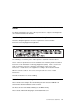
Handling Static–Sensitive Devices ATTENTION: Adapters, planars, diskette drives, and disk drives are sensitive to static electricity discharge. These devices are wrapped in antistatic bags, as shown in this illustration, to prevent this damage. Take the following precautions: If you have an antistatic wrist strap available, use it while handling the device. Do not remove the device from the antistatic bag until you are ready to install the device in the system unit.
Cover Removal 1. Unlock the cover lock and slide the drive bay cover all the way to the left. 2. Remove any media (diskettes, or CDs) from the drives. 3. Turn off all attached devices and the system unit. 4. If you have a modem or fax machine attached to the system unit, disconnect the telephone line from the wall outlet and the system unit. 5. Unplug all power cords (cables) from electrical outlets. Chapter 8.
6. Make a note of where the other cables and cords are connected to the back of the system unit; then disconnect them. 7. If you have not already done so, remove the display from the top of the system unit. 8. Unlock the cover. Then, while holding down the cover latch at the rear of the system unit, slide the cover to the rear approximately 1 inch. Grasp the cover on both sides and lift it away from the system unit.
Replacement 1. Install the cover by placing it close to the front of the system unit, as shown. Slide the cover toward the front of the system unit while holding down the cover latch. Cover L atch Cover L ock 2. Reconnect all device cables, such as the printer and display; then plug the power cords into properly grounded electrical outlets. 3. If you have a modem or fax machine attached to the system unit, reconnect the telephone line to the system unit and the wall outlet. Chapter 8.
Power Supply DANGER Do not attempt to open the covers of the power supply. Power supplies are not servicable and are to be replaced as a unit. Removal 1. Unplug all power cords (cables) from electrical outlets. 2. If you have not already done so, remove the cover as described in “Cover” on page 8-3. 3. Disconnect the power supply cables from the system board connectors and any installed drives. 4.
5. Remove the mounting screws from the rear of the power supply. 6. Remove the power supply from the system by moving it forward and then upward. Replacement Replace in reverse order, noting the following power supply cable attachments. System board power cables Diskette drive power cable Disk drive power cables Media drive power cables Chapter 8.
Cable Ties After replacing the power supply, ensure you attach cable ties at the areas designated in the following diagrams: 100mm Power Supply (Top View) P7 P5 P4 Power Supply (Top View) 25mm Max.
Power Supply (Top View) Bend cables first, then attach cable ties. 40mm P10 P12 P2 P1 P11 P9 J7 J7 J8 J2 Chapter 8.
Front Bezel and Power Switch Removal 1. If you have not already done so, remove the covers as described in “Cover” on page 8-3. 2. Do the removal procedure under “Fan and Speaker Assembly” on page 8-34. 3. Remove the media fan assembly and disconnect the media fan cable. 4. Snap off the media drive bracket attachment pin located at the left rear corner of the media drive bracket. 5.
6. All of the latches attaching the front bezel to the chassis are now accessible just inside the front of the system unit. Release these latches and pull the front bezel away from the chassis. 7. To remove the power switch, remove the two screws which secure it to the chassis, then disconnect the power switch cable from the system board. Replacement 1. Connect the power switch cable to the system board. 2. Fasten the power switch to the chassis with the two mounting screws. 3.
Media Fan Removal 1. If you have not already done so, remove the covers as described in “Cover” on page 8-3. 2. Disconnect the media fan power cable. 3. Loosen the three screws which secure the media fan assembly to the side of the media drive bracket. 4. Remove the media fan assembly. Replacement 1. Place the media fan assembly into position. 2. Secure the media fan assembly to the side of the media drive bracket with the three screws removed earlier. 3.
Internal Media Drives Notes: 1. If you have not already done so, disconnect the power cord and remove the covers as described in “Cover” on page 8-3. 2. If you are removing a CD-ROM drive refer to “Laser Safety Information” on page xii. Disk and media drives are installed in drive bays shown below. Use the following SCSI cable routing table to ensure all cables are reattached correctly. Chapter 8.
SCSI Cable System Location Cable Notes Connector 1 System Board, J4 Between Connectors 1 and 2, route over power supply, not under CD-ROM. Connector 2 Bay 2, CD-ROM Connector 3 Bay 3, Lower Media Connector 4 Bay 4, Uppser DASD Connector 5 Bay 5, Lower DASD Connector 6 System Board, J33 If empty, route extra cable through clamp above power supply. If empty, route extra cable through clamp above power supply. Diskette Drive Removal 1.
Media Drive in Bay 2 or 3 Removal 1. Remove the disk drive bracket assembly from the system unit and carefully place it on top of the power supply. 2. Remove the media fan assembly and disconnect the media fan cable. Chapter 8.
3. Snap off the media drive bracket attachment pin located at the left rear corner of the media drive bracket. 4. Remove the screw which secures the media drive bracket to the side of the chassis, then remove the media drive bracket assembly. 5. Remove the screws which secure the media or disk drive within the media drive bracket.
6. If you are removing a 3.5-inch disk drive, remove the screws which secure the disk drive mounting brackets to the disk drive. Note: The screws which secure disk drive mounting brackets to a disk drive are not the same as those used in the the rest of the assembly. Be sure to retain these screws in order to attach the disk drive mounting brackets on the replacement disk drive. Replacement: To replace, perform the removal steps in the reverse order.
Media Drive in Bay 4 or 5 Removal 1. Remove the disk drive bracket assembly from the system unit. 2. Unplug the power and signal cables from the back of the disk drive or drives. 3. Remove the screws which secure the disk drive to the disk drive bracket. Replacement: To replace, perform the removal steps in the reverse order. Be sure to match the SCSI addresses of the replacement disk drives with those of the removed disk drives.
Adapter Removal 1. If you have not already done so, remove the covers as described in “Cover” on page 8-3. 2. Note the location of the adapter you are removing. 3. Remove the expansion-slot screw for the adapter; then grasp the adapter and pull it free from the socket. Riser Adapter 4. If you are not replacing the adapter in this slot, install an expansion-slot cover into the empty expansion slot. Screw Screw Expansion-Slot Cover Replacement Replace in reverse order. Chapter 8.
Memory Modules Removal 1. Locate the memory-module connectors. To locate the six memory-module slots in the Model 140, use the following figure. To locate the four memory-module slots in the Model 150, use the following figure.
The following figure shows the location of the eight memory-module slots in the Model 240. 2. Remove any adapters that are blocking the memory-module connectors (see “Adapter” on page 8-19) 3. Remove the memory module by first pushing out the locking tabs, then carefully pulling upward on the memory module. Chapter 8.
4. Store any memory modules you are no longer using in a static-protective package. 5. Install any adapters you removed into their original connectors. If you need further information on installing adapters, see “Adapter” on page 8-19 Replacement Note: When installing memory module, install the new modules into the first available connector, starting at slot A (DIMM 0). Memory modules for the Model 240 must be installed in identical pairs (size and speed). 1.
Attention: Inserting the memory module at an angle may cause damage. 3. Inspect each memory module and ensure the gold connector is fully inserted in the socket. 4. Reinstall any adapters you removed into their original connectors. (If you need further information for installing adapters, see “Adapter” on page 8-19). Chapter 8.
Processor Card (for the Model 240) Removal 1. If you have not already done so, remove the covers as described in “Cover” on page 8-3. 2. Do the removal procedure under “Adapter” on page 8-19 as necessary. 3. Remove the screw that holds the air duct to the system board. 4. Spread the arms on the air duct and remove it from the system.
5. Push down the latches on the processor card connector to release the processor card, and lift the card straight up and out of the system unit. Replacement Replace in reverse order. Note: If more than one processor card is installed, both must be of the same speed and type. Notes: 1. Do not push on the heatsink while installing or removing a processor card. This could damage the processor. 2. Make sure to push down on the processor card until the latch tabs lock the processor card in place. Chapter 8.
L2 Cache Card (for Model 140 Only) Removal 1. Remove the disk drive bracket assembly from the system unit and carefully place it on top of the power supply.
2. Locate the L2 cache connector on the system board. 3. Gently pull upward on the L2 cache card, remove it from the system unit, and store it in a safe place. Replacement Replace in the reverse order. Chapter 8.
System Board Removal 1. If you have not already done so, remove the covers as described in “Cover” on page 8-3. 2. Do the removal procedure under “Adapter” on page 8-19. 3. Do the removal procedure under “Riser Card” on page 8-31. 4. Disconnect all cables from the system board. 5. Do the removal procedure under “Memory Modules” on page 8-20. 6. Do the removal procedure under “Processor Card (for the Model 240)” on page 8-24. 7. Remove the screws from the system board. 8.
Replacement Replace in reverse order. Notes: 1. The jumpers on the new system board should be set to match the board being replaced. 2. Licensed programs frequently rely on network configuration or system board information to authorize program use. Notify the system owner that new keys for licensed programs may be required. 3. The network administrator must be notified so that the client IP addresses used by the server may be changed. 4.
For the Model 150, note the following cables must be reattached.
Riser Card Removal 1. If you have not already done so, remove the covers as described in “Cover” on page 8-3. 2. Remove all adapters; see “Adapter” on page 8-19. 3. Remove the drive bracket assembly and carefully lay it on the power supply. 4. Disconnect all cables attached to the riser card. Chapter 8.
5. Pull the riser card straight up and out of the system unit. (The Model 240 is shown in the following illustration.) Replacement Replace in reverse order.
I/O Panel Removal 1. If you have not already done so, remove the covers as described in “Cover” on page 8-3. 2. Disconnect the following cables from the system board: Serial Port 1 Serial Port 2 Tablet Port (2 connectors in some Model 140 systems) Ethernet AUI 3. Remove the screw securing the I/O panel to the rear of the chassis. Replacement Replace in the reverse order.
Fan and Speaker Assembly Removal 1. Do the cover removal procedure in “Cover” on page 8-3. 2. For the Model 240: Remove the screw that holds the air duct to the system board. Spread the arms on the air duct enough to disengage them from the mounting pins and remove it from the system unit. 3. Do the removal procedure under “Adapter” on page 8-19 if any installed adapters are long enough to interfere with the fan and speaker assembly.
4. For the Model 240, do the procedure in “Processor Card (for the Model 240)” on page 8-24. 5. Remove the drive bracket assembly and carefully lay it on top of the power supply. 6. Disconnect the fan and speaker assembly cables from the system board. 7. Starting with the latch on the right side of the fan and speaker assembly, press the latches to release the fan and speaker assembly and lift it up and out of the system unit. Replacement Replace in reverse order. Chapter 8.
Battery CAUTION: A lithium battery can cause fire, explosion, or a severe burn. Do not recharge, disassemble, heat above 100°C (212°F), solder directly to the cell, incinerate, or expose cell contents to water. Keep away from children. Replace only with the part number specified for your system. Use of another battery may present a risk of fire or explosion. The battery connector is polarized; do not attempt to reverse the polarity. Dispose of the battery according to local regulations. Removal 1.
b. The following figure shows the location of the battery in the Model 140 and Model 150. c. Remove the battery as shown. 3. For the Model 240. Chapter 8.
a. If adapters must be removed in order to reach the battery, refer to “Adapter” on page 8-19. b. Remove the battery as shown. Replacement Install the new battery in the reverse order. Note: Skin oils can cause corrosion and loss of battery contact if left on the battery for long periods of time. Using a paper tissue when changing the battery minimizes skin contact with the battery and can preserve proper battery function.
Chapter 9. Parts Information Chapter 9.
System Unit 17 18 15 12 16 19 14 13 20 21 12 22 11 23 10 9 24 25 8 26 7 27 6 4 28 3 29 2 5 1 9-2 7043 43P Series Service Guide 30
Index Number Model 140 Model 150 Model 240 Units Per Assy Description 1 2 3 4 5 6 7 8 9 10 11 12 13 14 15 11H6764 33G3907 73H0438 73H0437 73H0436 94H0550 88G2411 07L6776 40H7584 93H1819 n/a Note 1 27F4212 Note 2 12H0649 Note 1 11H6764 33G3907 73H0438 73H0437 73H0436 94H0550 88G2411 07L6776 93H1820 93H1819 11H9747 Note 1 27F4212 Note 2 12H0649 Note 1 1 14 1 1 1 1 1 1 1 1 1 1 25-48 1-2 1 1 Power Button Screw Power Switch Assembly Power-On LED and Cable Disk Activity LED and Cable Logo Operator Panel
System Board, Cables, and Accessories 9-4 7043 43P Series Service Guide
Index Number FRU Number Units Per Assy Description 1 93H7142 93H7143 93H6023 93H9334 07L8446 11H7516 27F4212 39H8697 11H7517 1 1 1 1 1 1 6 1 1 93H5163 1 75H5462 75H5463 42H2772 19L1808 93H6823 19L1809 93H6822 29L3302 93H1821 92F2565 73H0435 1 1 1-6 2-8 1-6 2-8 1-6 2-8 1-4 1-6 1-4 2-8 1-4 1 1 1 System Board 166-MHz (Model 140) System Board 200-MHz (Model 140) System Board 233-MHz (Model 140) System Board 332-MHz (Model 140) System Board (Model 150) System Board (Model 240) Screw Hex Standoff 166M
Keyboard and Mouse 9-6 7043 43P Series Service Guide
Index Number FRU Number (Model 140 & Model 240) FRU Number (Black) Units Per Assy Description 1 8131596 1391414 1391526 64F7707 07L9451 07L9453 07L9452 07L9450 1 1 1 1 1399583 82G3280 07L9454 07L9447 07L9448 07L9481 07L9455 07L9456 07L9457 07L9458 07L9459 07L9460 07L9461 07L9462 07L9463 07L9464 07L9480 07L9482 07L9449 1 1 1 1 1 1 1 1 1 1 1 1 1 1 2 1 1 1393286 8125409 1391406 82G3278 93H8153 07L9465 07L9466 07L9467 07L9468 07L9469 07L9470 07L9471 07L9472 07L9473 07L9474 07L9483 07L9475 07L9476 0
Keyboards and Mouse - All Models Index Number FRU Part Number Units Per Assy Description 1 93H8120 93H8121 93H8122 93H8123 93H8124 93H8125 93H8126 93H8127 93H8128 93H8129 93H8130 93H8131 93H8132 93H8133 93H8134 93H8135 93H8136 93H8137 93H8138 93H8139 93H8140 93H8141 93H8142 93H8143 93H8144 93H8145 93H8146 93H8147 93H8148 93H8149 93H8150 93H8151 93H8152 93H8153 93H8154 93H8155 93H8156 93H8157 76H5084 1 1 1 1 1 1 1 1 1 1 1 1 1 1 1 1 1 1 1 1 1 1 1 1 1 1 1 1 1 1 1 1 1 1 1 1 1 1 1 Keyboard, 101 United St
Power Cables 1 2 5 8 6 9 4 3 7 10 11 Index Part Number Country 1 1838574 Bahamas, Barbados, Bolivia, Brazil, Canada, Costa Rica, Dominican Republic, El Salvador, Ecuador, Guatemala, Guyana, Haiti, Honduras, Jamaica, Japan, Netherlands Antilles, Panama, Peru, Philippines, Taiwan, Thailand, Trinidad, Tobago, U.S.A.
Index Part Number Country 7 14F0033 Bahrain, Bermuda, Brunei, Channel Islands, Cyprus, Ghana, Hong Kong, India, Iraq, Ireland, Jordan, Kenya, Kuwait, Malawi, Malaysia, Nigeria, Oman, People's Republic of China, Qatar, Sierra Leone, Singapore, Tanzania, Uganda, United Arab Emirates (Dubai), United Kingdom, Zambia 8 14F0051 Liechtenstein, Switzerland 9 14F0069 Chile, Ethiopia, Italy 10 14F0087 Israel 11 6952291 Paraguay, Colombia, Uruguay 9-10 7043 43P Series Service Guide
Appendix A. Interpreting Firmware Error Codes The error code is an 8-character (4-byte) hexadecimal code produced by firmware to identify the potential failing function or FRU in a system. It consists of 5 source code characters and 3 reason code characters. Individual characters within the error code have specific field definitions, as defined in the following tables. Table A-1 and Table A-2. Table A-1.
Table A-2 (Page 2 of 2). Service Reference Code Field Descriptions Field Description R2 - R3 Device/FRU unique failure reason codes. Table A-3 (Page 1 of 3). Current PCI 2.1 Class Code Definition PCI Base Class (lower nibble) S2 PCI Sub-Class S3 -S4 Description Devices that were built before the class code field was defined. 0 00 All currently implemented devices except VGA-compatible devices.
Table A-3 (Page 2 of 3). Current PCI 2.
Table A-3 (Page 3 of 3). Current PCI 2.1 Class Code Definition Serial bus controllers C 00 FireWire (IEEE 1394) 01 ACCESS.bus 02 Serial Storage Architecture (SSA) 03 Universal Serial Bus (USB) 04 Fibre channel Table A-4 (Page 1 of 2).
Table A-4 (Page 2 of 2).
A-6 7043 43P Series Service Guide
Index A H about this book xv adapter removal 8-19 AIX location codes 5-4 audio ports 1-2 hard disk drive in-use light 1-1 headphone connector, CD-ROM headphone port 1-2 I B index, error code to FRU 3-2 installing cover 8-5 memory modules 8-22 battery disposal, recycling xiii boot list 6-1 bus SRN to FRU Table 4-11 K C CD-ROM eject button 1-1 command line, open firmware cover installation 8-5 cover lock 8-3 1-1 7-44 D devices, startup 7-9 diskette eject button 1-1 E emergency eject, CD-ROM 1-1
microphone port 1-2 minimum configuration Map 2-21 O open firmware command line operator panel display 1-1 ordering publications xv, xvi 7-44 P parallel port 1-2 part numbers publications xvi parts 9-8 keyboard 9-8 PD bits 4-13 physical location codes 5-1 POST error codes 3-2 power MAP 2-15 power switch, location 1-1 power-on light 1-1 preface xv problem determination MAP 2-7 product disposal xiii publications ordering xv, xvi Q quick entry MAP 2-2 R recycling xiii related publications reset button 1
IBM Part Number: 08L0664 ð8Lð664 Printed in the United States of America on recycled paper containing 10% recovered post-consumer fiber.