S544-5361-01 IBM Network Color Printer: Operator’s Guide Quick Start Task Requesting service Ordering features and supplies Choosing paper Storing paper Handling transparencies Loading paper Loading transparencies Replacing a toner cartridge Diagnosing problems Clearing paper jams Where to Look page xiii page 1–4 page 2–2 page 2–5 page 2–6 page 3–2 page 3–9 page 5–4 page 6–2 page 6–3
NOTE Before using this information and the product it supports, be sure to read the general information under “Notices” on page vii. Second Edition (June 1996) This edition applies to the IBM Network Color Printer:Operator’s Guide. This publication may contain references to, or information about, IBM products (machines or programs) or services that are not announced in your country.
Table of Contents Table of Contents. . . . . . . . . . . . . . . . . . . . . . . . . . . . . . . . . . . . . . . . . . . . . . . . . . . . . . . . . . . . iii Notices . . . . . . . . . . . . . . . . . . . . . . . . . . . . . . . . . . . . . . . . . . . . . . . . . . . . . . . . . . . . . . . . . . . vii Trademarks . . . . . . . . . . . . . . . . . . . . . . . . . . . . . . . . . . . . . . . . . . . . . . . vii Communications Statements . . . . . . . . . . . . . . . . . . . . . . . . . . . . . . . . .
Chapter 2. Choosing and Storing Paper and Transparencies . . . . . . . . . . . . . . . . . . . Choosing Paper . . . . . . . . . . . . . . . . . . . . . . . . . . . . . . . . . . . . . . . . . . Paper You Should Use . . . . . . . . . . . . . . . . . . . . . . . . . . . . . . . . . . . Paper You Should Not Use . . . . . . . . . . . . . . . . . . . . . . . . . . . . . . . Understanding the Printable Area on a Page . . . . . . . . . . . . . . . . . . . . Handling and Storing Paper and Transparencies . . . . .
Setting the Power Savings Mode . . . . . . . . . . . . . . . . . . . . . . . . . . Using the Language Menu . . . . . . . . . . . . . . . . . . . . . . . . . . . . . . . . . Changing the Language . . . . . . . . . . . . . . . . . . . . . . . . . . . . . . . . . Language Menu Settings . . . . . . . . . . . . . . . . . . . . . . . . . . . . . . . . 4–23 4–24 4–24 4–24 Chapter 5. Replacing Supplies . . . . . . . . . . . . . . . . . . . . . . . . . . . . . . . . . . . . . . . . . . . .
Understanding Status Messages . . . . . . . . . . . . . . . . . . . . . . . . . . . 7–7 Understanding Operator Error Messages. . . . . . . . . . . . . . . . . . . . . 7–8 Chapter 8. Maintaining the Printer . . . . . . . . . . . . . . . . . . . . . . . . . . . . . . . . . . . . . . . . . 8–1 Cleaning the Outside of the Printer . . . . . . . . . . . . . . . . . . . . . . . . . . . 8–2 Cleaning the Paper Path . . . . . . . . . . . . . . . . . . . . . . . . . . . . . . . . . . .
Notices References in this publication to IBM products, programs, or services do not imply that IBM intends to make these available in all countries in which IBM operates. Any reference to an IBM licensed product, program, or service is not intended to state or imply that only IBM’s product, program, or service may be used. Any functionally equivalent product, program, or service that does not infringe any of IBM’s intellectual property rights may be used instead of the IBM product.
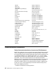
Apple Apple logo AppleTalk ATM (Adobe Type Manager) AXIS EPS (Encapsulated PostScript) Ethernet EtherTalk Fiery Fiery driven Fiery XJ Fiery logo IPX (Internetwork Packet Exchange) ITC Advant Garde Gothic ITC Bookman ITC Zapf Chancery ITC Zapf Dingbat Macintosh Microsoft Mylar Netware Novell Pagemaker PANTONE PostScript Quark XPress QuickDraw TrueType Univers UNIX Windows Apple Computer Inc. Apple Computer Inc. Apple Computer Inc. Adobe Systems Inc. AXIS Communication, Inc.
• Increase the separation between the equipment and receiver. • Connect the equipment into an outlet on a circuit different from that to which the receiver is connected. • Consult an IBM authorized dealer or service representative for help. Properly shielded and grounded cables and connectors (IBM partnumber 68X3949 or its equivalent for PC parallel) must be used in order to meet FCC emission limits. Proper cables and connectors are available from IBM authorized dealers.
x IBM Network Color Printer Operator’s Guide
Preface This publication tells you how to perform tasks such as loading paper, loading transparencies, removing paper jams, changing paper size, and other similar tasks. Audience This publication is intended for a key operator who maintains the printer and orders supplies, and for all users who replace supplies and who submit print jobs to this printer.
Terminology Common Phrases This guide refers to the IBM Network Color Printer as the printer. Additionally, the Network Print Server feature is referred to as the NPS. Paper Input and Output Receptacles Input receptacles are called trays, such as tray 1, tray 2, and auxiliary tray. Output receptacles are called output trays. Safety Notices There are 3 levels of safety notices: • DANGER calls attention to a situation that is potentially extremely hazardous to people.
Laser Safety This printer complies with the performance standards set the by U.S. Food and Drug Administration for a Class 1 Laser Product. This means that the printer belongs to a class of laser products that does not produce hazardous laser radiation in a customer access area. This classification was accomplished by providing the necessary protective housing and scanning safeguards to ensure that laser radiation is inaccessible or within Class 1 limits.
• You may call for service free of charge during the printer’s warranty period. • You can obtain service after the warranty period has expired if you sign a service contract agreement with an authorized service provider. • You also can obtain service on a billable-per-call basis after the warranty period has expired. • Please have your service contract information available when you call.
Chapter 1. Welcome to the IBM Network Color Printer This chapter tells you about the printer’s features and parts. This chapter also lists supplies that you can order for the printer and tells you how to turn the printer on and off. This chapter covers the following topics: Introducing the Printer . . . . . . . . . . . . . . . . . . . . . . . . . . . . . . . . . . . . . 1–2 General Description . . . . . . . . . . . . . . . . . . . . . . . . . . . . . . . . . . . . . 1–2 Highlights . . . . . . . . . . . .
Introducing the Printer This section gives you a general overview of the printer, including highlights and optional features. General Description The IBM Network Color Printer is a midrange workgroup printer. It can produce single-sided black and white prints at a rate of up to 12 impressions per minute (IPM) and full-color prints at a rate of up to 3 IPM. The printer has a cyan-magenta-yellow-black (CMYK), full-color laser processor that prints 16 gray levels per color.
Optional Features The printer has several optional features. See the following sections for more on these features. Contact your IBM marketing representative or authorized service dealer for information about the following optional features and how to order them. Optional Tray 2 Paper Feeder (Feature Code 4501) This feature includes a paper feeder unit, a universal paper cassette, and 2 locking pins to fasten the paper feeder unit to the printer body.
Ordering Supplies This section lists the supplies you can order for the printer and gives you the telephone number you should use when ordering supplies. To order supplies for the printer, call 1-888-IBM-PRINT in the U.S. and Canada. You may also contact your IBM marketing representative for information about how to order supplies. The following table lists the supplies you can order for the printer.
Supplies Item Part Number Transparencies— 50-Sheet Letter Pack 63H2046 Transparencies— Ten 50-Sheet Letter Packs 63H2047 Transparencies— 50-Sheet A4 Pack 63H2048 Transparencies— Ten 50-Sheet A4 Packs 63H2049 Description IBM recommends that you use only IBM transparencies for the best printing results. Relocation Kit 52H0799 The relocation kit contains the packaging, boxing, and instructions that you need to safely move the printer a substantial distance.
Identifying Printer Parts and Controls This section helps you identify each part of the printer. The illustrations that follow show the printer’s parts and controls and what they are used for. Front and Right Sides Shown below are the parts of the printer that you access from the front and right sides. Fuser oil bottle (cover open) The fuser oil bottle supplies the fuser oil that is applied to the fuser rollers during the printing process.
Release latches The release latches release the catches on the fuser access and feeder access doors so that you can do maintenance tasks or clear paper jams. Fuser access door (closed) When opened, this door gives you access to the paper output area so that you can remove jammed paper and replace the fuser. Side output tray (faceup) (open) When opened, the side output tray receives printouts faceup. When the side output tray is closed, the top output tray receives printouts facedown.
Top output tray (facedown) (open) This tray holds approximately 100 sheets of plain paper at 80 g/m2. Wire cleaner (stored inside the printer) The wire cleaner is used to clean the separation corona wire (inside the separation corona unit) and the window of the density detection sensor. The wire cleaner looks like this: Separation corona unit The separation corona unit helps separate the printout from the photoconductor drum cartridge during the printing process.
Back and Left Sides Shown below are the parts of the printer that you access from the back and left sides of the printer. and Air ventilation slots These slots prevent overheating and ensure that the printer works reliably. Do not block these air ventilation slots. Air filter holder This holder contains the air filter and gives you access to the carbon filter.
Inside the Front Door Shown below are the parts of the printer that are inside the front door of the printer. Fuser oil bottle cover (closed) When closed, this cover locks the fuser oil bottle securely to the printer. Transfer drum knob When turned, this knob rotates the transfer drum so that you can remove jammed paper (the release handle must be down).
Photoconductor drum cartridge door handle When raised, this handle opens the photoconductor drum cartridge door so that you can install or replace a photoconductor drum cartridge. Turret rotation knob When pushed and turned, this knob rotates the turret so that you can replace the toner cartridge. Serial number label (see below) The serial number label identifies the printer. You see the serial number label when you open the feeder access door. Do not remove this label. Chapter 1.
Identifying Parts on the Density Control Panel This section helps you identify each part of the density control panel. You rarely will need to use the density control panel. See “Adjusting the Color Density” on page 6–22 for some task-specific information. The density control panel is on the back of the printer. Shown below are the parts of the density control panel. TEST PRINT push button Press the TEST PRINT push button to print a test pattern that can be used to check the result of a density change.
Turning the Printer On and Off This section tells you how to turn the printer on and off. When you turn the printer and its connected devices on or off, follow the procedure below. Attention: Never turn the printer on without a fuser oil bottle and a used toner bottle installed. Turning the Printer On Use the following procedure to turn on power to the printer. 1. Turn on any devices connected to the printer (such as a SCSI hard drive or CD ROM). 2.
Resetting the Printer Use the following procedure to reset the printer. 1. Turn off the printer. 2. Wait 5 seconds or more before you turn the printer on again. 3. Turn on the printer.
Chapter 2. Choosing and Storing Paper and Transparencies This chapter tells you what paper to use in the printer and how to store and handle paper and transparencies. This chapter covers the following topics: Choosing Paper . . . . . . . . . . . . . . . . . . . . . . . . . . . . . . . . . . . . . . . . . . Paper You Should Use . . . . . . . . . . . . . . . . . . . . . . . . . . . . . . . . . . . Paper You Should Not Use . . . . . . . . . . . . . . . . . . . . . . . . . . . . . . .
Choosing Paper This section gives you the specifications for paper you should use and paper you should not use in the printer. Using a good quality of paper ensures the best print quality, prevents paper jams, and reduces the amount of maintenance needed. Note: Not all print media can be used in this printer. Always print a few pages before you buy a large quantity of paper. IBM recommends that you use IBM paper for the best printing results. Envelopes and labels are not recommended.
During the fusing process, paper is exposed to high temperatures. Do not use paper that is affected by high temperatures. Examples are: • Thermal paper • Paper whose surface cannot hold the toner at high temperature • Preprinted paper containing ink that deteriorates at high temperatures (for example, invoices and preprinted forms) • Adhesive paper Attention: Paper that changes or deteriorates at high temperatures can damage this printer.
Understanding the Printable Area on a Page This section shows you the area of a page on which you can print. The shaded part of the figure below shows you the printable area on a sheet of paper or transparency. The table that follows the figure gives you the measurements for the border width of different sizes of paper. Direction of Feed Border Width Size 2–4 A B C D Letter, legal, A4, and JIS B5 (mm) 10.0 5.0 5.0 5.0 Letter, legal, A4, and JIS B5 (inches) 0.4 0.2 0.2 0.
Handling and Storing Paper and Transparencies This section tells you how to handle paper, store it, store printouts, and handle transparencies for the best print quality. Handling and Storing Paper Paper that you handle and store correctly is in the best shape for printing. Follow these guidelines for handling and storing paper. • Store unused paper in its wrapping to protect the paper against humidity. • Do not store the paper directly on the floor. The floor is usually humid.
Handling Transparencies IBM recommends that you use IBM transparencies for the best printing quality. Follow these guidelines for handling transparencies: • Use IBM color transparencies only with IBM color printers. These transparencies are designed exclusively for color laser printers. • Pick up each printed transparency as soon as it comes out of the printer to prevent the next sheet from jamming. • Make sure no fuser oil gets on a transparency.
Chapter 3. Loading Paper and Transparencies This chapter tells you how to load paper into the printer, how to choose the tray for output, and how to know when to add paper. This chapter covers the following topics: Loading Paper . . . . . . . . . . . . . . . . . . . . . . . . . . . . . . . . . . . . . . . . . . . 3–2 Loading Paper in Tray 1 and Tray 2 . . . . . . . . . . . . . . . . . . . . . . . . . 3–2 Loading Paper in the Auxiliary Tray . . . . . . . . . . . . . . . . . . . . . . . . .
Loading Paper This section tells you how to load paper in tray 1, tray 2, and the auxiliary tray. Follow these guidelines when you load paper: • Make sure that the paper meets the printer’s specifications (see “Choosing Paper” on page 2–2) and that it has been in the printer environment for at least 24 hours before you use it. (This is especially important if you are in a climate with high humidity.) • Do not load transparencies in tray 1 or tray 2. Use the auxiliary tray instead.
Use the following procedure to load paper into either tray 1 or tray 2. 1. Push up the handle on the underside of the tray and pull out the tray (tray 1 is shown here). 2. Press the release button and slide the paper-width guide to the size of paper to be loaded. Release the button to lock the guide in place. Where you set the paper-width guide determines how the printer knows what size of paper is in the tray. Make sure that the paper-width-guide setting matches the size of paper to be loaded.
4. Set the paper-size indicator on the front of the tray to match the paper size you loaded (for example, LTR for letter-size paper). This helps you and others identify the size of paper in the tray. 5. Load the paper. a. Fan out small stacks of paper to lessen the chance of feeding problems. b. Put the tray on a flat surface. Then load a stack of paper into the tray with the print side facing up and the bottom edge going first into the tray.
c. Make sure the paper stack does not go above the paper-limit mark. 6. Press down on the paper so that it is anchored under the 2 retaining clips. 7. Align the tray so that it lines up with the rails inside the paper feeder. Chapter 3.
8. Press the handle on the underside of the tray upward and slide the tray all the way into the paper feeder until the tray snaps into place. The tray is now ready to supply paper. Loading Paper in the Auxiliary Tray The auxiliary tray holds approximately 100 sheets of paper at 80 g/m2. You can use letter, legal, A4, or JIS B5-size paper and letter- and A4-size transparencies. You can close the tray when it is not in use, making the printer very compact.
Loading Paper in the Auxiliary Tray Note: Make sure that the paper meets the printer’s specifications (see “Choosing Paper” on page 2–2) and that it has been in the printer environment for at least 24 hours before you use it. (This is especially important if you are in a climate with high humidity.) Use the following procedure to load paper in the auxiliary tray. 1. Adjust the paper guides to the paper size you want. 2. Tap a stack of paper on a flat surface to align its edges. 3.
4. Check that the paper stack does not go above the paper-limit mark. Avoid pressing or applying excessive force to the auxiliary tray. The auxiliary tray is now ready to supply paper. Follow these guidelines for loading paper. 1. Load the auxiliary tray with only one size of paper at a time. 2. Add paper to the auxiliary tray only when it is completely empty. Otherwise, you may cause the paper to feed incorrectly or to jam. 3.
6. Avoid setting the paper guides so loosely that there is space between the guides and the paper. 7. Align the paper in the tray so that it is straight. Loading Transparencies in the Auxiliary Tray Load transparencies only in the auxiliary tray. You can load approximately 20 sheets at a time. IBM recommends that you use only IBM transparencies for the best print quality. For ordering details, see “Ordering Supplies” on page 1–4, or contact your IBM service representative or authorized service dealer.
When you load transparencies, position each sheet so that the white positioning marker (triangle) is on the upper right side. In this position, the print side is the back side. Use the following procedure to load transparencies. 1. Adjust the paper guides to accept transparencies (letter or A4 size). 2. With the white positioning marker on the upper right side, tap a stack of transparencies on a flat surface to align its edges.
3. Before you load the transparencies, fan out small stacks of them to lessen the chance of feeding problems. Be careful not to scratch the transparency or leave fingerprints on the print sides. 4. Position each sheet so that the white positioning marker is on the upper right side and push it as far as it can go into the printer. 5. Check that you have not gone above the paper limit mark. The auxiliary tray is now ready to supply transparencies. Chapter 3.
Closing the Auxiliary Tray Use the following procedure to close the auxiliary tray. 1. Lift the end of the extension tray slightly and push it into the auxiliary tray. 2. Close the auxiliary tray.
Choosing the Paper Output Tray The printer has two methods of delivering paper. Which one you use depends on the paper type, the size of the document, or if you want your document collated. This section tells you how to use the side output tray and the top output tray. Using the Side Output Tray If the side output tray is open, printouts are delivered faceup into the tray. Use this delivery method for normal printing and when you print on heavy-weight paper.
2. Pull on the extension tray grip to pull out the tray. Closing the Side Output Tray Use the following procedure to close the side output tray. 1. Push in the extension tray. 2. Close the side output tray until it snaps into place.
Using the Top Output Tray If you want to direct printouts into the top output tray, close the side output tray. Printouts then come into the top output tray facedown and stacked in order. This is handy when you want to collate your documents. Also, if you print large jobs, use the top output tray because it holds up to 100 sheets of paper at 80 g/m2. Chapter 3.
3–16 IBM Network Color Printer Operator’s Guide
Chapter 4. Using the Operator Panel This chapter tells you how the operator panel works and how to use menus on the display panel. This chapter covers the following topics: Identifying Each Part of the Operator Panel . . . . . . . . . . . . . . . . . . . . . 4–2 Lights . . . . . . . . . . . . . . . . . . . . . . . . . . . . . . . . . . . . . . . . . . . . . . . . 4–2 Online Push Button and Light . . . . . . . . . . . . . . . . . . . . . . . . . . . . . . 4–2 Cancel Push Button . . . . . . . . . . . . . .
Identifying Each Part of the Operator Panel This section identifies the parts of the operator panel. Use the lights and push buttons on the operator panel to control the printer and to learn its status. Following is an illustration of the operator panel and a description of each of its parts. through Lights Power The Power light is green. When it is lit, the printer is on. Busy The Busy light is green. When it is lit, the printer is processing or printing a job. Attention The Attention light is yellow.
The Online light shows the status of the printer. This table tells you what each kind of Online light means. Light What it means Solid green The printer is processing or printing a job or communicating with a remote computer (for example, through the printer Spooler utility). Flashing green The printer is preparing to go offline. Off The printer is offline or is starting up. Cancel Push Button Press the Cancel push button to stop printing the current job.
Enter Use the Enter push button as shown in the following table. When you... Press the Enter push button to... See the Attention light flash but there is no error message on the display panel See 1 or more warning messages See warning messages on the display panel See the current status message See a Setup menu Choose the menu on line 2 of the display panel and access the next level of menus See a menu setting Make that setting the current one.
Canceling a Print Job This section tells you how to cancel a print job. Press the Cancel push button to cancel the job that is currently printing. If no job is printing, Cancel removes the job being processed (the oldest job). You must be online for Cancel to work.
Understanding the Menus This section tells you how to navigate and choose from the menus you see on the display panel. The menu groups, menus, and items in a menu are shown in the table below.
Navigating the Menus Use the following procedure to navigate the menus. 1. Choose the online or offline menu group by toggling the Online push button between online and offline. Use the table below to find the menu you want. Menu Group Menu Where to Find an Explanation ONLINE PRINT PAGES See “Using the Online Menu (Print Pages Menu)” on page 4–8. RUN SETUP See “Using the Offline Menus” on page 4–11. LANGUAGE See “Using the Language Menu” on page 4–24. OFFLINE 2. Press the Menu push button. 3.
Using the Online Menu (Print Pages Menu) The online menu consists of the Print Pages menu. The Print Pages menu allows you to print information stored in the printer to help solve problems and to see the printer’s configuration. The Help Map and the configuration page give you valuable information about using the printer. Print these pages and keep them near the printer.
Printing the Help Map Use the following procedure to print the Help Map. This map tells you about the operator panel, push buttons, and panel lights and lists all the menus. 1. Go to the Print Pages menu (see “Accessing the Print Pages Menu” on page 4–8). 2. When you choose the Print Pages menu, you see HELP MAP on the second line of the display panel. 3. Press the Enter push button. Several messages appear on the display panel that tell you what the printer is doing until the Help Map is printed. 4.
Printing a Test Page Use the following procedure to print a test page. This page shows you samples of color and grayscale that you can use to determine whether or not you are printing correctly from an application. The test page also shows you the printer name, printer model, color mode, print count, calibration, memory multiplier setting, color-rendering dictionary, and date and time printed. 1. Go to the Print Pages menu (see “Accessing the Print Pages Menu” on page 4–8). 2.
Using the Offline Menus Use the offline menu group to define the printer’s default settings. From the offline menu group, choose the Run Setup or Language menu. From these menus, access menus such as Printer Setup or System Setup. (See the table in “Understanding the Menus” on page 4–6.) Because some of the offline menus are for your system administrator to use, they are covered in the Administrator’s Guide.
Accessing the Offline Menus Use the following procedure to access the offline menus. 1. Check that the printer is offline (the Online light is not on). If the printer is not offline, press the Online push button. Note: If the printer is communicating with a utility when you take it offline, the printer remains in an “offline pending” state until the utility is disengaged. 2. Press the Menu push button. You see SELECT FUNCTION on the first line of the display panel. 3.
Entering a Password If your system administrator has assigned a password for the Run Setup menus, use the following procedure to enter that password. 1. When a password is required, you see ENTER PASSWORD on the display panel. Use the Menu Scrolling push buttons (↑↓) to set the first alphanumeric character of the password on the second line of the display panel. 2. Use the right Cursor Position push button (→) to advance the cursor to the next character position. 3.
Using the Printer Setup Menu Use this menu to set commonly used printer specifications such as paper size and paper source. Accessing the Printer Setup Menu Use the following procedure to access the Printer Setup menu. 1. Check that the printer is offline (the Online light is not on). If the printer is not offline, press the Online push button. 2. Press the Menu push button. You see SELECT FUNCTION on the first line of the display panel and RUN SETUP on the second line. 3. Press the Enter push button.
4. Use the Menu Scrolling push buttons (↑↓) to scroll through the available settings, TRAY 1, TRAY 2, AUXILIARY TRAY, or AUTO SELECT. If you choose AUTO SELECT and if tray 1 or tray 2 runs out of paper, the printer feeds paper from the other tray (tray 1 or tray 2) that matches the paper size in the tray that ran out. TRAY 1 is the default. 5. When you see the setting you want, press the Enter push button. 6. Press the Menu push button 3 times.
Choosing the Color Mode Note: The setting you choose here is used only for jobs that do not specify a color mode. Use the following procedure to choose whether to print color or grayscale images. 1. Go to the Printer Setup menu (see “Accessing the Printer Setup Menu” on page 4–14). 2. Use the Menu Scrolling push buttons (↑↓) to scroll through the items until you see COLOR MODE on the second line of the display panel. 3. Press the Enter push button.
6. Press the Menu push button 3 times. You see EXIT SETUP on the first line of the display panel and the default setting, NO, on the second line. 7. Press the down Menu Scrolling push button (↓) to see YES on the second line. 8. Press the Enter push button. You see SAVE CHANGES on the first line of the display panel and the default setting, YES, on the second line. Press the Enter push button to save the changes.
Choosing to Print a Start Page Use the following procedure to choose whether or not the printer prints a start page when you turn the power on. The start page shows the current date, last calibration date, color mode and printer mode, amount of memory installed in the printer, network protocols enabled, and connections enabled. 1. Go to the Printer Setup menu (see “Accessing the Printer Setup Menu” on page 4–14). 2.
Using the System Setup Menu Use the System Setup menu to change the printer name, date, and system time and to set or change the password and the Power Savings mode. The following sections tell you how to use the System Setup menu. Accessing the System Setup Menu Use the following procedure to access the System Setup menu. 1. Check that the printer is offline (the Online light is not on). If the printer is not offline, press the Online push button. 2. Press the Menu push button.
Setting the Printer Name Use the following procedure to change the name by which the printer is identified on the network. Choose a name that clearly identifies the printer to users, such as IBM 4303 Color. The default name is IBMnetcolor. 1. Access the System Setup menu (see “Accessing the System Setup Menu” on page 4–19). You see PRINTER NAME on the second line of the display panel. 2. Press the Enter push button.
5. Press the Enter push button. SYSTEM TIME moves up to the first line of the display panel and you see the system time that is stored on the printer’s clock on the second line. Enter the new time, based on the 24-hour clock, in the form HH:MM (hours:minutes) as follows: a. Use the Menu Scrolling push buttons (↑↓) to change the first number of the time on the second line of the display panel. b. Use the right Cursor Position push button (→) to advance the cursor to the next number position. c.
5. You see NEW PASSWORD on the first line of the display panel. Enter the new password as follows. The password can be any combination of letters and numbers up to 20 characters. a. Use the Menu Scrolling push buttons (↑↓) to change the first alphanumeric character of the password on the second line of the display panel. b. Use the right Cursor Position push button (→) to advance the cursor to the next character position. c. Repeat step 1 and step 2 for each character in the password. d.
Setting the Power Savings Mode Use the following procedure to set or change the Power Savings mode. The Power Savings mode allows you to set the amount of time that the printer remains idle before it changes to a low power consumption mode (Energy Star). You can set a time from 15–120 minutes in increments of 15 minutes. 1. Access the System Setup menu (see “Accessing the System Setup Menu” on page 4–19). 2.
Using the Language Menu Use the Language menu to change the language that you see on the display panel. Changing the Language Use the following procedure to change the language. 1. Check that the printer is offline (the Online light is not on). If the printer is not offline, press the Online push button. 2. Press the Menu push button. You see SELECT FUNCTION on the first line of the display panel and RUN SETUP on the second line. 3. Press the down Menu Scrolling push button (↓).
Chapter 5. Replacing Supplies This chapter tells you how to replace the printer’s toner cartridge, the used toner bottle, the fuser oil bottle, the fuser, and the photoconductor drum cartridge. It also tells you how to store and handle toner cartridges. This chapter covers the following topics: Storing and Handling Toner Cartridges . . . . . . . . . . . . . . . . . . . . . . . . 5–2 Replacing Toner Cartridges . . . . . . . . . . . . . . . . . . . . . . . . . . . . . . . . .
Storing and Handling Toner Cartridges This section tells you how to store and handle toner cartridges. Follow these instructions: • To avoid temporary problems caused by moisture, allow enough time for toner cartridges to stabilize in the printer’s environment. • Do not unseal or remove a toner cartridge from its protective package until it has reached room temperature (1–2 hours). • Do not store the cartridges where they are exposed to direct sunlight.
Ordering Supplies To order supplies for the printer, call 1-888-IBM-PRINT in the U.S. and Canada. You may also contact your IBM marketing representative for information about how to order supplies. Chapter 5.
Replacing Toner Cartridges This section guides you through the following procedures: • Removing an old toner cartridge from the printer • Installing a new one • Recycling the used one Follow these instructions when you replace a toner cartridge: • When you load a toner cartridge, make sure its color matches the color markers on the printer. The printer uses 4 color toner cartridges: cyan, magenta, yellow, and black. Each color cartridge has its own holder in the printer’s turret.
Removing the Old Cartridge Use the following procedure to remove the old toner cartridge from the printer. Attention: Be careful when you handle toner cartridges. The used toner cartridges have no seal so some toner may spill. 1. Open the front door. 2. Find the turret rotation knob. Chapter 5.
3. Use the turret rotation knob as follows: a. Push the knob in [1] and turn it clockwise about the distance between arrow [1] and arrow [2]. b. Release the knob [2]. c. Turn the knob clockwise [3]. d. When the turret is positioned to release a cartridge, the knob moves outward [4] and locks. e. When the color markers on the toner cartridge match the color markers on the turret, the toner cartridge is positioned for removal. 4.
5. Slide the cartridge out. 6. Hold the cartridge by the end with the opening seal to avoid getting your hands dirty and insert the cartridge into the protective bag that came with the new cartridge. 7. Dispose of the toner cartridge according to local regulations (see “Recycling the Used Toner Cartridge” on page 5–13). Do not shake the used cartridge. The toner might leak. Chapter 5.
Installing a New Cartridge Use the following procedure to install a new toner cartridge in the printer. 1. Find the turret rotation knob and the turret color markers in the illustration below. Because the printing process requires that the colors be applied in a specific order, the placement of each color toner cartridge in the turret is important. If you operate the printer with a toner cartridge inserted in the wrong order, you will damage the printer.
3. The turret rotation knob turns the turret so that you can insert the correct color toner cartridge. Before you insert a toner cartridge, turn the knob and notice the opening in the turret. Use the turret rotation knob as follows: a. Push the knob in [1] and turn it clockwise about the distance between arrow [1] and arrow [2]. b. Release the knob [2]. c. Turn the knob clockwise [3]. Notice the rotation of the color markers in the turret opening. d.
5. Hold the cartridge as shown below. Do not hold the cartridge so tightly that the tabs on the end of the cartridge contact your hand. Pressing the tabs can partially open the cover of the developing cylinder and damage the printer. Slowly move each end up and down five or six times to distribute the toner. (Do not do this with a used or an unsealed toner cartridge.) 6. Remove the 2 protective tapes from the toner cartridge. 7. To remove the sealing tape, put the toner cartridge on a level surface.
Attention: Do not install a toner cartridge into the printer unless its developing cylinder cover is latched closed. 8. On the other end of the cartridge there is a small tab and an arrow [1]. Make sure that the tab [3] is fully seated in the notch [4]. Do one of the following: – If the tab is fully seated, go to step 9. – If the tab is not fully seated, hold the cartridge and use a pulling motion with your other hand to rotate the developing cover in the direction of the arrow [2].
Attention: Make sure that you insert the toner cartridge that matches the color markers in the turret opening. 9. Hold the toner cartridge with the arrow [2] up and pointing toward the printer. Using the arrow [1] on the printer’s frame as a guide, slide the toner cartridge into the printer until it locks in place. You may have to push firmly on the cartridge to lock it into place. 10. When the toner cartridge is locked in place, the surfaces [1] and [2] are even. 11.
Recycling the Used Toner Cartridge Use the following procedure to recycle the used toner cartridge. 1. Find the box that the new toner cartridge came in and the Clean Earth Campaign instruction sheet and shipping label provided inside the box. 2. Put the used toner cartridge in the foil bag that the new cartridge came in. 3. Put the used toner cartridge in the box that the new cartridge came in. 4. Seal the box. 5.
Replacing the Used Toner Bottle This section tells you how to replace the used toner bottle. When you see the REPLACE USED TONER BOTTLE message on the display panel, use the following procedure to replace the used toner bottle. 1. Open the front door. 2. Push down on the release handle. 3. Open the photoconductor drum cover.
4. Remove the used toner bottle. 5. Seal the used toner bottle. 6. With the opening in the bottle facing the printer, attach the new used toner bottle [1] to the photoconductor drum cartridge. 7. Lower the photoconductor drum cover [2] to the closed position. 8. Raise the release handle [3] to the operating position. 9. Close the front door. <2-13> CAUTION: Do not dispose of toner or toner containers in fire. Dispose of these in accordance with local regulations. Chapter 5.
Replacing the Fuser Oil Bottle This section tells you how to replace the fuser oil bottle. Fuser oil is used in the final stage of the printing process. When the oil level is low or when you see the FUSER OIL LOW message on the display panel, replace the fuser oil bottle with a new one using the instructions that follow. <2-4> CAUTION: If spilled, fuser oil causes hazardous surfaces; prevent anyone from entering the area until the surface is clean.
Installing the New Fuser Oil Bottle Use the following procedure to install the new fuser oil bottle. Attention: Do not shake the fuser oil bottle. Oil can spill out. 1. Peel off the seal from the new fuser oil bottle. 2. Turn the oil bottle upside down. Hold the oil bottle with its label facing out and put the bottle in the oil bottle holder. Chapter 5.
3. Align the bottle with the bottle holder. Firmly push down [1] on the bottle until it locks into place. 4. Raise the fuser oil bottle cover [2]. 5. Close the front door. 6. Print a configuration page (see “Printing a Configuration Page” on page 4–9) and note the print count that it reports. Record this information on your Supplies Replacement Log, shown in Appendix B.
Replacing the Fuser This section shows you how to • Prepare the fuser and work area before beginning • Remove the unused oil from the printer oil bottle holder (fuser oil-supply) • Remove the used fuser • Install a new fuser • Return the unused oil and add a new bottle of oil to the printer You do not replace the fuser often. It is designed to fuse approximately 60 000 prints, depending on your application.
3. Choose a level work area on which to put the used fuser, the new fuser, and the fuser oil. Put absorbent towels under the front of the printer and on the work area in case a few drops of fuser oil spill. Keep towels available in case you need to clean your tools. 4. Make sure that the printer is stable. If the printer is on the printer stand, make sure that the casters underneath the stand are locked. Unpacking the New Fuser Use the following procedure to unpack the new fuser from the shipping box. 1.
Removing the Fuser Oil from the Printer Use the following procedure to remove the fuser oil from the printer. <2-6> CAUTION: High temperature; Switch off printer power and allow at least 15 minutes for parts in this area to cool before handling. 1. Open the fuser access door on the upper right side of the printer. <2-4> CAUTION: If spilled, fuser oil causes hazardous surfaces. Prevent anyone from entering the area until the surface is clean. 2. Lower the fuser oil bottle cover [1].
4. Open the oil recycle bottle and remove the inner seal. 5. Put the oil recycle bottle on a towel on a level surface near the printer. 6. Use the oil removal tool to remove the fuser oil from the oil bottle holder as follows: a. Push the top of the oil removal tool all the way down. Insert the pointed end of the oil removal tool into the oil supply in the oil bottle holder. Release the pressure on the oil removal tool and allow the oil to flow into it. b. Be careful not to spill any oil.
7. Use the fuser jam-release lever to pump the remaining oil from the fuser into the oil bottle holder. You will need to pump the lever approximately 50 times. 8. Repeat step 6 and step 7 three or four times until you have removed most of the oil from the fuser. 9. Replace the inner seal (see page 5–22) on the oil recycle bottle and cap the bottle. 10. Clean the oil removal tool with a towel and store it in the box in which it was shipped. Chapter 5.
Removing the Fuser Access Door Use the following procedure to remove the fuser access door from the printer. Attention: When you release the fuser access door strap, the door is free to swing down and may fall to the floor. Hold the door when you release the door strap. 1. Open the feeder access door on the lower right side of the printer. 2. The strap of the fuser access door is attached to the upper locking tab on the printer frame. Release the strap this way: a. Push the upper locking tab down [1]. b.
3. Slide the fuser access door to the left and rotate it down until the tab on the right pivot aligns with the cutout in the right bracket [1]. Slide the door to the left again and out of the brackets. Chapter 5.
Removing the Used Fuser Use the following procedure to remove the used fuser from the printer. 1. Loosen the 2 fuser screws that hold the fuser to the printer frame. These screws do not come out of the fuser. The fuser is not yet free. It is held by the fuser slide plate. 2. Use the 2 black pull knobs on the fuser to carefully pull the fuser and the fuser slide plate out approximately 25 cm (10 inches) until the fuser slide plate stops moving. The fuser slide plate continues to support the fuser. 3.
Installing the New Fuser Use the following procedure to install the new fuser in the printer. 1. Use the green fuser handholds to put the new fuser on the sliding plate with the oil bottle holder positioned to the front of the printer. Position the 2 blue locating guides on the plate in the locating holes in the bottom of the fuser. 2. Use even pressure on the 2 black pull knobs (see step 2 on page 5–26) to slide the fuser firmly into place.
4. Pivot the orange shipping spacers up and pull them straight out of the fuser. Discard the shipping spacers.
Replacing the Fuser Access Door Use the following procedure to replace the fuser access door on the printer. 1. Make sure that the feeder access door is open. 2. Hold the fuser access door with the top edge pointing down and align the 2 pivots on the door with the 2 brackets on the frame (the door pivot on the right has a tab that aligns with the cutout [1] in the right bracket). Slide the door to the right and rotate it up. 3. Grasp the tab at the top of the strap on the fuser access door [1].
Filling the New Fuser Unit with Fuser Oil Use the following procedure to fill the new fuser unit with fuser oil. <2-4> CAUTION: If spilled, fuser oil causes hazardous surfaces. Prevent anyone from entering the area until the surface is clean. 1. Open the oil recycle bottle and slowly pour the oil saved from the used fuser unit into the oil bottle holder of the new fuser unit. 2. Replace the inner seal (see step 4 on page 5–22) and close the oil recycle bottle.
6. Raise the fuser oil bottle cover [2]. 7. Close the fuser access door and the feeder access door. 8. Close the front door. Printing Test Pages Use the following procedure to print test pages to determine if you have correctly installed the new fuser. 1. Turn on the printer. The printer fuser takes approximately 5 minutes to warm up if it is cold when you turn the printer on. While the printer is warming up, it runs a power-on self-test (POST). The POST checks to see if the printer is working correctly.
2. Print several test pages as described in “Printing a Test Page” on page 4–10. 3. Check that the toner is completely fused onto the paper by gently rubbing the printout. If the toner smears or comes off, see “Correcting Print Quality Problems” on page 6–13. 4. Print a configuration page (see “Printing a Configuration Page” on page 4–9) and note the print count that it reports. Record this information on your Supplies Replacement Log, shown in Appendix B.
Replacing the Photoconductor Drum Cartridge This section tells you how to replace the photoconductor drum cartridge and clean the separation corona wire. If you see black vertical streaks or toner spots on printouts, it is time to replace the photoconductor drum cartridge. If you see the REPLACE DRUM TO ENSURE QUALITY message on the display panel, replace the cartridge immediately, using the procedure below. Note: When you replace the photoconductor drum cartridge, replace it with a new cartridge.
3. Open the photoconductor drum cover. 4. Remove the used toner bottle. Attention: Do not remove the used toner from the toner bottle or reuse it. 5. Seal the used toner bottle and put it aside. 6. Put the V-shaped end of the orange photoconductor drum shield in the Vshaped support.
7. Press the green tab [1] on the right side of the photoconductor drum cartridge and pull the drum cartridge out [2] of the printer onto the shield. Installing a New Photoconductor Drum Cartridge Use the following procedure to install a new photoconductor drum cartridge in the printer. 1. Get a new photoconductor drum cartridge and remove it from the protective bag.
photoconductor drum. 3. Hold the orange shield with one hand. Slowly slide the cartridge from the orange shield and into the printer with the other hand until the tab on the cartridge locks in place. Keep the orange shield for use later when you remove the photoconductor drum cartridge.
4. Push the cartridge all the way in until the green tab on the end is locked. 5. With the opening in the bottle facing the printer, attach the new used toner bottle to the photoconductor drum cartridge. 6. Lower the photoconductor drum cover to the closed position. Chapter 5.
Attention: If you cannot push up the release handle completely, do not force it up or you may damage the printer. Instead, remove the cartridge and reinstall it. Make sure that the cartridge is completely inside the printer. 7. Raise the release handle to the operating position. Recycling the Photoconductor Drum Cartridge Use the following procedure to recycle the used photoconductor drum cartridge. 1.
Cleaning the Separation Corona Wire When you replace a photoconductor drum cartridge, you should also clean the separation corona wire. Use the following procedure to clean the separation corona wire. 1. Open the top cover to see the separation corona unit and the wire cleaner. 2. Remove the wire cleaner from inside the printer. The separation corona wire is very thin and delicate, so be careful not to break it. 3. Put the padded end of the wire cleaner on the separation corona unit. Chapter 5.
4. Clean the separation corona wire by moving the wire cleaner from side to side several times. 5. After you clean the wire, put the wire cleaner back in its storage place and close the top cover. 6. Close the front door. 7. Print a configuration page (see “Printing a Configuration Page” on page 4–9) and note the print count that it reports. Record this information on your Supplies Replacement Log, shown in Appendix B.
Chapter 6. Diagnosing Printer Problems This chapter helps you diagnose problems you may have when using the printer. It tells you how to clear paper jams and correct the quality of the printouts. This chapter also explains how to adjust the left margin of tray 2 and the color density of the printouts and how to set the separation corona mode. This chapter covers the following topics: Common Printer Problems . . . . . . . . . . . . . . . . . . . . . . . . . . . . . . . . . . 6–2 Clearing Paper Jams . . . .
Common Printer Problems This section lists common problems you may have with the printer and suggests ways to correct each problem. If the problem persists, contact your authorized service dealer or IBM service representative. This table lists some common printer problems, the possible cause of each problem, and a recommended action to fix each problem. Common Printer Problems Problem The printer does not turn on. The print quality is poor.
Clearing Paper Jams This section tells you how to clear paper jams from the printer. What you see below is a copy of the label on the fuser oil bottle inside of the printer. The label shows the three possible places in the printer for paper jams: the transfer drum area, the fuser area, and the paper feeder area. Area 1: Transfer Drum Area 2: Fuser Area 3: Paper Feeder To clear a paper jam, use the procedures that follow. If you do not use the procedures, you may damage the printer. Chapter 6.
Clearing a Paper Jam in Area 1 (Transfer Drum Area) Use the following procedure to clear paper jammed in the transfer drum area of the printer. 1. Open the front door. 2. Open the top cover to see the transfer drum. Avoid touching the window of the density detection sensor. 3. Push the release handle down to unlock the transfer drum.
4. Turn the transfer drum knob counterclockwise [1] and gently pull out the jammed paper [2] at a slight angle [3]. Pulling at an angle will prevent your knocking any unused toner onto the density detection sensor. Be careful not to touch the transfer drum when removing the jammed paper. 5. Close the top cover. 6. Push the release handle up to the operating position. 7. Close the front door. Chapter 6.
Clearing a Paper Jam in Area 2 (Fuser Area) Use the following procedure to remove jammed paper from the fuser area of the printer. The fuser area is on the right side of the printer behind the side output tray. 1. Close the side output tray if it is open. 2. Push up the release latch to open the fuser access door.
3. If the leading edge of the paper is visible, remove the jammed paper this way. <2-11> CAUTION: High temperature. Allow parts in this area to cool for about 2 minutes before you handle them. a. Pull the release knobs at both ends of the paper guide and open the paper guide cover. b. Move the fuser jam-release lever up and down several times to eject the jammed paper. Do not simply pull the jammed paper out because it may tear and leave pieces of paper in the printer.
4. If the jammed paper is wound around the upper or lower fuser roller, remove the paper this way. a. Open the paper guide cover [1] and move the fuser jam-release lever up and down [2] until the edge of the jammed paper is visible. b. Unlock the fuser rollers by moving the release lever toward the back of the printer and seating it in the slit on the metal plate. c. Slowly pull the jammed paper out of the printer.
d. Put the lever back to its original position and close the paper guide cover. 5. Close the fuser door. Clearing a Paper Jam in Area 3 (Paper Feeder Area) Use the following procedure to clear jammed paper from the paper feeder area of the printer. The paper feeder area is behind the feeder access door. 1. Make sure the auxiliary tray is closed. Chapter 6.
2. Push up the release latch to open the feeder access door. 3. Remove any jammed paper. 4. If the jammed paper is not visible or if it is hard to remove, pull on the 2 green levers to slide out the paper feeder.
5. Carefully remove the jammed paper from the likely spots as indicated. 6. Slide the paper feeder back into the printer. 7. Close the feeder access door. Chapter 6.
Clearing a Paper Jam in the Tray 2 Paper Feeder If the printer has a tray 2 paper feeder, use the following procedure to clear jammed paper. 1. Pull on the tab to open the tray 2 paper feeder door. 2. Carefully remove the jammed paper. 3. Close the tray 2 paper feeder door.
Correcting Print Quality Problems This section tells you about problems you may have with the print quality of your printouts. Use the table below to find the information you need to correct these problems.
Table 1: Light Image Step Action 1. Clean the separation corona wire and the window of the density detection sensor (see “Cleaning the Separation Corona Wire” on page 8–3 and “Cleaning the Window of the Density Detection Sensor” on page 8–4). 2. Clean the transfer drum (see “Cleaning the Transfer Drum” on page 8–3). 3. Make sure that the paper loaded in the printer meets the specifications listed in “Choosing Paper” on page 2–2. 4.
Table 4: All Black (Any Color) Prints Step Action 1. Run several full-color gradient test prints from the density control panel (see “Printing Test Prints from the Density Control Panel” on page 6–24). If the problem goes away, call for service to replace the control unit. 2. Replace the photoconductor drum cartridge (see “Replacing the Photoconductor Drum Cartridge” on page 5–33). Table 5: Dirt on Back of Paper Step Action 1. Power on the printer to initiate a warmup cycle. 2.
Table 6: Dirty Prints or Background Step Action 1. Make sure that the paper loaded in the printer meets the specifications listed in “Choosing Paper” on page 2–2. 2. Inspect the entire paper path for dirt and toner. Clean the paper path as required (see “Cleaning the Paper Path” on page 8–3). 3. Replace the photoconductor drum cartridge (see “Replacing the Photoconductor Drum Cartridge” on page 5–33). Table 7: Vertical Lines on Print Step 1.
Table 8: White Vertical Lines on Print Step 1. Action Run several full-color gradient test prints from the density control panel (see “Printing Test Prints from the Density Control Panel” on page 6–24). • If the vertical line appears on 1 color only, replace the toner cartridge for that color (see “Replacing Toner Cartridges” on page 5–4). • Otherwise, go to step 2. 2. Replace the photoconductor drum cartridge (see “Replacing the Photoconductor Drum Cartridge” on page 5–33).
Table 10: Black Spots Step 1. Action Run several full-color gradient test prints from the density control panel (see “Printing Test Prints from the Density Control Panel” on page 6–24). • If the spots appear on 1 color only, replace the toner cartridge for that color (see “Replacing Toner Cartridges” on page 5–4). • Otherwise, go to step 2. 2. Replace the photoconductor drum cartridge (see “Replacing the Photoconductor Drum Cartridge” on page 5–33). 3.
Table 13: Color Distortion Step Action 1. Make sure that the paper in the printer is free of defects and meets the specifications listed in “Choosing Paper” on page 2–2. 2. Replace the photoconductor drum cartridge (see “Replacing the Photoconductor Drum Cartridge” on page 5–33). 3. Clean the transfer drum (see “Cleaning the Transfer Drum” on page 8–3). Table 14: Toner Streaking or Scatter Step Action 1.
Adjusting the Side Registration on Tray 2 Printouts This section tells you how to adjust the side registration on tray 2 printouts. If you are using the optional tray 2 paper feeder and you notice that the margins on your printouts are not the same as when you use the tray 1 paper feeder, you may need to adjust the tray 2 side registration to match that of tray 1 (approximately 2 mm or 0.08 inches). You can set the side registration adjustment dial from 0 to 9.
6. Measure the left margin of the test print. If the left margin is 2 mm (0.08 inches), you do not have to adjust the registration. If the left margin is wider or narrower than 2 mm (0.08 inches), calculate the difference. Use this measurement to adjust the registration with the side registration adjustment dial. Example When the left margin is 2.8 mm 2.8 mm – 2.0 mm = 0.8 mm (Decrease the margin by 0.8 mm.) 0.8 mm ÷ 0.4 mm = 2 (Decrease the dial value by 2.) 7.
Adjusting the Color Density This section tells you how to make minor adjustments to the color density from the density control panel. Note: If you use a Macintosh and have a color calibration hardware device (such as a Status T or XRite densitometer; see the User’s Guide for specifications), then you can use the Calibrator utility supplied on the utility diskette that came with this printer to test the accuracy of the color density. (See the User’s Guide for information regarding this program.
4. Press the ENTER push button to confirm the density change of the color you selected. The light for the density you selected stops flashing and remains on. 5. To adjust the other colors, repeat the steps above. 6. Print a test page (see “Printing a Test Page” on page 4–10) and compare it to the test page that you printed when you installed the printer. Notes: 1. The new color density remains in effect after you turn off the printer. 2.
Printing Test Prints from the Density Control Panel This section tells you how to print a test print using the density control panel. You can print test prints in various grid and line patterns to use during diagnostic procedures. Use the following procedure to print a test print from the density control panel. 1. While you hold down the COLOR SELECT push button, press the ENTER push button 8 times. All the color lights flash and the printer enters the test pattern selection mode. 2.
3. Press the ENTER push button to confirm the test pattern you selected. The light for the test pattern you selected goes on. 4. Press the TEST PRINT push button to print the test pattern. Chapter 6.
Setting the Separation Corona Mode This section tells you how to set the separation corona mode using the density control panel. You may need to set the operational mode of the separation corona to resolve a particular print quality problem. The separation corona can be on or off or set to function automatically (sensitive to temperature and humidity). Use the following procedure to set the separation corona mode. 1. While holding down the COLOR SELECT push button, press the ENTER push button 3 times.
Chapter 7. Understanding Operator Messages This chapter lists the messages that you may see on the display panel, tells you the reason for the message, and tells you what to do. Messages on the display panel tell you the printer’s status and alert you to upcoming problems. If the printer has an error during operation, you see an error message on the display panel. This chapter covers the following topics: Understanding POST Error Messages . . . . . . . . . . . . . . . . . . . . . . . . .
Understanding POST Error Messages This section tells you how to understand and respond to the power-on self-test (POST) error messages. Function of POST Error Messages The printer fuser takes approximately 5 minutes to warm up if it is cold when you turn the printer on. While the printer is warming up, it runs a power-on self-test (POST). The POST checks to see if the printer is working correctly. As the POST runs, you see status messages on the display panel.
POST Error Messages Message Suggested Action DRAM SIMM 310 1. Turn the printer off. Wait for 90 seconds. 2. If this is the second time for this error, turn the printer off and disconnect it from the wall outlet. Remove the controller and reseat all memory SIMMs. (See the Quick Setup Guide for details.) 3. Turn the printer on. If the message recurs, call for service and report error DRAM SIMM 310. DRAM SLOT 320 1. Turn the printer off. Wait for 90 seconds. 2. Turn the printer on.
POST Error Messages Message Suggested Action ETH INTLPBK 440–442 460–462 470–472 490 4A0–4A2 4B0–4B3 4D0 4E0 4F0 1. Turn the printer off. Wait for 90 seconds. SCSI FUSE 600 1. Turn the printer off. Wait for 90 seconds. 2. Turn the printer on. If the message recurs, call for service and report the error displayed. 2. Turn the printer on. If the message recurs, call for service and report a SCSI FUSE 600 error. SCSI QUIET 650 1. Turn the printer off. Wait for 90 seconds. 2. Turn the printer on.
Understanding Operator Messages This section explains the 3 classes of operator messages and lists the messages that you are likely to see in each class.
Operator Warning Messages Message Problem BLACK TONER LOW The black toner cartridge is almost empty. Action 1. When the print quality begins to degrade, replace the black toner cartridge. See “Replacing Toner Cartridges” on page 5–4. 2. If the problem continues after you install a new cartridge, call for service. CLEAN SENSOR & TRANSFER DRUM There is a density sensor error or the sensor is dirty. 1. Clean the density detection sensor.
Understanding Status Messages A status message reports the current printer state. Printing is not affected. These messages are informational; you do not have to take any action. These are the status messages that you will most likely see. • READY • PROCESSING • PRINTING • OFFLINE • POWER SAVER MODE • WARMING UP Chapter 7.
Understanding Operator Error Messages When you see an error message on the display panel, printing stops and the Attention light flashes. You see the error message until the error is resolved or until another error is encountered. Table of Operator Error Messages This table lists the error messages that you may see, gives a brief description of the problem, and tells you what to do. When you are instructed to call for service, call 1-800-358-6661.
Operator Error Messages Message Problem Operator Action A3 FUSER ERROR SEE OP. GUIDE The fuser went above the normal operating temperature. 1. Make sure that the fuser is installed completely. See “Replacing the Fuser” on page 5–19. 2. Turn the printer off for 1 minute and then turn it back on. If the problem continues, go to step 3. 3. Replace the fuser. See “Replacing the Fuser” on page 5–19. If the problem continues after you replace the fuser, call for service and report error code A3. 4.
Operator Error Messages Message Problem Operator Action A6 FUSER ERROR SEE OP. GUIDE One or both of the fuser heater elements may have failed. 1. Make sure that the fuser is installed completely. See “Replacing the Fuser” on page 5–19. 2. Turn the printer off for 1 minute and then turn it back on. If the problem continues, go to step 3. 3. Replace the fuser. See “Replacing the Fuser” on page 5–19. If the problem continues after you replace the fuser, call for service and report error code A6. 4.
Operator Error Messages Message Problem Operator Action D2 MOTOR ERROR SEE OP. GUIDE The drum motor is not working correctly. 1. Open the front door and top cover. Lower the release handle and turn the transfer drum knob while you watch the transfer drum rotate. 2. If the drum does not rotate smoothly, install a new photoconductor drum cartridge (see “Replacing the Photoconductor Drum Cartridge” on page 5–33). 3.
Operator Error Messages Message Problem Operator Action D6 FAN ERROR SEE OP. GUIDE The electronics fan is blocked or failing. 1. Turn off the printer to clear the error and then turn on the printer. 2. If the problem continues, call for service and report error code D6. E5 ROTARY ERROR SEE OP. GUIDE The cartridge rotary unit is not rotating correctly. 1. Make sure that each toner cartridge is fully seated. 2. Turn off the printer to clear the error and then turn on the printer. 3.
Operator Error Messages Message Problem Operator Action F6 CONTROL ERROR SEE OP. GUIDE The DC controller is not working correctly. 1. Turn off the printer to clear the error and then turn on the printer. 2. If the problem continues, call for service and report error code F6. FUSER CLEANER BELT FAILURE The fuser cleaning belt or the belt sensor has failed. 1. Replace the fuser. See “Replacing the Fuser” on page 5–19. If the problem continues after you replace the fuser, call for service. 2.
Operator Error Messages Message Problem Operator Action INSTALL FUSER UNIT The fuser is not installed or is not installed correctly. 1. Install a new fuser. See “Replacing the Fuser” on page 5–19. 2. Make sure that the fuser is secured by tightening the 2 mounting screws. 3. Print a configuration page (see “Printing a Configuration Page” on page 4–9) and note the print count that it reports. Record this information on your Supplies Replacement Log, shown in Appendix B. 4.
Operator Error Messages Message Problem Operator Action LOAD B5 PAPER Load JIS B5-size paper in tray 1 or tray 2. 1. Load JIS B5-size paper in tray 1 or tray 2. See “Loading Paper” on page 3–2. 2. If the problem continues after you load paper, call for service. LOAD LTR PAPER AUXILIARY TRAY The auxiliary tray is out of paper. 1. Load letter-size paper in the auxiliary tray. See “Loading Paper in the Auxiliary Tray” on page 3–6. 2. If the problem continues after you load paper, call for service.
Operator Error Messages Message Problem Operator Action LOAD B5 PAPER IN TRAY 2 Tray 2 is out of paper. 1. Load JIS B5-size paper in tray 2. See “Loading Paper” on page 3–2. 2. If the problem continues after you load paper, call for service. LOAD LETTER TRANSP. AUXILIARY TRAY The auxiliary tray is out of transparencies. 1. Load letter-size transparencies in the auxiliary tray. See “Loading Paper in the Auxiliary Tray” on page 3–6. 2.
Operator Error Messages Message Problem Operator Action PROCESSING This is an informational message, unless the message does not change. 1. If the message does not clear, turn the printer off and on. The used toner bottle is full. 1. Replace the used toner bottle. See “Replacing the Used Toner Bottle” on page 5–14. REPLACE USED TONER BOTTLE 2. If the problem continues, call for service. 2. If the problem continues, call for service.
7–18 IBM Network Color Printer Operator’s Guide
Chapter 8. Maintaining the Printer This chapter tells you how to clean the printer and do routine maintenance tasks. Regular cleaning and maintenance (as needed) and careful handling of the printer keep the printer and print quality in the best condition. This chapter covers the following topics: Cleaning the Outside of the Printer . . . . . . . . . . . . . . . . . . . . . . . . . . . 8–2 Cleaning the Paper Path . . . . . . . . . . . . . . . . . . . . . . . . . . . . . . . . . . .
Cleaning the Outside of the Printer This section tells you how to clean the outside of the printer. <2-1> CAUTION: Switch off printer power and unplug the power cord from the power receptacle. Use a soft cloth slightly moistened with water or a mild detergent solution to clean the outside of the printer. Do not use any other type of solvents, such as alcohol, benzine, or any spray that might damage the finish. When you finish cleaning, wipe the cabinet with a dry cloth.
Cleaning the Paper Path This section tells you how to clean the paper path areas in the printer. <2-1> CAUTION: Switch off printer power and unplug the power cord from the power receptacle. Cleaning the Paper Feeder Area Paper dust may collect inside the paper feeder area and affect print quality. Periodically wipe off the paper feeder area with a soft, clean cloth moistened with water. After that, wipe any water residue off with a soft, clean, dry cloth.
Cleaning the Window of the Density Detection Sensor When there is a density detection error, or if the window of the density detection sensor is soiled with toner residue or dust, use the following procedure to clean the window. 1. Turn off the printer. Open the front door and top cover to see the window of the density detection sensor. 2. Remove the wire cleaner from inside the printer. 3. Put the brush end of the wire cleaner on the window surface as shown.
4. Clean the surface with the brush and remove any dirt. 5. After you clean the window, replace the wire cleaner in its storage place and close the top cover and the front door. Turn on the printer to resume printing. Cleaning the Fuser Rollers <2-6> CAUTION: High temperature. Switch off printer power and allow at least 15 minutes for parts in this area to cool before handling. Use a lint-free cloth to gently wipe the fuser rollers. This removes any toner residue, dust, or lint. Chapter 8.
Replacing the Air and Ozone Filters This section guides you through the following procedures: • Replacing the air filter • Replacing the ozone filter You should replace the air and ozone filters every 60 000 prints. Replacement filters are part of the 60 000-page usage kit. Use the following procedure to replace the air and ozone filters. 1. Remove the used air filter. a. Using the ridged grip on the top of the air filter holder [1], pull the holder out as shown. b.
2. Install the new air filter. a. Position the new filter with the embossed side (the side with the serial number) facing you. b. Push down on the filter [2] as illustrated to slide it under the retaining clips on the holder [1]. Chapter 8.
3. Replace the ozone filter. a. Grasp the tab [1] on the ozone filter [2], and pull the used filter up and out of the holder [3]. b. Hold the tab [1] on the new ozone filter [2] and lower the filter into the holder [3] as shown in the illustration above.
4. Reposition the filter holder. a. Align the holder [1] so that the pegs on the bottom of it fit in the holes on the back of the printer. b. Push the holder [1] in until it snaps into place. Chapter 8.
Replacing the Separation Corona Unit This section tells you how to replace the separation corona unit. You should replace the separation corona unit every 60 000 prints. A replacement unit is part of the 60 000-page usage kit. Use the following procedure to replace the separation corona unit. 1. Remove the old separation corona unit. a. Turn off the printer, and open the front door and top cover to see the separation corona unit [1]. b.
2. Install the new separation corona unit. a. Align the 2 locking tabs on the separation corona unit [1] with the keyholes cut out of the plate [3]. (It helps to hold the top cover down slightly for better access to the separation corona unit.) b. Push the separation corona unit against the plate so that the tabs are inserted into the keyholes, as illustrated above. c. Being careful not to touch the separation corona wire, use the handle [2] to slide the separation corona unit to the front of the printer.
Replacing the Transfer Drum Cleaning Assembly This section tells you how to replace the transfer drum cleaning assembly. You should replace the transfer drum cleaning assembly every 60 000 prints. A replacement assembly is part of the 60 000-page usage kit. Use the following procedure to replace the transfer drum cleaning assembly. 1. Pull the paper feeder out. a. Turn off the printer and unplug the power cord from the wall receptacle. b. Make sure the auxiliary tray is closed.
2. Remove the cleaning connector cover. a. Push in the tab [2] on the front of the connector cover [3] to disengage it from its slot [1]. b. Pivot the cover to the front of the printer and disengage the rear clip [4] from its slot [5]. You may have to move the cover from side to side several times to disengage the clip. Be careful not to break the clip. c. Unplug the connector [6] by pulling on the wires (not by pulling on the white connector). Chapter 8.
3. Remove the used transfer drum cleaning assembly. Attention: When you remove or install the transfer drum cleaning assembly, do not damage the Mylar strip on the top left of the assembly. a. Pull the lever on the cleaning assembly [1] slightly toward you and up. b. Pivot the transfer drum cleaning assembly toward you, using the aligning shaft [2] to guide the cleaning assembly along the slot [3]. Hold the cleaning assembly firmly and lift it toward you and out of the printer.
4. Install the new transfer drum cleaning assembly. a. Position the cleaning assembly lever so that it is pointing straight toward you. b. Find the 2 tapered guide pins [1] on the transfer drum cleaning assembly [3]. Align and insert the guide pins in the 2 holes [2]. c. Put the aligning shaft [3] in the slot [1]. Pivot the transfer drum cleaning assembly away from you along the slot. Chapter 8.
d. Push the cleaning assembly lever [2] down until it locks into place.
5. Replace the cleaning connector cover. a. Plug the cleaning connector [5] into the socket [6]. b. Insert the clip [3] into the slot [4]. c. Pivot the cover toward the back of the printer. d. Align the tab [2] with the slot [1] and push it in until it locks. 6. Slide the paper feeder back into the printer. 7. Close the feeder access door. Chapter 8.
8–18 IBM Network Color Printer Operator’s Guide
Appendix A. Help Map Copyright IBM Corp. 1996 Appendix A.
A–2 IBM Network Color Printer Operator’s Guide
A–4 IBM Network Color Printer Operator’s Guide
. A–4 IBM Network Color Printer Operator’s Guide
A–6 IBM Network Color Printer Operator’s Guide
A–8 IBM Network Color Printer Operator’s Guide
Appendix B. Supplies Replacement Log We recommend that you make a photocopy of the log on the next page. When you replace one of the listed supplies, use the photocopy to record the date and print count. Print a Configuration page to get the print count (see “Printing a Configuration Page” on page 4–9). Copyright IBM Corp. 1996 Appendix B.
B–2 IBM Network Color Printer Operator’s Guide
Supplies Replacement Log Toner—Cyan Print Count Date Print Count Date Toner—Magenta Print Count Date Print Count Date Toner—Yellow Print Count Date Print Count Date Toner—Black Print Count Date Print Count Date Photoconductor Drum Cartridge Print Count Date Print Count Date Fuser Oil Bottle Print Count Date Print Count Date Fuser Print Count Date Appendix B.
B–4 IBM Network Color Printer Operator’s Guide
Appendix C. Wiring Diagrams These wiring diagrams are for service use only. Copyright IBM Corp. 1996 Appendix C.
General Circuit Diagram (1 of 2) C–2 IBM Network Color Printer Operator’s Guide
Appendix C.
C–4 IBM Network Color Printer Operator’s Guide
Acronyms and Abbreviations ac alternating current HVT high-voltage transformer ADB Apple Desktop Bus Hz herz AIX Advanced Interactive Executive IC integrated circuit ANSI American National Standards Institute I/O input/output APC automatic photoemission control ipm impressions per minute C centigrade IPX Internet package exchange CCW Comité Consultatif International Télégraphique et Téléphonique channel command word IPX/SPX CD-ROM compact disk read-only memory CE customer engi
SCSI small computer system interface SEF short edge feed SIMM single inline memory module spool TIFF simultaneous peripheral operations online transmission control protocol/Internet protocol tagged image file format TP test point V ac volts alternating current V dc volts direct current TCP/IP X–2 IBM Network Color Printer Operator’s Guide
Glossary The following terms are defined as they are used in this publication. If you do not find the term you need, see the IBM Dictionary of Computing, New York, McGraw-Hill, 1994, and the IBM Dictionary of Printing, G544-3973. The following cross-references are used in this glossary: • Deprecated term for refers to a term that should not be used and lists the preferred term. • Contrast with refers to a term that has an opposite meaning. • See refers to a preferred term with the same meaning.
corona unit. The bias can be ac or dc or a combination of both. bindery context. An option that allows you to use the printer with Novell NetWare release 4.x. Bindery context is explained in the Novell NetWare documentation. bindery emulation mode. See bindery context. bitmap. An image formed by a rectangular grid of pixels. Each pixel in the grid is assigned a value to denote its color. 1-bit images are black and white only, 8-bit images are 256 colors or grays, and 24bit images are full color.
control unit. The printed circuit board (PCB) that supplies the printer’s connection path to the customer’s network. The control unit also gives commands to the print engine dc controller PCB to manipulate the motors, solenoids, and actuators during a print cycle. See also actuator, solenoid. controller. See control unit. corona. See separation corona. cursor-position push buttons.
diskette. A thin, flexible, magnetic disk enclosed in a protective jacket. display panel. The area on the printer where information such as error messages is displayed. Ethernet. A 10-megabit, baseband local area network (LAN) that allows multiple stations to access the transmission medium at will without previous coordination, avoids contention by using carrier sense and deference, and resolves contention by using collision detection and transmission. dots per inch (dpi).
fuser cleaning belt. Part of the mechanism on the fuser cleaning unit that cleans the fuser upper roller. fuser jam-release lever. A lever to the right of the paper guide inside the printer that is used to pump fuser oil from the oil bottle and to free jammed paper in the fuser area. fuser nip width check. A procedure done by the customer engineer (CE) to get a specific measurement that shows if the right fuser roller pressure is supplied during the fusing process. fuser oil.
Internet. A wide area network (WAN) connecting thousands of disparate networks in business, technology, education, government, entertainment, and research. The Internet uses the TCP/IP as the standard for transmitting information. See also TCP/IP. Internet address. The numbering system used in TCP/IP internetwork communications to specify a network or host computer on a network. See also TCP/IP. J jam. See paper jam. job. The result of a command to desktop publishing software to print a document.
native file format. The default file format an application uses to store data on disk. bar has completely disappeared, it is time to add paper to the tray. NET_WSCK.INI file. A file used by the utilities running over the TCP/IP and IPX/SPX protocols to find printers on the network. paper feeder. The mechanism that inserts paper into the printer. network administrator. In a local area network (LAN), the person responsible for maintaining the network and helping its users. Novell NetWare.
attracts applied toner particles from the toner cartridge and transfers the particles to the paper to produce a latent toned image. See also electrostatic latent image. port. An entry or exit boundary mechanism that controls and synchronizes the flow of data into and out of a processor from and to external devices such as printers and modems. photoconductor drum cartridge. A customerreplaceable unit (CRU) that holds the photoconductor. See also photoconductor drum. portrait orientation.
queue to the Hold queue or to discard them. Finished jobs in the Print queue are automatically moved to the Printed queue if it is enabled. See also IBM Color Spooler. Printed queue. A storage area for the printer that moves a finished job from the Print queue to the Printed queue for temporary storage. You can then use the IBM Color Spooler to move the job into the Print queue or the Hold queue, or to discard it from the printer’s hard disk. See also IBM Color Spooler. primary charging.
scatter. To cause a beam of radiation to diffuse or disperse. simplex printing. Printing or reproducing in which only one side of the page is printed or reproduced. security paper. Specially formulated paper used for negotiable documents like checks to prevent fraud. small computer system interface (SCSI). A standard for attaching peripheral hardware to computers. separation. The process of separating a color image into cyan, magenta, yellow, and black, the primary color components for printing.
T tagged image file format (TIFF). A bitmapped graphics format for scanned images of up to 300 dpi. TCP/IP transmission control protocol/Internet protocol. The standard used by the Internet for transmitting information. telnet. In TCP/IP, an application protocol that allows a user at one site to access a remote system as if the user’s computer were locally attached. Telnet uses TCP as the underlying protocol. See also TCP/IP. test mode.
turret. A rotating device in the printer that positions a selected toner cartridge for transferring toner to the photoconductor drum. turret rotation knob. The knob on the printer’s turret that you push and turn to replace a toner cartridge. U universal paper cassette. A receptacle that fits into the printer’s tray 1 paper feeder or optional tray 2 paper feeder. The universal paper cassette accepts Letter, Legal, A4, and JIS B5 paper sizes, and holds about 250 sheets (at 80 g/m2) of plain paper.
Index Symbols + symbol on display panel 4–4 –/+ push button 1–12, 6–22, 6–26 ←→ push buttons 4–4 ↑↓ push buttons 4–4 Numerics 60 000 usage kit installing air filter 8–6 fuser 5–19 ozone filter 8–6 separation corona unit 8–10 transfer drum cleaning assembly 8–12 ordering 1–5 A A4-size paper border width 2–4 choosing from the Printer Setup menu 4–15 error message 7–14, 7–15 loading auxiliary tray 3–6 tray 1 or tray 2 3–2 A4-size transparencies border width 2–4 error message 7–16 loading in auxiliary tray 3
bottle cover, fuser oil 1–10 fuser oil 1–6 oil recycle 5–19 used toner 1–10 brush, density detection sensor cleaning 8–4 Busy light 4–2 button, release 3–3 See also push button C cable, route power tray 1 1–7 tray 2 1–9 Cancel push button 4–3 cancelling a print job 4–5 capacity auxiliary tray paper 3–6 transparencies 3–9 side output tray 3–13 top output tray 3–15 tray 1 or tray 2 3–2 carbon paper 2–3 cartridge, toner.
dial, left-side registration adjustment 1–9 dirty printout 6–15, 6–16 display panel choosing a menu setting 4–7 location 4–3 navigating the menus 4–7 disposal of materials xiii See also recycling distorted image on printout 6–18 door close door error message 7–10 closing problem 6–2 feeder access (tray 1) 1–7 feeder access (tray 2) 1–7 front 1–7 fuser access 1–7 handle, photoconductor drum cartridge 1–11 DRAM POST error messages 7–3 drum knob, transfer 1–10 drying printouts 2–5 E effective printing area 2–
binding 7–11 cleaning 8–5 paper jam 6–8 print quality problems 6–15 to ?? unlocking 6–8 fuser test page, printing 4–8 fusing problems on printout 6–18 G gauge, density 1–12 glossary X–3 gluing printouts together 2–5 guide in auxiliary tray 3–7, 3–8 paper length 3–3 paper width 3–3 guide pins, on transfer drum cleaning assembly 8–15 H handhold, fuser 5–26 handle eject 1–10 photoconductor drum cartridge door 1–11 release 1–10 handling paper 2–5 printouts 2–5 transparencies 2–6 heavy-weight paper delivering
Attention 4–2 Busy 4–2 color 1–12 Online 4–3 operator panel 4–2 Power 4–2 light image on printout 6–14 lines on printout 6–16, 6–17 load paper error messages 7–14 to 7–16 loading paper auxiliary tray 3–6 to 3–8 tray 1 or tray 2 3–2 to 3–6 transparencies 3–9 to 3–11 log, supplies replacement Appendix B–1 low fuser oil error message 7–6 low toner error message 7–6 M magenta toner cartridge error message 7–6, 7–14 ordering 1–4 See also toner cartridge maintenance cleaning the paper path 8–3 to 8–5 replacing t
Power Svngs 4–23 Printer Name 4–20 System Date 4–20 System Time 4–20 offline status 4–2 OFFLINE status message 7–7 oil bottle cover 1–10, 5–30 fuser 1–6 holder 5–17, 5–30 oil recycle bottle locating 5–19 opening 5–22 oil removal tool 5–19 Online light 4–3 online menus accessing 4–8 printing a configuration page 4–9 printing a job log 4–9 printing a test page 4–10 printing the color pages 4–10 printing the Help Map 4–9 Online push button 4–2 online status 4–2 operator message display priority 7–5 error 7–8 t
facedown 3–15 faceup 3–13 paper feeder optional 1–3 ordering 1–4 pulling out 8–12 pushing in 8–17 tray 2 1–3, 1–7 paper feeder area cleaning 8–3 location 6–9 paper jam error message 7–16 paper guide cover 6–7, 6–8 paper guides auxiliary tray 3–7, 3–8 length 3–3 width 3–3 paper jam error message 7–16 fuser area 6–6 locations 6–3 recurring 6–2 transfer drum area 6–4 tray 1 paper feeder area 6–9 tray 2 paper feeder 6–12 paper size English 4–15 indicator 1–7, 3–4 ISO 4–15 metric 4–15 setting from Printer Setup
print quality problem all black (any color) prints 6–15 black spots 6–18 blank prints 6–14 color distortion 6–19 color fading or missing 6–19 dark image 6–14 dirt on back of paper 6–15 dirty prints or background 6–16 distortion 6–18 light image 6–14 poor print quality 6–2 toner rubs off 6–18 toner streaking or scatter 6–19 vertical lines on print 6–16 white horizontal lines on print 6–17 white vertical lines on print 6–17 Print Start Page, setting from Printer Setup menu 4–18 Print to PS Error, setting from
registration adjustment dial 1–9 registration, setting width 6–20 to 6–21 related publications xiii release button, paper-width guide 3–3 handle 1–10 latches 1–7 lever, fuser jam 5–23 replacing air filter 8–6 to 8–7 fuser 5–19 to 5–32 fuser oil bottle 5–16 to 5–18 ozone filter 8–6 to 8–9 photoconductor drum cartridge 5–33 to 5–40 separation corona unit 8–10 to 8–11 toner cartridges 5–4 to 5–13 transfer drum cleaning assembly 8–12 to 8–17 used toner bottle 5–14 to 5–15 requesting service xiii resetting the p
accessing 4–19 available options 4–19 changing the date 4–20 changing the printer name 4–20 changing the time 4–20 function 4–11 setting or changing a password 4–21 setting or changing the Power Savings mode 4–23 system time and date, changing 4–20 T telephone number for obtaining IBM service xiii for ordering supplies 1–4, 5–3 temperature effects printouts 2–5 toner cartridges 5–2 transparencies 2–6 terminology used in manual xii test page, printing 4–10 TEST PRINT push button 1–12 test print, printing fr
feeder access door 1–7 left-side registration adjustment 6–20 to 6–21 paper feeder 1–3, 1–7 paper jam in 6–12 selecting from Printer Setup menu 4–15 universal paper cassette 1–7 troubleshooting.
X–26 IBM Network Color Printer Operator’s Guide