
Computer Drive User Manual
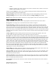
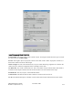
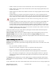


Table Of Contents
- Chapter 1. HPSS 7.1 Configuration Overview
- Chapter 2. Security and System Access
- Chapter 3. Using SSM
- 3.1. The SSM System Manager
- 3.2. Quick Startup of hpssgui
- 3.3. Configuration and Startup of hpssgui and hpssadm
- 3.4. Multiple SSM Sessions
- 3.5. SSM Window Conventions
- 3.6. Common Window Elements
- 3.7. Help Menu Overview
- 3.8. Monitor, Operations and Configure Menus Overview
- 3.9. SSM Specific Windows
- 3.10. SSM List Preferences
- Chapter 4. Global & Subsystem Configuration
- 4.1. Global Configuration Window
- 4.2. Storage Subsystems
- 4.2.1. Subsystems List Window
- 4.2.2. Creating a New Storage Subsystem
- 4.2.3. Storage Subsystem Configuration Window
- 4.2.3.1. Create Storage Subsystem Metadata
- 4.2.3.2. Create Storage Subsystem Configuration
- 4.2.3.3. Create Storage Subsystem Servers
- 4.2.3.4. Assign a Gatekeeper if Required
- 4.2.3.5. Assign Storage Resources to the Storage Subsystem
- 4.2.3.6. Create Storage Subsystem Fileset and Junction
- 4.2.3.7. Migration and Purge Policy Overrides
- 4.2.3.8. Storage Class Threshold Overrides
- 4.2.4. Modifying a Storage Subsystem
- 4.2.5. Deleting a Storage Subsystem
- Chapter 5. HPSS Servers
- 5.1. Server List
- 5.1. Server Configuration
- 5.1.1. Common Server Configuration
- 5.1.1. Core Server Specific Configuration
- 5.1.2. Gatekeeper Specific Configuration
- 5.1.3. Location Server Additional Configuration
- 5.1.4. Log Client Specific Configuration
- 5.1.1. Log Daemon Specific Configuration
- 5.1.2. Migration/Purge Server (MPS) Specific Configuration
- 5.1.3. Mover Specific Configuration
- 5.1.3.1. Mover Specific Configuration Window
- 5.1.3.1. Additional Mover Configuration
- 5.1.3.1.1. /etc/services, /etc/inetd.conf, and /etc/xinetd.d
- 5.1.3.1.2. The Mover Encryption Key Files
- 5.1.3.1.3. /var/hpss/etc Files Required for Remote Mover
- 5.1.3.1.1. System Configuration Parameters on IRIX, Solaris, and Linux
- 5.1.3.1.1. Setting Up Remote Movers with mkhpss
- 5.1.3.1.2. Mover Configuration to Support Local File Transfer
- 5.1.1. Physical Volume Repository (PVR) Specific Configuration
- 5.1.1. Deleting a Server Configuration
- 5.1. Monitoring Server Information
- 5.1.1. Basic Server Information
- 5.1.1. Specific Server Information
- 5.1.1.1. Core Server Information Window
- 5.1.1.1. Gatekeeper Information Window
- 5.1.1.1. Location Server Information Window
- 5.1.1.2. Migration/Purge Server Information Window
- 5.1.1.3. Mover Information Window
- 5.1.1.1. Physical Volume Library (PVL) Information Window
- 5.1.1.2. Physical Volume Repository (PVR) Information Windows
- 5.1. Real-Time Monitoring (RTM)
- 5.2. Starting HPSS
- 5.1. Stopping HPSS
- 5.2. Server Repair and Reinitialization
- 5.1. Forcing an SSM Connection
- Chapter 6. Storage Configuration
- 6.1. Storage Classes
- 6.2. Storage Hierarchies
- 6.3. Classes of Service
- 6.4. Migration Policies
- 6.5. Purge Policies
- 6.6. File Families
- Chapter 7. Device and Drive Management
- Chapter 8. Volume and Storage Management
- 8.1. Adding Storage Space
- 8.2. Removing Storage Space
- 8.3. Monitoring Storage Space
- 8.4. Dealing with a Space Shortage
- 8.5. Volume Management
- 8.6. Monitoring and Managing Volume Mounts
- 8.7. New Storage Technology Insertion
- Chapter 9. Logging and Status
- Chapter 10. Filesets and Junctions
- Chapter 11. Files, Directories and Objects by SOID
- Chapter 12. Tape Aggregation
- Chapter 13. User Accounts and Accounting
- Chapter 14. User Interfaces
- Chapter 15. Backup and Recovery
- Chapter 16. Management Tools
its data. When data is being written to a volume, it will be shown in Allocated state. When the End Of
Media marker is reached during a tape write operation, the volume will enter EOM state. If the number of
segments on the volume drops to zero after reaching EOM, the state will change to Empty. The volume
may be placed in Deny state by the server depending on the setting of the VV Condition.
Storage Class. The storage class to which the tape virtual volume is assigned.
Map Flags. Information about the state of the volume. Contains one of the following values:
•Never Written – Data has not been written to the volume.
•Retired – New data will not be written to this volume.
•Repack Output – All files on this volume were written there by the repack process.
Max Written Length. The total number of bytes that have been written to the volume. Each time the
volume is written, this number is incremented by the number of bytes written. This number is not
decremented when storage segments are deleted from the volume.
Active Length. The sum of the number of bytes in active storage segments. As segments are added to the
volume, this number increases. As segments are deleted, this number decreases.
Estimated Size. The estimated size of the volume in bytes. It is only an estimate of the number of bytes
that can be written on a tape volume. Depending on the compression characteristics of the data, the actual
number of bytes may be smaller or greater.
Space Left. The estimated number of bytes that may still be written to the tape virtual volume. It is
initially set to Estimated Size and is decremented as storage segments are written. It is not incremented
when storage segments are deleted.
Because of the variable compressibility of data written to tapes, this value may behave strangely. For
instance, the end of the media (EOM) may be reached earlier than estimated, causing this value to
become 0 quite suddenly. Conversely, EOM may be reached later than expected. In this case, Space Left
will be decremented until it reaches a value of 1, then remain at 1 until EOM is reached.
Number of Reads. The number of times the tape volume has been read.
Number of Writes. The number of times the tape volume has been written.
Time Last Read. The date and time the volume was last read. If this field is blank, the tape volume has
not been read.
Time Last Written. The date and time the volume was last written. If this field is blank, the tape volume
has not been written.
PVL Job ID. The PVL job ID in which this volume is mounted. This field will be zero if the volume is
not mounted.
Current Position. The address to which the tape is positioned, expressed as an HPSS Relative Stripe
Address. The Relative Address consists of two parts, the tape section and the byte offset. Tape sections
are the data written between a pair of tape marks. The byte offset is the offset from the beginning of the
current section to the place where the tape read or write is to take place. When reading the tape, this
address is set to the initial location where the tape read begins, then advances as the read progresses.
When writing a tape, this value is set to the Next Write Address, and then advances as the tape is
written. Updates to this field occur when I/O operations complete, so in some cases significant amounts
HPSS Management Guide November 2009
Release 7.3 (Revision 1.0) 276