
Computer Drive User Manual


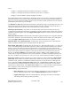

Table Of Contents
- Chapter 1. HPSS 7.1 Configuration Overview
- Chapter 2. Security and System Access
- Chapter 3. Using SSM
- 3.1. The SSM System Manager
- 3.2. Quick Startup of hpssgui
- 3.3. Configuration and Startup of hpssgui and hpssadm
- 3.4. Multiple SSM Sessions
- 3.5. SSM Window Conventions
- 3.6. Common Window Elements
- 3.7. Help Menu Overview
- 3.8. Monitor, Operations and Configure Menus Overview
- 3.9. SSM Specific Windows
- 3.10. SSM List Preferences
- Chapter 4. Global & Subsystem Configuration
- 4.1. Global Configuration Window
- 4.2. Storage Subsystems
- 4.2.1. Subsystems List Window
- 4.2.2. Creating a New Storage Subsystem
- 4.2.3. Storage Subsystem Configuration Window
- 4.2.3.1. Create Storage Subsystem Metadata
- 4.2.3.2. Create Storage Subsystem Configuration
- 4.2.3.3. Create Storage Subsystem Servers
- 4.2.3.4. Assign a Gatekeeper if Required
- 4.2.3.5. Assign Storage Resources to the Storage Subsystem
- 4.2.3.6. Create Storage Subsystem Fileset and Junction
- 4.2.3.7. Migration and Purge Policy Overrides
- 4.2.3.8. Storage Class Threshold Overrides
- 4.2.4. Modifying a Storage Subsystem
- 4.2.5. Deleting a Storage Subsystem
- Chapter 5. HPSS Servers
- 5.1. Server List
- 5.1. Server Configuration
- 5.1.1. Common Server Configuration
- 5.1.1. Core Server Specific Configuration
- 5.1.2. Gatekeeper Specific Configuration
- 5.1.3. Location Server Additional Configuration
- 5.1.4. Log Client Specific Configuration
- 5.1.1. Log Daemon Specific Configuration
- 5.1.2. Migration/Purge Server (MPS) Specific Configuration
- 5.1.3. Mover Specific Configuration
- 5.1.3.1. Mover Specific Configuration Window
- 5.1.3.1. Additional Mover Configuration
- 5.1.3.1.1. /etc/services, /etc/inetd.conf, and /etc/xinetd.d
- 5.1.3.1.2. The Mover Encryption Key Files
- 5.1.3.1.3. /var/hpss/etc Files Required for Remote Mover
- 5.1.3.1.1. System Configuration Parameters on IRIX, Solaris, and Linux
- 5.1.3.1.1. Setting Up Remote Movers with mkhpss
- 5.1.3.1.2. Mover Configuration to Support Local File Transfer
- 5.1.1. Physical Volume Repository (PVR) Specific Configuration
- 5.1.1. Deleting a Server Configuration
- 5.1. Monitoring Server Information
- 5.1.1. Basic Server Information
- 5.1.1. Specific Server Information
- 5.1.1.1. Core Server Information Window
- 5.1.1.1. Gatekeeper Information Window
- 5.1.1.1. Location Server Information Window
- 5.1.1.2. Migration/Purge Server Information Window
- 5.1.1.3. Mover Information Window
- 5.1.1.1. Physical Volume Library (PVL) Information Window
- 5.1.1.2. Physical Volume Repository (PVR) Information Windows
- 5.1. Real-Time Monitoring (RTM)
- 5.2. Starting HPSS
- 5.1. Stopping HPSS
- 5.2. Server Repair and Reinitialization
- 5.1. Forcing an SSM Connection
- Chapter 6. Storage Configuration
- 6.1. Storage Classes
- 6.2. Storage Hierarchies
- 6.3. Classes of Service
- 6.4. Migration Policies
- 6.5. Purge Policies
- 6.6. File Families
- Chapter 7. Device and Drive Management
- Chapter 8. Volume and Storage Management
- 8.1. Adding Storage Space
- 8.2. Removing Storage Space
- 8.3. Monitoring Storage Space
- 8.4. Dealing with a Space Shortage
- 8.5. Volume Management
- 8.6. Monitoring and Managing Volume Mounts
- 8.7. New Storage Technology Insertion
- Chapter 9. Logging and Status
- Chapter 10. Filesets and Junctions
- Chapter 11. Files, Directories and Objects by SOID
- Chapter 12. Tape Aggregation
- Chapter 13. User Accounts and Accounting
- Chapter 14. User Interfaces
- Chapter 15. Backup and Recovery
- Chapter 16. Management Tools
named /dev/lmcp0 and /dev/lmcp1 respectively. Control connections must be made prior to
configuration of the /dev/lmcpX devices or undefined errors may result. For Linux systems, the symbolic
library name defined in /etc/ibmatl.conf (e.g., 3494a) should be used.
For RS-232 and Ethernet connected robots, the device special files support both command and async
capabilities. If only one device special file is created, the environment variables or configuration should
be set so that both the command and async ports point to that one special file. It is also possible to create
two device special files and arbitrarily select one to be the command port and the other to be the async
port. The PVR can then be configured to recognize the ports as described above.
HPSS can share an IBM robot with other tape management systems. If a robot is shared, care must be
taken to make sure that a drive is not used by any other tape management system while that drive is
configured as unlocked in the HPSS PVL. This is important because HPSS periodically polls all of its
unlocked drives even if they are not currently mounted. The two LMCP device special files (or possibly
one file in the case of an RS-232 or Ethernet controlled robot) are not available to other tape management
programs. Additional device special files may be created for other programs. Other programs can send
commands to the robot at the same time as HPSS through the additional device special file.
If the robot is placed in pause mode by an operator, an alarm will appear on the HPSS operator window.
All subsequent robot operations will silently be suspended until the robot is put back in automatic mode.
5.1.1.2. AML PVR Specific Configuration
5.1.1.2.1. AML PVR Specific Configuration Window
Field Descriptions
Cartridge Capacity. The total number of cartridge slots in the library dedicated to this HPSS PVR.
This may or may not be the total cartridge capacity of the library; a site might use part of the library for
some other HPSS PVR or for some non-HPSS application. The PVR uses the Cartridge Capacity field
and the Cartridge Alarm Threshold field to determine when to send an alarm that the total cartridge
threshold has been exceeded.
Cartridge Alarm Threshold. The percentage of the Cartridge Capacity at which the PVR will send an
alarm.
Same Job on Controller, Other Job on Controller, & Distance To Drive. These values are used by the
PVR when selecting a drive for a tape mount operation. The three values are essentially weights that are
used to compute an overall score for each possible drive. After the score has been calculated, the drive
with the lowest score is selected for the mount. If two or more drives tie for the lowest score, one drive is
selected at random. The score is calculated as follows:
Score =
Weight 1 * Cartridges from this job mounted on this drive’s controller +
HPSS Management Guide November 2009
Release 7.3 (Revision 1.0) 113