BROOKFIELD R/S RHEOMETER Operating Instructions Manual No. M/02-212 Brookfield Engineering Labs., Inc.
Operating Manual for R/S Rheometer Version 1.10 E, valid for firmware version 4.02 All rights reserved, the translation included. Any part of this Operation Manual cannot be reproduced in any form (as printed matter, photocopies, microfilms or in any other form) or processed, copied or disseminated using electronic system without written consent of Brookfield Viscometers Ltd.
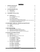
CONTENTS I. II. III. GENERAL DESCRIPTION 5 I.1 I.2 5 5 Use of the Rheometer Measuring Principle SYSTEM CONFIGURATION 6 II.1 II.2 II.3 6 8 8 R/S Rheometer Measuring Devices Computer System 9 INSTRUMENT INSTALLATION III.1 III.2 III.3 Stand Mounting Electrical Connections III.2.1 Temperature Sensor Pt100 III.2.2 AC-Adaptor III.2.3 Printer Connection III.2.4 Computer Connection Mounting of temperature controlled measuring devices III.3.
VI.7 VI.8 VII. Menu entries of the CONFIGURATION menu VI.7.1 Configuration → Set output mode VI.7.2 Configuration → MeasCount mode VI.7.3 Configuration → Reset meascount VI.7.4 Configuration → Set Time/Date VI.7.5 Configuration → Set RS232 Parameter VI.7.6 Configuration → Language VI.7.7 Configuration → Service, Service 2 Serial Data transfer via Interface RS232 MEASUREMENTS VII.1 VII.2 44 44 45 45 45 46 47 47 47 50 50 51 Measuring in manual mode Measuring in Remote-mode VIII. TECHNICAL DATA 52 IX.
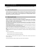
I. General Description In this chapter you get general information concerning use and measurement principle of your R/S Rheometer. I.1 Use of the Rheometer The R/S Rheometer system provides possibility of Newtonian fluids viscosity measurements, recording of flow curves as well as determination of viscosity functions of non-Newtonian fluids in steady shear flows.
II. System Configuration In this chapter you get information concerning system configuration, temperature control device, optional computer system and data- and signal flow of your Rheometer system.
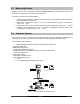
R/S Rheometer main instrument (minimum configuration) 14 BROOKFIELD 1 Main-Menue - Run Single - Run Program - Remote Power S T 4 O K 6 5 2 3 7 13 10 12 11 8 9 1 2 3 4 5 6 7 8 9 10 11 12 13 14 Brookfield Engineering Labs., Inc.
II.2 Measuring Devices Measuring devices are not included in the main delivery volume of R/S Rheometer and must be ordered in accordance with your measuring requirements. As measuring devices are optional supplied: • • • • II.3 coaxial standard measuring systems for R/S Rheometer (see Appendix A) with and without built-in temperature sensor Pt100 temperature control device “FTK-CC“ for use of cylinder measuring system in temperature range -10°C ...
III. Instrument Installation In this chapter you will know how to prepare your R/S Rheometer for the first measurements. You will know particularly, - how to mount the R/S Rheometer, details about the electric connections installation of accessories such as temperature control device, cooling device, measuring system hose connections. III.
III.2 Electrical Connections Connections for the electrical components of the R/S Rheometer are located at the instrument back side: Socket “Centronics“ parallel Printer interface Centronics RS232 Power DC Socket “RS232“ serial communication port Pt 100 Socket “Pt100“ for temperature sensor Socket “DC“ for ACadaptor connection Mains switch “POWER“ Any cables from and to R/S Rheometer can be connected or disconnected only when instrument is switched off! III.2.
III.2.2 AC-Adaptor The AC adaptor supplies R/S Rheometer with power. Only the AC-adaptor delivered by BROOKFIELD with your Rheometer may be used for power supply of R/S Rheometer. The AC-adaptor may be inserted to the socket with corresponding grounding only. Connect the AC adaptor only using the plug in a proper way grounded to avoid electric shocks or damage of the system components. Pay attention also to “Requirements to the mains cable” (see Appendix).
Please read information concerning installation of the computer system in this Operation Manual. III.3 Mounting of temperature controlled measuring devices In this chapter you get information concerning mounting and attachment of the following accessories components: • FTK-CC temperature control device for use of cylinder measuring system in the temperature range -10°C...
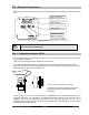
BROOKFIELD Main-Menue - Run Single - Run Program - Remote Power ST Cooling device KE OK Temperature control device FTK-CC Built in Pt100 Temperature control liquid from / to thermostatic device Connecting cable Pt100 Fig. 5.: Operation with FTK-CC and cooling device KE Thermostat connection to temperature control device FTK-CC Hoses’ connections are necessary to join a liquid circulation thermostat by operation of the R/S Rheometer with liquid circulation temperature control device “FTK-CC”.
-20 °C to +250 °C thermostat oil Thermostatic fluids can be ordered from BROOKFIELD. During measurements in the temperature range below -10°C and above +90°C the temperature control device “FTK-CC” may be put into operation only if the cooling liquid flows through the “KE” in order to prevent overheat of the measuring sensor. III.3.2 Mounting of the measuring device ME-CP/PP - Turn off the R/S Rheometer with the mains switch “POWER” at the instrument back side.
During measurements in the temperature range below -10°C and above +90°C the measuring device “ME-CP/PP” may be put into operation only if the cooling liquid flows through the “KE” in order to prevent overheat of the measuring sensor. Brookfield Engineering Labs., Inc.
Measuring device for cone/plate and plate/plate measuring systems ME CC/CP Brookfield Engineering Labs., Inc.
III.3.3 Mounting of the cooling device KE The optionally supplied cooling device “KE” must be used in case of the R/S Rheometer operation with the liquid temperature control device “FTK-CC” or measuring device “ME-CP/PP“ in the temperature range below -10°C and above +90°C. When using cooling device KE temperature range of temperature control device “FTK-CC“ and measuring device “ME-CP/PP“ is expanded to -20°C... +180°C.
IV. Environment, handling, cleaning and maintenance In this chapter you get information concerning environment, handling, cleaning and maintenance of your R/S Rheometer. IV.1 Operating environment, Storage Find comfortable, convenient working place where you install your R/S Rheometer. It must be enough room for installation of the stand, measuring system, measuring substances and peripheral devices (for example printer, computer and thermostat).
Check that any liquid does not penetrate into the housing (e.g. through the instrument connecting plugs) and into the bearings of the measuring drive. It results in the instrument damage! IV.4 Maintenance The R/S Rheometer is designed for long-term operation. Nevertheless we recommend a regular maintenance in one-year cycle by a service engineer of BROOKFIELD or of corresponding representation.
V. Measuring Systems In this chapter you get information concerning use of the measuring system. At present the following measuring system types are supplied: a) Standard measuring systems MS-CC48...CC8 DIN/RC and DG-DIN/RC for measurement without temperature control device FTK-CC consists of: - measuring cup for R/S Rheometer (MB-CC48...MB-CC8/RC and MB-DG/RC) depending on measuring-system - measuring cup bottom - measuring bob (MK-CC48...
Insert carefully the measuring bob into the measuring bob coupling. Pay attention to insert the measuring bob shaft into the measuring bob coupling without impact. Move down the coupling sleeve of the measuring bob coupling (ring covered). Fasten the measuring cup at the measuring cup mounting flange with the help of measuring cup thread. By moving down the stand, immerse the measuring cup into the substance up to the ring mark or up to the point where diameter of measuring cup increases. Fig. 7.
Temperature range max.: 0°C ... +90°C. The cooling device “KE” is required to expand the temperature range to -20°C ...+180°C The temperature sensor Pt100 may be immersed in medium only at 2/3 of the metal rod length! Cable must be always outside the medium. If you want to measure with temperature control, the thermostat must be pre-set at the desired temperature and you should wait till the necessary temperature of the substance is reached (e.g.
To remove the measuring system after the measurement first open the measuring bob coupling and then unscrew the measuring cup screw of temperature control device. Attention: If you have carried out measurements at higher or very low temperatures please take care: Some accessible surfaces can become very hot or cold. Before removing measuring system please wait till the system-surface-temperature equalized to nearly room temperature and allows you to touch the system without danger.
In order to avoid thread backlash, the height adjustment ring must be now obligatory turn through to “0.4” (turn to the right = lift) and then again return back to the 0/red position. Now screw on the inner hexagon screw at measuring bob shaft finger-tight ; this fixes the measuring bob in this position. After rotating the scale mark from 0-/red position to the 0/0 position the cone/plate measuring device is ready for measurements.
VI. Operation and Menue System In the following chapter you will get overview on operations, menue system of R/S Rheometer and measurements, both in manual and PC controlled modes. The menue-system of R/S Rheometer (firmware-version 4.02) is a dual-language system. Following languages are software selectable: • English • German Desired language can be selected via menue item Configuration→Language (if English language is active) or Konfiguration→Sprache (if German language is active).
VI.1 Keyboard BROOKFIELD - menue: previous menue-entry - input: increment value/letter MAIN-menue - Run Single - Run Program - Remote > START/STOP - back to parent menue - break - start of measurement - break of measurement R/S Rheometer - menue next menue entry - input: decrement value/letter ST OK - one digit to the left OK - enter - select - one digit to the right All user inputs are made with help of 6 keys located below LCD-Display. Some of the keys are of multiple use, i.e.
Key-function dependent to executed operation key operation Function of key example Menue goto previous menue-entry (above active one) increment „Utilities“ → „Remote“ Value-input Selection from List list entry above active entry (previous) Menue goto next menue-entry (below active one) decrement Value-input Selection from List list entry below active entry (next) Menue goto previous menue-entry (above active one) one digit to the right Value-input Selection from List list entry above active
VI.
Menu handling Because LCD display of R/S Rheometer cannot show simultaneously all menue items, only part of the menue (three entries) is always displayed. Two arrows “>“ at the right side of display inform you, if there are still entries in the menue, either above (the arrow in the 2nd line), or below (the arrow in the 4th line). Currently active (but still not selected) entry is marked by blinking black field (cursor) at the left part of LCD.
• • • Selection of a program or a measuring system you want to edit in “Edit Program” and “Meas. systems”; Answering a request “YES” ↔ “NO”. Selection of a program to start in “Run Program” Keys and move cursor (= pre-selected entry) in the list upwards and downwards. Key OK selects the pre-set entry from the list and ST key interrupts selection from the list (only if possible).
Using now and keys you can move cursor leftwards (rightwards). To process the next digit we push key and get: Input Values: Val.[1/s]: 0200.00 Nr. of MP: 010 Time[s]: 0100 Now we can process the next digit. In order to insert here “9” it’s advisable to decrement once current “0”, rather than to increment it nine times. So, we push key and get: Input Values: Val.[1/s]: 0290.00 Nr.
VI.5 Menue entries (MAIN menue) Menue entries (see Menue System in Chapter 6.2) may either contain submenues (e.g. “Utilities” or “Configuration”) or directly executing of one of the Rheometer’s functions. At Tree Chart in Chapter 6.2 all gray fields without further right branches serve to call functions. Those ones with right branches are submenues. Let us remind keyboard layout from Chapter 6.2.
Output of MPs to: -No output device -Memory <^> Menu Start At this point you either can start a measurement by pressing ST key, or return back to Main menue using key. In this example, we see that the measurement data will be saved in Memory only. No other output device is defined. Output devices are printer or serial interface RS232 of the Rheometer. Selection of these devices is described in Chapter ”Configuration -> Set output mode”.
After measurement, or after a break, the display field for Step indicates “END” or “BREAK”. The Display toggles in intervals of about 4 seconds between last displayed measure point and a measuring end information like this: angezeigt: Break reason or end Type / name of executed progr. Duration until break or end Program end Single mode Total time:100s Total #MP:10 Number of measure points measured By pressing OK key you return to the MAIN-Menue.
If you have passed these points, before starting a measurement, the Rheometer will indicate, where the measure points will be written to. Output of MPs to: -Printer -Memory <^> Menue Start At this point you either can start a measurement by pressing ST key, or return back to Main menue using key. In this example we see, that measurement points will be saved in the memory and will be printed at the printer, so be sure that printer is connected to the Rheometer and ready for operation (=output device).
After measurement, or after a break, the display field for Step indicates “END” or “BREAK”. The Display toggles in intervals of about 4 seconds between last displayed measure point and a measuring end information like this: Break reason or end Type / name of executed progr. Duration until break or end Program end Test Total time:200s Total #MP:40 Number of measuring points measured By pressing OK key you return to the MAIN-Menue. VI.5.
VI.6 Menue entries in the Utilities-Menue Utilities menue, as its title presumes, contains several useful functions corresponding to measurements.
• • • • • measuring system to be used in the measurement Number of steps start and end value of each step Number of measurement points for each step Duration of each step preset value as a function of time: D[1/s] 100 80 D[1/s]=f(t) 60 40 20 0 0 60 t[s] 120 180 As an example, we would like to consider a standard measurement. 1. Step: shear rate increases within 60 sec from 10.00 to 100.00 s-1 . 2. Step: shear rate remains at the level of 100.00 s-1 for 60 sec. 3.
Available programs contain a name Select PROG to edit 1) Prog xyz 2) Test 3) NEW > All free (non-defined) programs are marked as NEW All free memory parts are marked as NEW. In order to avoid overwriting of already available programs, please, select a NEW program to be edited. After selection of the program with OK key you will be requested to select a measuring system.
For every step, there are the following inputs: Start Value Input Step Nr 1 Start[1/s]: 0010.00 End[1/s]: 0100.00 Nr of MP: 010 End Value Number of MP (measur. points) (input of numbers: see Chapter 6.4) Minimum- and maximum-values of start values and end values depend on selected measuring system for shear rate (D[s-1]) and shear stress (Tau[Pa]).
Saving of the Program: (2) TEST Press to save If you push OK key now, the Program will be saved. If you push any other key, the entries are abandoned and previous parameters remain (the current ones, before the edit). VI.6.3 Utilities → Print Programs This function prints the parameters of defined programs in memory at the printer. Be sure that printer is connected to the Rheometer and ready for operation.
After selection of the measuring system, you will be requested to input sequentially: its name, tau_prom and k_gamma. Enter Meas. Sys. #4 Name: CP25 tau_prom: 01.1418 k_gamma: 01.2910 The measuring system name is a alpha-numerical entry, factors tau_ prom and k_gamma are input as numerical entries (see Chapter 6.4). When done, a security request follows, if you really want to save new parameters. PRESS to save Name: CC25 tau_prom: 01.1418 k_gamma: 01.
If you have chosen the output device, you have to select the measuring series to transfer. All available data is displayed in a list. Meas. series counter MEASCOUNT Select Program: - 1;17.10;11:20 - 2;17.10;12:30 - 3;17.10;13:40 Date of measurement Time of measurement After selection of a measurement series, the data of the series will be printed as Table or transferred via the serial interface. After completion of data transfer the Rheometer returns to Utilities Menue. VI.6.
VI.7 Menu entries of the CONFIGURATION menu The Entries: • Set output-mode sets output-mode of measuring data at the time of measurement into the printer or into the serial interface. • Set meascount-mode sets the counter mode (if the MEASCOUNT counter of measuring series will be daily cleared or not). • Reset meascount reduces the MEASCOUNT counter of measuring series by 1. • Set time/date Input of date and time • Set RS232 Param.
b) for output to the serial interface (RS232), the receiving device (normally a PC) is set to the data transfer parameters of the Rheometer (see chapter 6.7.5 “RS232 Parameters”) and ready to receive data. If the receiving side is not ready, the data will not be transmitted or will be transmitted to Null. (See also chapter 6.8 “Serial data transfer”). VI.7.2 Configuration → MeasCount mode Measurement series counter MEASCOUNT is a counter, increasing its count by 1 when starting a measurement.
After setting time and date you will be requested if you want to set clock for new time. New Time/Date 17:15 17.03.01 Press to save Using OK saving. key, you can set new time, or using ST key you can return back to the menue without Note: New time is input into the clock only after pressing running with seconds=00. OK key. When pressing the key, time starts VI.7.5 Configuration → Set RS232 Parameter This function allows changing communication parameters of the serial interface.
• Stopbits [Bit]: 1 or 2 Choose the requested parameter from the list of available values and select it by pressing OK key. Example Baudrate: Baudrate: -4800 _9600 -19200 After selecting all parameters, new setting of communication parameters is displayed: RS232: 19200,8,n,1 =storing with OK key you transfer this parameters to nonvolatile memory of R/S Rheometer. These changed transfer settings will be saved into memory and will remain in the memory also after switching off the instrument. VI.7.
3. The receiver is ready for reception and can (due to sufficient PC and memory capacity) receive or save received data at selected baudrate. It is worth to demonstrate reception with the help of Terminal program under Microsoft Windows. 1. Switch off the Rheometer and PC. 2. Connect the Rheometer (connector RS232 at the instrument back side) and one of free serial interface (e.g. COM2) of the PC. Here use only the data link (supplied by BROOKFIELD as an accessory). 3. Switch on the PC and the Rheometer.
14. Start measurement at the Rheometer. Measurement points must now be seen as text at the PC display after a short period of time. 15. After completed data transfer of one or several measurements into the selected text file, break the data transfer and end the Terminal Program. If it is necessary to select some other receiver for serial data transfer (not a PC), pin layout of this receiver must be checked before the connection.
VII. Measurements VII.1 Measuring in manual mode To carry out measurements in manual mode you can act in correspondence with the following brief instructions: Measurement control: • • • • Fasten the R/S Rheometer at stand (see Chapter 3). Connect the AC adaptor (see Chapter 3). Connect, if necessary, the printer (see Chapter 3). Fill and mount the standard measuring system (see Chapter 5).
Point to the fact that any substance or solvent do not ingress into measuring bob coupling, measuring drive or electronics. • • • • • Check the presence of the temperature control liquid. Wait for temperature control till the attainment of the desired temperature in the measuring substance. Start a program or a single measurement (see Chapter 6). After ending of the measurement and switching off of the temperature control wait till the cooling/warming of the medium to room temperature.
VIII. Technical data R/S Rheometer Dimensions 480 mm x 300 mm x 290 mm Weight 8 kg Nominal operating voltage Power consumption (average) Power consumption (maximum) +/- 15 V, 5 V 12 W 22 W Ambience conditions Temperature in operation out of operation Relative humidity (not condensable) in operation out of operation Accuracy 10° to 40°C 10° to 45°C 20% to 80% 10% to 90% ± 1.0 % of maximum range value ± 1 digit Torque range Mains operation 0.05 to 50 mNm Torque resolution 0.01 mNm Speed range 0.
FTK-CC Dimensions (Width x Height x Depth) 94 mm x 55 mm x 170 mm Weight 600 g Temperature range standard range with cooling device -10°C to +90°C -20°C to +180°C Measured or evaluated values The preset values and measured values are listed below as well as all evaluated values: Value Symbol Physical Unit Speed n [min-1] M [1] Temperature T [°C] Time t [s] Shear rate γ⋅ [s-1] Shear stress τ [Pa] Dynamic viscosity η [Pas] Torque (relative) (1000 ‰ ^= 50 mNm) Brookfield Engineeri
IX. Guarantee Brookfield Engineering Laboratories guarantees the faultless functioning of this instrument insofar as it is Brookfield Viscometers Ltd guarantees the faultless functioning of this instrument as far as it is used, maintained, connected and handled in accordance with this Operation Manual. The guarantee period is 1 year from the date of delivery. Place of the guarantee fulfillment is Brookfield Viscometers Ltd, Harlow, U.K.
APPENDIX A1Data sheets of standard measuring systems Table Standard cylinder measuring systems according to DIN 53019 / ISO 3219 (consists of measuring bob and measuring cup) For R/S Rheometer three types of measuring bobs are available: − MB-CC48 ... CC8 DIN/RC − MB-CC48 ... CC8 DIN/FTK − MBA-CC48...CC8 DIN/FTK with EMB-CC48...CC8 Measuring system CC48 CC45 CC25 CC14 CC8 Shear rate range [s-1] 0 ... 4,114 0 ... 1,032 0 ... 1,032 0 ... 1,032 0 ... 1,032 Shear stress range [Pa] 0 ... 206 0 ...
Table Double Gap cylinder measuring system according to DIN 53453 (consists of measuring bob and measuring cup) Measuring system Shear rate DG DIN range[s-1] 0 ... 4,031 Shear stress range [Pa] 0 ... 67 Viscosity range [Pas] 0.001 ... 1.30 Filling volume [ml] 22.5 Shear rate factor Kγ⋅ [min/s] 5.039 Shear stress factor τ‰ [Pa] 0.067 Inner radius of measuring bob R2 [mm] 22.75 Outer radius of measuring bob R3 [mm] 23.5 Inner radius of measuring cup R1 [mm] 22.
Table Cone/Plate measuring systems (DIN 53018) (consists of measuring cone and measuring device ME-CP/PP) Measuring system C25-1 C25-2 C50-1 C50-2 C75-1 C75-2 Shear rate range [s-1] 0 ... 4,800 0 ... 2,400 0 ... 4,800 0 ... 2,400 0 ... 4,800 0 ... 2,400 Shear stress range [Pa] 0 ... 12,223 0 ... 12,223 0 ... 1,528 0 ... 1,528 0 ... 452 0 ... 452 Viscosity range [Pas] 0.25 ... 1,629 0.5 ... 3,259 0.03 ... 203 0.06 ... 407 0.009 ... 60 0.02 ... 120 Filling volume [ml] 0.08 0.3 0.7 1.
A2 Error messages The R/S Rheometer is rather error resistive, when errors occur they are determined and the user is informed on the LCD display. The most frequent error massages are explained in this Chapter. Range Error Cause: User’s error at input. The user has tried to input a value that is less than the allowed minimum value or is more than the allowed maximum value. Message: Example of error input of a preset value Name of value which is out of range Range error End value: min : 0.90 max : 1032.
Zero Calibration Error Cause: An impermissible high value was measured during carrying out of zero point calibration of the Rheometer Message: Error #3 Zero cal. error! Please retry cal. cont. stop What to do: Push ST key. Check if the measuring system has been really removed from the Rheometer. Retry zero point calibration.
BREAK: SPEED MAX Cause: Maximum speed exceeded during carrying out a measurement. a) You have selected too high shear stress or too high torque value for the measuring substance. b) You have started torque- or shear stress measurement without substance in measuring system. Message: BREAK: Speed max! Single mode total MP: 10 total time: 60 What to do: Push OK key. Select smaller shear stress or torque values for this measurement. Brookfield Engineering Labs., Inc.
A3 Pin-layout of the serial data cable The Rheometer is provided with a serial interface with 25 pin Sub-D-connector (male) at the back side of the instrument. The serial interface is marked as RS232. The signal level in accordance with RS232 is in the range between +12 V and -12 V.
A4 Requirements to the mains connecting cables The AC-adaptor unit of the R/S Rheometer enables operation of the Rheometer with supply voltage in the range of 100 to 240 V AC with frequencies from 50 to 60 Hz. The mains connecting cable that you have received with your R/S Rheometer in some cases may not meet with the requirements of the country in which you are using this Rheometer. You must obligatory use a mains connecting cable that meets the specific requirements of the relevant country.
The mains plug must be 2-pin shockproof plug according to the Japanese Industrial Standard C8303 (15A,125V). - A5 Language cross reference English German English German !M low! !M ->0! BREAK ABBR. Break:speed max! Abbruch Drehz. max! Break:torque max! Abbruch Mom. max.! Change RS232 Param.?Aendern RS232-Par.? Clear memory? Speicher loeschen? continue weiter Edit Meas.-Sys. Eing. Mess-Sys. Edit programm first! Zuerst Eingabe Prog! Edit PROGRAM-NameEing.
German menue system of RC20 HAUPTMenue Einzelmessung ProgrammMessung Remote Hilfsmittel Measurement with constant shear rate or shear stress Measurement with pre-defined programm Measurement under PC-control (remote control) Nullpkt.Abgleich Zero-point calibration Programme bearb.
Index ME-CP/PP, 23 ME-CP/PP measuring device, 6, 8, 12, 14, 17 memory, 33, 35 memory, clear, 43 memory, internal, 44 memory, print data, 42 Menü-System, 25 C cleaning, 18 computer system, 6, 8, 11 cooling device, 12 O D output mode, 44 Date, setting, 45 P E power supply, 11 printer, 44 Printer, 11 Program, edit, 37 Program, print, 41 PT 100, 10 Pt 100-clamp fixture, 10 Pt100, 8 electrical connections, 10 Error messages, 58 F FTK-CC, 6, 8, 12, 22 G Q General description, 5 guarantee, 54 quick fi