Infoprint 1145 Setup Guide S510-1965-00 Argecy Computer Corporation 248-324-1800
Argecy Computer Corporation 248-324-1800
Infoprint 1145 Setup Guide S510-1965-00 Argecy Computer Corporation 248-324-1800
Edition: July 2001 Lexmark and Lexmark with diamond design, MarkNet, and MarkVision are trademarks of Lexmark International, Inc., registered in the United States and/ or other countries. ImageQuick is a trademark of Lexmark International, Inc. PostScript® is a registered trademark of Adobe Systems Incorporated. PostScript 3 is Adobe Systems’ designation of a set of printer commands (language) and functions included in its software products.
Table of contents Preface . . . . . . . . . . . . . . . . . . . . . . . . . . . . . . . . . . . . . . . . . . vii About your printer . . . . . . . . . . . . . . . . . . . . . . . . . . . . . . . . . . vii About this book . . . . . . . . . . . . . . . . . . . . . . . . . . . . . . . . . . . . ix Other sources of information . . . . . . . . . . . . . . . . . . . . . . . . . . x Step 1: Select a location for your printer . . . . . . . . . . . . . . 1 Allowing enough space . . . . . . . . . . . . . . . . . . .
Step 6: Install memory and option cards . . . . . . . . . . . . . 23 Accessing the printer system board . . . . . . . . . . . . . . . . . . . .24 Installing memory cards . . . . . . . . . . . . . . . . . . . . . . . . . . . . .25 Installing an optional firmware card . . . . . . . . . . . . . . . . . . . .28 Installing option cards . . . . . . . . . . . . . . . . . . . . . . . . . . . . . . .30 Reinstalling the system board . . . . . . . . . . . . . . . . . . . . . . . . .
Step 11: Install the optional envelope feeder . . . . . . . . . . . 71 Step 12: Load print media . . . . . . . . . . . . . . . . . . . . . . . . . . 73 Loading trays 1, 2, and 3 . . . . . . . . . . . . . . . . . . . . . . . . . . . .74 Loading trays 4 and 5 . . . . . . . . . . . . . . . . . . . . . . . . . . . . . . .80 Loading the multipurpose feeder . . . . . . . . . . . . . . . . . . . . . .83 Loading the optional envelope feeder . . . . . . . . . . . . . . . . . . .86 Step 13: Attach cables . . . . . .
Index . . . . . . . . . . . . . . . . . . . . . . . . . . . . . . . . . . . . . . . . . . 107 Using the publications CD . . . . . . . . . . . . . . . . . . . . . . . . .
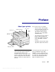
Preface About your printer Three printer models are available: • The base model, delivering 600 dots per inch (dpi) resolution at up to 45 pages per minute (ppm), ships with two 500-sheet trays. This model comes with 32MB of standard memory. • The network model comes with an Ethernet 10BaseT/100BaseTx print server installed. This model comes with 64MB of standard memory. • The duplex network model, which ships with a duplex unit attached.
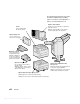
The following figure illustrates the printer and all the available paper handling options. Instructions for installing these options are included in this book. Optional 10-bin mailbox Printer Comes standard with two 500-sheet trays. Provides up to ten output bins for organizing printed documents. Either the optional mailbox or the optional finisher may be attached to the printer. Optional duplex unit Lets you print on both sides of a sheet of paper.
About this book Note: See the safety information on the inside front cover before setting up your printer. Conventions This Setup Guide contains all the information you need to set up your new printer. This manual provides detailed instructions for unpacking and setting up the printer, installing supplies and options, loading media, launching the drivers CD to install printer drivers and utilities, and printing information from the publications CD.
Other sources of information Publications CD Note: The publications CD is located in the back of this book. Drivers CD The publications CD provides information about loading paper, clearing error messages, ordering and replacing supplies, installing maintenance kits, and troubleshooting. It also provides general information for administrators. The drivers CD contains all the necessary printer drivers to get your printer up and running.
Clearing Jams card The Clearing Jams card provides easy access to information about clearing print media jams in the printer and its options. Store the Clearing Jams card in the convenient printer pocket that attaches to your printer.
xii Preface Argecy Computer Corporation 248-324-1800
Step 1: Select a location for your printer CAUTION! The printer weighs 46.8 kg (103 lbs) and requires at least two people to lift it safely. Choosing the correct location for your laser printer is vital to ensuring that the printer provides you with the quality of service you expect.
For a base printer When selecting a location for your printer, make sure you have at least the amount of space indicated in the figure. 200 mm (8 in.) 364 mm (14 in.) 200 mm (8 in.) 10 ( 42 60 i n. m m ) 700 mm (28 in.) mm 1084 .) in (43 460 mm (18 in.) With a duplex unit and a high capacity feeder or base cabinet When selecting a location for a printer with a high capacity feeder and duplex unit, make sure you have at least the amount of space indicated in the figure.
With finisher or mailbox 364 mm (14 in.) 63 (25 0 m in. m ) 20 (8 0 m i n. m ) 10 (4 2 6 0 m 46 in. m (18 0 m ) in. m ) When selecting a location for a printer with a finisher or mailbox, make sure you have at least the amount of space indicated in the figure. 1520 mm (60 in.) mm 2069 .) in 1 (8 1700 mm (67 in.) 20 (8 0 m in. m ) 10 (42 60 m in. m ) mm 364 in.) 4 (1 46 (18 0 m in. m ) 200 mm (8 in.) mm 1084in.
Considering environmental issues Moving the printer When choosing a place to set up the printer, make sure the location you select is: • A firm, level surface where the printer won’t be subjected to strong vibration • Well ventilated • Away from the direct airflow of air conditioners, heaters, or ventilators • Free of temperature or humidity extremes or fluctuations • Clean, dry, and free of dust • Away from direct sunlight At some point in the future you may decide to move the printer to a n
Step 2: Unpack the printer Now that you have chosen a location for your printer, you are ready to unpack it and prepare to set it up. Make sure you have the following items: • Printer with two 500-sheet drawers • Multipurpose feeder • Power cord • Print cartridge • Setup Guide with a publications CD The publications CD is located in the back of this book.
Step 3: Install the multipurpose feeder Note: If you will be attaching the optional envelope feeder during setup, skip this step and continue with either Step 4: “Set up the optional high capacity feeder” on page 9 or Step 5: “Set up printer supplies” on page 17. Your printer comes with a multipurpose feeder that can be used to load paper, transparencies, labels, or card stock. The multipurpose feeder holds approximately 35 sheets of paper.
2 Tilt the feeder end going into the printer first down slightly, as you align the posts on the feeder with the holes above the opening in the printer. Make sure the top of the feeder fits over the top of the edge coming out of the printer. (See the illustration on page 8.
3 Gently insert the feeder at this angle into the opening and then drop it down into place. The feeder should be firmly in place.
Step 4: Set up the optional high capacity feeder CAUTION! If you are installing a high capacity feeder sometime after setting up the printer, turn the printer off and unplug the power cord and any other cables before continuing. Your printer supports either an optional high capacity feeder or an optional base cabinet. The high capacity feeder contains one 500-sheet tray and two 1000-sheet trays for a total capacity of 2500 sheets of print media.
To set up the high capacity feeder or base cabinet: Warning! Lift the high capacity feeder 1 from the bottom. High capacity feeder Remove the high capacity feeder or cabinet from its packing materials. Locking clips, thumbscrews, and tray labels Warning! Be sure you remove the Be sure to remove the foam packing and tape from the trays. Save the carton and packing materials in case you need to repack the option.
Attaching a high capacity feeder or base cabinet The steps in this section explain how to connect your printer to a high capacity feeder. When the steps for a base cabinet are different, a note to the left of the step provides the necessary information. CAUTION! The printer weighs 46.8 kg (103 lbs) and requires at least two people to lift it safely. 1 Make sure the high capacity feeder cable is situated in the notch on the back of the feeder. 2 Have someone help you lift the printer.
Warning! Do not slide the printer across the high capacity feeder to position it. 3 Carefully place the printer on top of the high capacity feeder. Make sure the trays on the printer are lined up on the same side as the trays on the high capacity feeder. Be sure to align all four corners on the bottom of the printer with the corners on the top of the high capacity feeder. Small metal pins on the top of the high capacity feeder fit into grooves on the bottom of the printer.
Attaching the locking clips The locking clips keep the printer and the high capacity feeder properly aligned, helping to prevent them from being separated accidently. 1 Remove tray 2. a Pull the tray out fully. b Tilt the front of the tray upward. c Gently pull the tray out.
Note: If you are installing a base cabinet, open the cabinet door. 14 Set up the optional high capacity feeder Argecy Computer Corporation 248-324-1800 2 Open tray 3. 3 Attach the locking clips to the left and right sides of the trays. 4 Secure the locking clips using the thumbscrews.
Note: If you are installing a base cabinet, close the cabinet door. 5 Close tray 3. 6 Reinsert tray 2.
7 16 Set up the optional high capacity feeder Argecy Computer Corporation 248-324-1800 At the back of the printer, plug the high capacity feeder cable into the connector labeled “Tray” on the printer.
Step 5: Set up printer supplies You have unpacked your printer and chosen a location for it. Now you are ready to set up supplies. Installing the print cartridge Each print cartridge supports approximately 30,000 pages of singlesided printing, depending on the types of jobs you print and the amount of toner required for each page. The printer displays a message when it is time to replace the cartridge. You may want to keep a supply of print cartridges handy. Refer to the publications CD for details.
Note: If toner spills on the floor, do not clean it up using a vacuum or a wet cloth. Wipe up the spill with a dry cloth. If toner gets on clothing, be sure to wash the clothing in cold water. 18 Set up printer supplies Argecy Computer Corporation 248-324-1800 4 Remove the tape (on the top of the cartridge) and then gently pull the protective paper straight up and out of the cartridge. 5 Shake the cartridge vigorously in all directions to distribute the toner.
6 Holding the print cartridge by the handle and one end, align the cartridge with the slots inside the printer. 7 Slide the cartridge into the printer as far as it will go until it snaps into place.
8 Carefully pull the yellow tape completely out of the cartridge. Discard the tape. 9 Close the front door (Door F). Door F Preparing the fuser Note: You need a coin or a flat blade screwdriver for the following steps. 20 Set up printer supplies Argecy Computer Corporation 248-324-1800 The fuser supports approximately 300,000 pages of single-sided printing. The printer displays a message when it is time to replace the fuser. Refer to the publications CD for details.
1 Remove the two labels covering the screws on each side of the fuser. 2 Turn each screw one third turn counterclockwise. 3 Pull both screws straight out and then discard them. 4 Close the side door (Door A).
Applying the operator panel overlay (non-English only) If English is not your preferred language, attach the overlay with the translated button names to the printer operator panel. 1 Locate the overlay packaged with your printer. 2 Peel the protective backing off the overlay. 3 Align the holes in the overlay with the buttons on the operator panel, and then press it into place. 4 Peel the protective covering away from the overlay.
Step 6: Install memory and option cards You can customize your printer memory capacity and connectivity by adding optional cards.
Accessing the printer system board CAUTION! If you are installing memory 1 Locate the metal plate on the back of the printer. 2 Loosen the two thumbscrews. or option cards sometime after setting up the printer, turn the printer off and unplug the power cord and any other cables before continuing. The thumbscrews do not come completely off the plate. 3 Gently pull the thumbscrews until you can grasp the system board. 4 Pull the system board out just far enough to access the connector slots.
Installing memory cards Follow the instructions in this section to install either a printer memory card or a flash memory card. The system board has three connectors for optional memory cards. You can install any combination of printer memory and flash memory cards in the three connectors. However, the printer only recognizes one flash memory card at a time. 1 Access the system board. (See page 24 for instructions.) 2 Locate the memory connectors on the system board.
Warning! Printer memory and flash 4 memory cards are easily damaged by static electricity. Touch something metal on the printer before you touch a memory card. Unpack the memory card. Avoid touching the connection points along the edge of the card. Save the packaging. Connection points 5 26 Install memory and option cards Argecy Computer Corporation 248-324-1800 Align the notches on the bottom of the card with the notches on the connector.
Warning! Support the bottom of the system board when installing a card. 6 Notch While holding the system board from the bottom, push the memory card firmly into the connector until the latches on either end of the connector snap into place. It may require some force to fully seat the card. Notch Make sure each latch fits over the notch on the end of the card. 7 Repeat steps 4 through 6 to install other memory cards.
Installing an optional firmware card Warning! Optional firmware cards are Follow the instructions in this section to install an optional firmware card. The system board has one location where firmware cards can be installed. 1 Access the system board. (See page 24 for instructions.) 2 Unpack the firmware card. easily damaged by static electricity. Touch something metal on the printer before you touch a card.
3 System board holes Holding the firmware card by its sides, align the two pins on the card with the holes on the system board. Orient the card as shown. 4 While holding the system board from the bottom, push down until the firmware card is firmly in place. The entire length of the plastic connector on the firmware card must touch the system board. Some force may be required to fully install the card, but be careful not to damage the card’s connectors. Warning! Support the bottom of the system board.
Installing option cards Your printer has two connectors that support the following option cards: Note: The network and duplex network • Hard disk with adapter card printer models ship with an Ethernet print server already installed. • MarkNet internal print server • USB/Parallel 1284-C Interface Card • Parallel 1284-C Interface Card • Coax/Twinax Adapter for SCS • Tri-Port Adapter You need a small Phillips screwdriver to install these options.
Complete the following steps to install any of the option cards mentioned on page 30: 1 Access the system board (see page 24 for instructions) and locate the option card connectors. 2 Remove the metal plate covering the connector slot. Option card connectors Note: If you are installing two option cards, install the first one in the lower option card connector, so it will be easier to install the second card. Warning! Install hard disks in the top connector slot only. This prevents overheating.
Warning! Option cards are easily 3 damaged by static electricity. Touch something metal on the printer before you touch an option card. Unpack the option card. Save the packing materials. 4 Align the connector on the option card with the connector on the system board. The cable connectors on the side of the option card must fit through the connector slot. 32 Install memory and option cards Argecy Computer Corporation 248-324-1800 5 Push the option card firmly into the option card connector.
Reinstalling the system board 1 Gently push the system board back into the printer. 2 3 Tighten the two thumbscrews. Reconnect any previously connected cables on the back of the printer.
Step 7: Install the optional duplex unit CAUTION! If you are installing the duplex unit sometime after initial printer setup, turn the printer off and unplug the power cord before continuing. Note: If you are installing the duplex unit after having previously installed the optional envelope feeder, the envelope feeder must be removed before installing the duplex unit. Refer to the publications CD for help.
3 Hold the duplex unit as shown. 4 Attach the duplex unit to the top of the multipurpose feeder. a Holding the duplex unit parallel with the ground, attach the two stationary metal brackets on the duplex unit to the metal rods on the top of the multipurpose feeder. b Tilt the duplex unit toward the printer until the extendable metal bracket on the right snaps into place. 5 Pull out the cable on the left side of the duplex unit and fully extend it.
Note: When the duplex unit is in operation, the printer partially ejects paper, then draws it back into the duplex unit before it is fully ejected. Do not remove paper before it is completely ejected or a paper jam may result. 36 Install the optional duplex unit Argecy Computer Corporation 248-324-1800 7 Close the duplex unit by pushing it toward the printer until it latches into place. 8 Plug the duplex unit cable into the connector labeled “Duplex” on the back of the printer.
Step 8: Secure the wheels and leveling feet Note: This only applies if you have a high capacity feeder or a base cabinet attached to the printer. Once you have all the printer components attached and the printer is positioned where you want it, you need to stabilize it. 1 Lock the wheels by pushing down on the lever attached to them. 2 Rotate all the leveling feet until they touch the ground.
What do I do next? 38 Task Go to page… Set up the optional mailbox 39 Set up the optional finisher 53 Install the optional envelope feeder 71 Load print media 73 Secure the wheels and leveling feet Argecy Computer Corporation 248-324-1800
Step 9: Set up the optional mailbox Note: The printer can support either a mailbox or a finisher, but not both at the same time. Your printer supports an optional10-bin mailbox that helps you organize your printed documents. Before you can attach a mailbox, you must install either a high capacity feeder or a base cabinet. For help setting up a high capacity feeder or a base cabinet, see page 9. Note: The illustrations in this section show the printer with a high capacity feeder attached.
Removing the stacking arm Stacking arm CAUTION! If you are installing the mailbox sometime after initial printer setup, turn the printer off and unplug the power cord before continuing. 40 Set up the optional mailbox Argecy Computer Corporation 248-324-1800 Before you can attach a mailbox, you must remove the stacking arm from the printer. To remove the stacking arm, push the tab on the top of the arm toward the printer output bin until it snaps loose.
Unpacking the mailbox CAUTION! The mailbox weighs 15.9 kg (35 lbs) and requires two people to lift it safely. Warning! The mailbox must be set down with the door (Door F) facing the ground. Otherwise, the mailbox may be damaged. 1 Remove the mailbox and all other items from their packaging. Be sure to set the mailbox down with Door F toward the ground. Remove any plastic wrapping, shipping tape, and protective foam. Save the carton and packing materials in case you need to repack the mailbox.
2 Mailbox Upper portion of mailbox stand Paper stop — Mailbox with 10 output bins and handling tool — Mailbox stand: -- Upper portion stand piece -- 2 side stand pieces -- Side stand bracket — Stabilizing foot with L-pin — 3 thumbscrews — Paper stop If any items are missing or damaged, contact your point of purchase.
Attaching the mailbox stand 1 Position the side stand pieces so that the small metal knobs are toward the sides of the printer, as shown. 2 Insert the knobs into the slots in the printer. 3 Slide the side stand pieces down until they rest firmly in place.
4 Position the side stand bracket, connecting the printer and the stabilizer bar. a Position the bracket on the underside of the printer, on the same side as the side stand with the stabilizer bar.
b Slide the bracket so that the top fits over the stabilizer bar. Align the hole in the bracket with the hole in the stabilizer bar. c Insert the small thumbscrew through the bracket and stabilizer bar, and then tighten.
5 Insert a thumbscrew through the hole in the middle of each side stand piece, and then tighten the screws. 6 Slide the stabilizing foot over the high capacity feeder back foot. If the high capacity feeder back foot is completely lowered, especially on a carpeted surface, you may need to raise it off the ground before the stabilizing foot will properly fit over it.
7 Insert the L-pin through the holes in the stabilizing foot and back foot. 8 Rotate the end of the L-pin down into the slot in the stabilizing foot.
Warning! Make sure the upper portion is oriented correctly, with the taller side on the same end of the printer as the multipurpose feeder. 48 Set up the optional mailbox Argecy Computer Corporation 248-324-1800 9 Slide the upper portion of the stand down into the side stands until it snaps into place.
Positioning the mailbox CAUTION! The mailbox requires two 1 Be sure you have removed the stacking arm from the printer. (See “Removing the stacking arm” on page 40). 2 Have someone help you lift the mailbox, using the horizontal bar and the handling tool on the opposite side. 3 Align the mailbox post with the stand rail. 4 Carefully lower the mailbox onto the stand. people to lift it safely. Note: Be sure the mailbox cord is between the printer and the stand when you lower the mailbox.
Storing the handling tool Lever 1 Remove any tape from the mailbox door (Door D). 2 Open the mailbox door. 3 Remove any tape from the handling tool. 4 While pressing down on the small lever, push the tool handle down and toward the mailbox door. The handling tool is released from the mailbox. 5 50 Set up the optional mailbox Argecy Computer Corporation 248-324-1800 Close the mailbox door.
6 Move to the back of the printer where the mailbox stand rail is located. 7 Align the tool handle with the indentation on the mailbox while aligning the metal portion of the tool with the slot in the stand. 8 Slide the tool toward the mailbox until the tool snaps into place. 1 Insert the lower end of the metal paper stop in the hole on the bottom mailbox output bin. 2 Gently separate the top two mailbox bins and insert the upper end of the paper stop in the hole on the top bin.
Plugging in the mailbox CAUTION! Make sure the printer is unplugged before continuing. Plug the communication cable from the mailbox into the connector labeled “Output” on the back of the printer.
Step 10: Set up the optional finisher Note: The printer can support either a mailbox or a finisher, but not both at the same time. Your printer supports an optional finisher that adds hole punching and stapling functions to the printer output capabilities. Before you can attach a finisher, you must install either a high capacity feeder or a base cabinet. For help setting up a high capacity feeder or a base cabinet, see page 9.
Removing the stacking arm Stacking arm 54 Set up the optional finisher Argecy Computer Corporation 248-324-1800 Before you can attach a finisher, you must remove the stacking arm from the printer. To remove the stacking arm, push the tab on the top of the arm toward the printer output bin until it snaps loose. Be sure to save the stacking arm so you can reattach it if you remove the finisher.
Unpacking the finisher CAUTION! If you are installing the finisher sometime after initial printer setup, turn the printer off and unplug the power cord before continuing. Metal locking bracket 1 Remove the cardboard box by lifting it straight up and setting it to the side. 2 Remove the foam from the top of the finisher and by the legs. 3 Lightly press on the tabs located on the metal locking brackets near each leg, and move both brackets toward the middle of the finisher.
4 Lift the bottom of the finisher up slightly and extend the legs fully until you see molded arrows on the inside of the legs. Be sure to align the holes in the legs with the pins on the locking brackets. 5 56 Set up the optional finisher Argecy Computer Corporation 248-324-1800 Push the locking brackets back into place.
CAUTION! The finisher weighs 44.1 kg 6 Have someone help you lift the finisher to the upright position. 7 Remove any plastic wrapping and shipping tape. (97 lbs) and requires at least two people to lift it safely. Be sure to note the tape in the places shown.
Warning! The staple head locking plate 8 Remove the two wingnuts holding the metal staple head locking plate. 9 Slide the plate up and remove it. is used for shipping purposes only. If it is not removed, the stapling unit can not function and an error will occur. Discard the plate and wingnuts. 10 Remove the other items from their packaging. Remove any plastic wrapping. Save the carton and packing materials in case you need to repack the finisher.
11 Transport unit Divertor cover Output bin 1 Finisher Make sure you have the following items: — — — — — — — — — — — Finisher Output bins 1 and 2 Finisher plate Guide rail Guide rail holding plate Transport unit Transport unit brackets Thumbscrews Divertor cover Communication cable Power cable If any items are missing or contact your point of purchase.
Attaching the transport unit brackets 60 Set up the optional finisher Argecy Computer Corporation 248-324-1800 1 Attach the two metal transport unit brackets to the back of the finisher using the four thumbscrews.
Attaching the finisher plate and guide rail 1 Line up the thumbscrews on the finisher plate with the two holes on the right side of the printer. Be sure to orient the plate so that it does not cover the socket directly above it. Finisher plate 2 Secure the finisher plate to the printer using the thumbscrews. 3 Orient the holding plate with the screws as shown. 4 Slide the bottom lip under the printer.
10 Loosen the two tip plate thumbscrews in the middle of the guide rail. 11 Fully extend the tip plates on the side of the guide rail. 12 Tighten the tip plate thumbscrews. Tip plate thumbscrew Tip plate Installing the transport unit Attaching the divertor cover 62 Set up the optional finisher Argecy Computer Corporation 248-324-1800 The transport unit carries the printed pages across the top of the printer to the finisher.
2 Extended tabs Install the divertor cover on the top of the printer. Be sure the side with the extended tabs is in place first, then rotate the divertor cover as shown. Gently press the assembly in place.
Positioning the transport unit 1 2 Hold the transport unit as shown. 3 Place the pegs into the slots. 4 Rotate the transport unit as shown and hold it. Align the metal pegs on the transport unit with the u-shaped slots on the metal brackets.
5 Rotate the two metal arms on the bottom of the transport unit down until they slip into the grooves on the finisher. 6 Gently push the finisher onto the edge of the guide rail. Note: Do not connect the finisher to the printer yet. You may need to lift the bottom of the finisher slightly to get it onto the tracks. 7 Push the finisher toward the printer until it is partially on the guide rail, but do not connect it to the printer yet.
Attaching the cables CAUTION! Make sure the printer is turned off and unplugged before continuing. Three cables come with the finisher: two of the cables connect the finisher with the printer and one cable is pre-attached to the transport unit. 1 Attach one end of the communication cable to the middle connector on the finisher. Tighten the thumbscrews to ensure a good connection.
Attaching the finisher to the printer 1 Gently push the finisher and transport unit toward the divertor cover, until the plastic spokes on the transport unit are near the holes in the divertor cover. 2 Align the plastic spokes with the holes by rotating the two alignment knobs at the end of the guide rail. 3 Push the finisher toward the printer until the transport unit and divertor cover fit together firmly and the finisher latches with the printer.
Vertical knob 4 Position the rear rollers’ vertical knobs toward the finisher and extend them until they press up against the finisher’s legs. 5 Turn the rear rollers’ horizontal knobs counterclockwise until the rollers touch the floor. This helps stabilize the finisher.
Attaching the output bins 1 Align the slots on bin 2 with the thumbscrews on the back of the finisher. 2 Slide the bin down until it is securely resting on the screws. 3 Tighten the thumbscrews. You may need to use a coin or screwdriver to tighten the thumbscrews.
4 Insert the three tabs on bin 1 into the three slots in the finisher. 5 Lower the bin into place.
Step 11: Install the optional envelope feeder CAUTION! If you are installing the envelope feeder sometime after initial printer setup, turn the printer off and unplug the power cord before continuing. The printer supports an optional envelope feeder that lets you feed up to 100 envelopes automatically. To install the envelope feeder: 1 Remove the envelope feeder from its packaging. Remove any plastic wrapping and shipping tape.
3 Insert the envelope feeder into the printer. a Tilt the feeder end going into the printer first down slightly, as you align the posts on the feeder with the holes above the opening in the printer. Holes Post b Gently insert the envelope feeder at this angle into the opening and then drop it into place. The envelope feeder should be firmly in place. Note: If you ever need to open Doors A or E, you must remove the envelope feeder first. Refer to the publications CD for details.
Step 12: Load print media Your printer has two standard trays that combine for a total capacity of 1000 sheets. If you have installed an optional high capacity feeder, its three trays can hold an additional 2500 sheets, for a total printer capacity of 3500 sheets. The following table lists page numbers where you can find loading instructions for the standard and optional trays, and for the multipurpose feeder and optional envelope feeder.
Loading trays 1, 2, and 3 Trays 1 and 2, and tray 3 in the optional high capacity feeder, can each hold 500 sheets of plain paper. Note: If you load print media other than plain paper in trays 1, 2, or 3, make sure you change the Paper Type settings for that tray. See page 94 for more information. If you load JIS B4, JIS B5, or universal size paper, make sure you turn auto-size sensing off and change the Paper Size and Paper Type settings through the operator panel.
Note: Labels with print media size names are located on the bottom of the tray. 2 Press down on the lever on the back guide and slide the back guide toward the back of the printer. 3 Lift the side guide slightly and slide it to the right. The major print media sizes are marked with a number.
4 Flex the sheets back and forth to loosen them, and then fan them. Do not fold or crease the print media. Straighten the edges of the stack on a level surface. 5 Orient the stack of print media correctly for the size you are loading. Refer to the icons on the front inside surface of the tray. Do not load bent or wrinkled print media. Orientation icons Maximum stack height indicator Note: Do not exceed the maximum stack height indicated on the back guide. Overfilling the tray may cause paper jams.
6 Place the print media against the front left corner of the tray. 7 Press down on the lever on the back guide and slide the guide toward the front of the tray until it lightly touches the stack of print media.
8 Lift the side guide slightly and slide it to the left until it lightly touches the side of the print media. Make sure the guide locks into place. 9 Install a paper size label in the window on the tray: a Fold the label for your print media size so the correct size is showing. b Insert the label in the slot on the front left side of the paper tray.
10 Slide the tray all the way into the printer. If the tray is not pushed completely into the printer, text and images may print in the wrong position on the page, and the margins may appear incorrect, or you may receive an error message.
Loading trays 4 and 5 Note: Tray 4 and 5 are different in Trays 4 and 5 each hold 1000 sheets of A4, letter, or executive size paper. Do not load any print media other than paper in trays 4 and 5. 1 Pull the tray toward you. 2 Slide the guide to the rear of the tray. appearance, but load the same way. The illustrations in this section show loading of tray 5. The major print media sizes are marked with a number. 3 Flex the sheets back and forth to loosen them, and then fan them.
4 Maximum stack height indicator Orient the stack of print media correctly for the size you are loading. Refer to the icons on the front inside surface of the tray. Do not load bent or wrinkled print media. Orientation icons Note: Do not exceed the maximum stack height indicated on the guide. Overfilling the tray may cause paper jams. 5 Place the print media against the front left corner of the tray.
6 Slide the guide forward until it lightly touches the stack of print media. 7 Gently push on the right side of the stack to make it even. 8 Attach a sticker to the front of the tray in the recessed area indicating the size of print media you loaded. 9 Slide the tray all the way into the printer. Sticker If the tray is not pushed completely into the printer, text and images may print in the wrong position on the page, the margins may appear incorrect, and you may receive an error message.
Loading the multipurpose feeder Note: You can load the multipurpose feeder with or without the optional duplex unit attached to the printer. The multipurpose feeder comes standard with the printer and holds approximately 35 sheets of 20 lb paper. You can use the multipurpose feeder one of two ways: • As a print media tray In this case, you load print media in the feeder with the intention of leaving the media in the feeder. Make sure you change the Paper Type and Paper Size settings for the feeder.
To load the multipurpose feeder: 1 Open the multipurpose feeder. 2 Slide the paper guide all the way to the back. 3 Adjust the extension guide to the length of the print media to be used. 4 Flex the sheets back and forth to loosen them, and then fan them. Do not fold or crease the print media. Straighten the edges of the stack on a level surface.
5 Orient the stack of print media correctly for the size, type, and print method you are using. Refer to the icons on the feeder. 6 Place the print media along the front side of the multipurpose feeder and push it in as far as it will go. Maximum stack height indicator Orientation icons Paper size icons Note: Do not exceed the maximum stack height indicated on the paper guide. Overfilling the feeder may cause paper jams. Do not force the print media.
Loading the optional envelope feeder Note: You can load the envelope feeder with or without the duplex unit being attached to the printer. 86 Load print media Argecy Computer Corporation 248-324-1800 7 Slide the guide to the front until it lightly touches the side of the stack. 8 When finished printing from the multipurpose feeder, remove any print media, push the extension guide back in, and push the feeder to the closed position. The envelope feeder holds approximately 100 envelopes.
2 Fan the envelopes. Make sure all the flaps are turned correctly and the envelopes are not stuck together. 3 Orient the stack of envelopes correctly for the size and position of the flap. Refer to the icons on the feeder. 4 Lift the envelope weight and hold it.
Note: Do not exceed the maximum 5 Place the envelopes against the front side of the feeder, flap side up and going in long edge first. 6 Lower the envelope weight. 7 Slide the envelope guide to the edge of the stack. stack height; overfilling the feeder may cause jams.
Step 13: Attach cables You can attach your printer to a network or locally (directly to a computer). Network printing You can attach your printer to a network using standard network cables. A 10BaseT/100BaseTX Fast Ethernet port is standard on the network and duplex network printer models. You can add a Token-Ring or 10Base2 Ethernet port to any printer model by installing an optional MarkNet internal print server.
— Token-Ring networks (Shielded Twisted Pair) use a DB9 connector. — Ethernet 10Base2 networks (Thin Coax) use a BNC T-connector. Local printing Note: All Windows operating systems support parallel connections. However, only the Windows 98/Me and Windows 2000 operating systems support USB connections. Some UNIX, Linux, and Macintosh computers also support USB connections. Consult your computer documentation to see if your system supports USB.
To attach the printer to a computer: 1 Make sure the printer, computer, and any other attached devices are turned off and unplugged. 2 Connect the printer to the computer using a parallel or USB cable. — Use an IEEE-1284 compliant parallel cable to ensure that you can access all of your printer functions. — Be sure to match the USB symbol on the cable to the USB symbol on the printer.
Step 14: Verify printer setup Turning on the printer 1 Plug one end of the printer power cord into the socket at the back of the printer and the other end into a properly grounded outlet. 2 Turn on the printer. If the printer is attached locally (directly to a computer), leave the computer and any other attached devices turned off. You will turn these on in a later step. The printer requires time to warm up after you turn it on.
Printing a network setup page If the printer is attached to a network, print a network setup page to verify the network connection. This page also provides important information that helps you configure for network printing. Note: If an optional MarkNet 1 card is installed in slot 1, you see Print Net1 Setup. If the card is installed in slot 2, you see Print Net2 Setup. Press Menu until you see Utilities Menu, and then press Select.
5 Changing printer settings Changing the Paper Type setting Verify that the paper trays are configured for the sizes and types of paper you loaded. Depending on the print material you use, you may need to change the Paper Type and the Paper Size settings. Paper Type refers to the type of print material loaded in the sources: plain paper, letterhead, transparencies, card stock, a custom print material you define, and so on.
Refer to the publications CD for detailed information about the paper types supported by each paper source. To change a Paper Type setting: 1 2 Press Menu until you see Paper Menu, and then press Select. Press Menu until you see Paper Type, and then press Select. Tray 1 Type appears on the second line of the display. Changing the Paper Size setting (feeders only) 3 4 Press Select if you want to change the Tray 1 Type setting.
7 Print a menu settings page to verify the changes. See page 93 for help.
Step 15: Configure for TCP/IP If you have TCP/IP available on your network, we recommend that you assign an IP address to the printer. Setting the printer IP address Note: You can find instructions for other methods of setting the IP address in the online documentation on the drivers CD that shipped with your printer. If your network is using DHCP, an address is automatically assigned.
6 Change the address by pressing Menu to increase (or decrease) each number. Press Select to move to the next segment. Press Select when you are finished. The message Saved appears briefly. Verifying the IP settings 7 Press Menu until you see Set IP Netmask, and then press Select. 8 9 Repeat step 6 to set the IP Netmask. 10 11 Repeat step 6 to set the IP Gateway. 1 Press Menu until you see Set IP Gateway, and then press Select.
Step 16: Install printer drivers A printer driver is software that lets your computer communicate with your printer. The following table is a quick guide to finding the specific instructions you need. Type of printer installation Network environment or operating system See page Network Windows 99 (Ethernet or Token-Ring connections) (Windows 95/98/Me, Windows NT 4.
Printer drivers Note: Using the printer’s custom printer driver and a network port provides enhanced functionality, such as printer status alerts. The following printer drivers are supported: • • Windows system printer driver The printer’s custom printer driver System drivers are built into Windows operating systems. Custom drivers are available on the drivers CD.
Depending upon which version of the drivers CD shipped with your printer, you may also find this software on the drivers CD. Launch this utility and follow the instructions to install the PPDs. Send a test print job when you have finished. UNIX/Linux Note: The Sun Solaris package is located on the drivers CD. Your printer supports many UNIX and Linux platforms, such as Sun™ Solaris™ and RedHat™. To obtain printer driver packages for UNIX and Linux platforms, contact your point of purchase.
Non-NDPS (queue-based) For the latest information about support for non-NDPS (queue-based) environments, click View Documentation on the drivers CD and look for network printer installation. Local printing Windows The following instructions explain how to install a printer driver on a printer attached to a computer using a parallel or USB connection. Supported connections The following printer connections are supported: • • Parallel (Windows 95/98/Me, Windows NT 4.
After the printer is installed, print a test page to verify your printer is correctly set up. UNIX/Linux Note: The Sun Solaris package is located on the drivers CD. Your printer supports many UNIX and Linux platforms, such as Sun™ Solaris™ and RedHat™. To obtain printer driver packages for UNIX and Linux platforms, contact your point of purchase. All the driver packages support local printing using a parallel connection.
Step 17: Provide information to users Several types of users may need access to the information about the printer: • • • • Sources of information Note: The publications CD is located in the back of this book. We recommend that you store the Quick Reference card and the Clearing Jams card in the convenient printer pocket. The pocket can be attached to your printer or any flat surface.
Distributing the information on the publications CD You can give users access to the information on the publications CD several ways: Note: Each topic on the publications CD is a separate PDF. You can find the file name for each topic by clicking Other resources, and then File locations. • Give the publications CD to the administrator or the Help desk. • Copy the contents of the CD or specific topics to a network drive or intranet site that users can access.
106 Provide information to users Argecy Computer Corporation 248-324-1800
Index Numerics 2500-sheet high capacity feeder 9 2-sided printing 34 A attaching cables 89 memory cards 25 option cards 30 print server 30 cautions ix CD drivers x publications x changing paper settings 94, 95 Coax/Twinax Adapter for SCS 30 D drivers 99 drivers CD x duplex unit installing 34 B base cabinet 9 C cables attaching 89 duplex unit 36 Ethernet 89, 90 finisher 66 high capacity feeder 16 mailbox 52 parallel 91 power 92 Token-Ring 89, 90 USB 91 card stock 73 E envelope feeder envelope sizes 73
flash memory installing 25 furniture 9 fuser 20 H hard disk with adapter card 30 high capacity feeder installing 9 loading 80 I icons envelope feeder 87 multipurpose feeder 85 paper trays 1, 2, 3 76 paper trays 4 and 5 81 ImageQuick 98 installing Coax/Twinax Adapter 30 duplex unit 34 envelope feeder 71 finisher 53 firmware card 28 flash memory 25 hard disk with adapter card 30 high capacity feeder 9 internal print server 30 mailbox 41 MarkNet print server 30 memory cards 25 metal shield 33 multipurpose fe
metal shield installing 33 moving 4 multipurpose feeder icons 85 installing 6 loading 84 N NetWare 101 network printing cables 89 drivers 99 network setup page 93 notes ix O operator panel 93 operator panel overlay 22 option cards Coax/Twinax Adapter for SCS 30 installing 30 internal print server Parallel Interface Card 30 Tri-Port Adapter 30 USB/Parallel Interface Card 30 options base cabinet 9 duplex unit 34 envelope feeder 71 finisher 53 hardware viii high capacity feeder 9 interface cards 30 internal
stack height, maximum envelope feeder 88 multipurpose feeder 85 trays 1, 2, 3 76 trays 4 and 5 81 stacking arm 40, 54 system board accessing 24 installing options 23 T TCP/IP 97 transparencies 73 transport unit 62 tray linking 94 Tri-Port Adapter 30 U UNIX 101 unpacking memory cards 26 option cards 32 printer 5 USB 91 USB/Parallel Interface Card 30 W warnings ix wheels 37 Windows 99, 102, 103 110 Index Argecy Computer Corporation 248-324-1800
Index Argecy Computer Corporation 248-324-1800 111
Argecy Computer Corporation 248-324-1800
Argecy Computer Corporation 248-324-1800
Part Number: 28P2564 S510-1965-00 Argecy Computer Corporation 248-324-1800 (1P) P/N: 28P2564 Printed in the United States of America on recycled paper containing 10% recovered post-consumer fiber.