® IBM PowerPC® 970MP RISC Microprocessor Application Note PowerPC® 970MP Differences (Includes Differences for 970FX to 970MP) Version: 1.
Application Note (Includes Differences for 970FX to 970MP) IBM PowerPC® 970MP RISC Microprocessor Preliminary Copyright and Disclaimer © Copyright International Business Machines Corporation 2004, 2005, 2006 All Rights Reserved Printed in the United States of America November 2006 The following are trademarks of International Business Machines Corporation in the United States, or other countries, or both.
Preliminary Application Note (Includes Differences for 970FX to 970MP) IBM PowerPC® 970MP RISC Microprocessor 1. Abstract ....................................................................................................................... 9 2. Overview ...................................................................................................................... 9 3. Processor Version Register (PVR) ............................................................................ 9 4.
Application Note (Includes Differences for 970FX to 970MP) IBM PowerPC® 970MP RISC Microprocessor Page 4 of 25 Preliminary AppNote_970FX-MP_Differences_TOC.fm.1.
Application Note (Includes Differences for 970FX to 970MP) IBM PowerPC® 970MP RISC Microprocessor Preliminary Figure 5-1. Dual Cores sharing processor interface ................................................................................. 11 Figure 5-2. 970MP Power Modes ............................................................................................................. 17 Figure 8-1. PowerPC 970MP Mechanical Package (Side and Top View) ................................................
Application Note (Includes Differences for 970FX to 970MP) IBM PowerPC® 970MP RISC Microprocessor Page 6 of 25 Preliminary AppNote_970FX-MP_Differences_LOF.fm.1.
Application Note (Includes Differences for 970FX to 970MP) IBM PowerPC® 970MP RISC Microprocessor Preliminary Table 3-1. PowerPC 970FX and 970MP Processor Version Registers (PVR) .......................................... 9 Table 4-1. General Parameters of the PowerPC 970FX and 970MP ...................................................... 10 Table 5-1. PowerPC 970MP Programmable Delay Parameters ............................................................. 16 Table 5-2. Power Mode States ...........
Application Note (Includes Differences for 970FX to 970MP) IBM PowerPC® 970MP RISC Microprocessor Page 8 of 25 Preliminary AppNote_970FX-MP_Differences_LOT.fm.1.
Application Note (Includes Differences for 970FX to 970MP) IBM PowerPC® 970MP RISC Microprocessor Preliminary 1. Abstract This preliminary application note describes the differences between the PowerPC® 970FX microprocessor and PowerPC 970MP microprocessor. The primary objective of the PowerPC 970FX remap to the 970MP is to achieve a high frequency dual core processor. The design changes include a 1MB L2 cache per core, support for higher bus speeds, power management improvements, and errata fixes. 2.
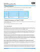
Application Note (Includes Differences for 970FX to 970MP) IBM PowerPC® 970MP RISC Microprocessor Preliminary 4. General Parameters Table 4-1 provides a summary of the general parameters for the PowerPC 970FX and 970MP. Table 4-1. General Parameters of the PowerPC 970FX and 970MP Item 970FX Description 970MP Description Die Size 66.2 sq. mm 153.8 sq. mm Die Dimensions 7.07mm x 9.36mm 13.225 mm x 11.
Preliminary Application Note (Includes Differences for 970FX to 970MP) IBM PowerPC® 970MP RISC Microprocessor scheme, with provisions for adjusting priorities when one core receives repeated serial retries. Logic in the BIU of each PU is modified to allow the arbiter to hold that PU from sending data to the PI bus when a transaction from the other processor is in progress.
Application Note (Includes Differences for 970FX to 970MP) IBM PowerPC® 970MP RISC Microprocessor Preliminary 5.1.1 1MB L2 Cache per Core The 970MP L2 cache design doubles the cache array size and capacity from 970FX, with a corresponding doubling in size of the two copies of the L2 tag arrays. Like the 970FX, it is an 8-way set associative cache of 128 B lines, but now consists of 1024 sets.
Preliminary Application Note (Includes Differences for 970FX to 970MP) IBM PowerPC® 970MP RISC Microprocessor 5.2 Processor Interconnect Bus The 970MP design incorporates an enhanced Processor Interconnect (PI) Interface for its high-speed off-chip bus. There are a number of changes to the physical interface and support hardware associated with the use of the enhanced definition from that in the 970FX.
Application Note (Includes Differences for 970FX to 970MP) IBM PowerPC® 970MP RISC Microprocessor Preliminary are transmitting ‘0’ bits. This process repeats itself until the 16 consecutive ‘1’ bits have been walked in sequence across all channels. The electrical shorts test mode is enabled by setting the following I/O SCOM mode register 0 bits: ESTMODE to ‘1’, WIAP to ‘1’, and RDTMODE to ‘1’. Once enabled the shorts test will create the sequential patterns across all data channels, and then will stop.
Preliminary Application Note (Includes Differences for 970FX to 970MP) IBM PowerPC® 970MP RISC Microprocessor If the expected results are not observed, an error is flagged in the status register. The DIAG_RDT vector out of the receiver provides observability of individual channel failures. The status register, bit 1, also indicates that the shorts test is complete.
Application Note (Includes Differences for 970FX to 970MP) IBM PowerPC® 970MP RISC Microprocessor Preliminary Section 11.4 of the 970FX User’s Manual are set to system dependent values during initialization, and must account for these larger latencies in the 970MP. The range of values that may be specified for each of these parameters for the 970MP is: Table 5-1. PowerPC 970MP Programmable Delay Parameters Parameter Min.
Application Note (Includes Differences for 970FX to 970MP) IBM PowerPC® 970MP RISC Microprocessor Preliminary 5.3 PowerTuning 5.3.1 Power Modes The twelve power states associated with the power tuning engine frequency scaling facility on the 970MP are indicated by the nodes S1 through S12 in Figure 5-2. Figure 5-2.
Application Note (Includes Differences for 970FX to 970MP) IBM PowerPC® 970MP RISC Microprocessor Preliminary Table 5-2 describes the twelve power mode states. Table 5-2. Power Mode States State Description S1 Full Run, High Speed S2 Doze, High Speed S3 Nap, High Speed S4 Deep Nap, High S5 Full Run, Medium Speed S6 Doze, Medium Speed S7 Nap, Medium Speed S8 Deep Nap, Medium S9 Full Run, Low Speed S10 Doze, Low Speed S11 Nap, Low Speed S12 Deep Nap, Low 5.3.
Application Note (Includes Differences for 970FX to 970MP) IBM PowerPC® 970MP RISC Microprocessor Preliminary The transition from quarter to full frequency is handled in two stages. First, the processor is transitioned from quarter frequency to half frequency using the quarter to half dither pattern. The processor is paused for 32 cycles at half frequency, and then transitioned to full frequency using the half to full dither pattern.
Application Note (Includes Differences for 970FX to 970MP) IBM PowerPC® 970MP RISC Microprocessor Preliminary 6. System Design Information The 970MP supports a 24:1 bus ratio for test purposes instead of the 16:1 bus ratio supported in the 970FX. The BUS_CFG(0:2) pin setting for this 24:1 bus ratio is ‘110’, which is the same setting that was used to select the 16:1 bus ratio in the 970FX. Unlike the 970FX, ANALOG_GND is not shorted to GND within the 970MP.
Application Note (Includes Differences for 970FX to 970MP) IBM PowerPC® 970MP RISC Microprocessor Preliminary 8.1.2 Capacitor Position The 970MP capacitors are rotated 90 degrees compared to the 970FX capacitor layout with respect to the A01 corner. This occurred since the PLL moved 90 degrees with respect to A01 and due to the die size of the 970MP - wider in the x direction than the 970FX because of the additional core.
Application Note (Includes Differences for 970FX to 970MP) IBM PowerPC® 970MP RISC Microprocessor Preliminary Table 8-4.
Preliminary Application Note (Includes Differences for 970FX to 970MP) IBM PowerPC® 970MP RISC Microprocessor Figure 8-1. PowerPC 970MP Mechanical Package (Side and Top View) Side View Top View Legend 1 DATUM A is the center plane of feature labeled DATUM A. 2 DATUM B is the center plane of feature labeled DATUM B. 3 Unless otherwise specified part is symmetrical about centerlines defined by DATUMs A and B.
Application Note (Includes Differences for 970FX to 970MP) IBM PowerPC® 970MP RISC Microprocessor Preliminary Figure 8-2. PowerPC 970MP Bottom Surface of CBGA Package (Bottom View) Legend 1 DATUM A is the center plane of feature labeled DATUM A. 2 DATUM B is the center plane of feature labeled DATUM B. 3 Unless otherwise specified part is symmetrical about centerlines defined by DATUMs A and B.
Application Note (Includes Differences for 970FX to 970MP) IBM PowerPC® 970MP RISC Microprocessor Preliminary Revision Log Revision November 15, 2006 Rev_Log.fm.1.0 November 15, 2006 Modification Version 1.0 Initial preliminary version.