
Eden/Ezra Processor User's Manual
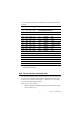
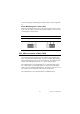

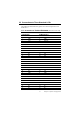
Table Of Contents
- Contents
- Chapter 1 General Information
- Chapter 2 Installation
- 2.1 Jumpers
- 2.2 Connectors
- 2.3 Locating jumpers
- 2.4 Locating Connectors
- 2.5 Setting Jumpers
- 2.6 Clear CMOS (JP4)
- 2.7 Installing DIMMs
- 2.8 IDE, CDROM hard drive connector (CN14, CN16)
- 2.9 Solid State Disk
- 2.10 Floppy drive connector (CN18)
- 2.11 Parallel port connector (CN15)
- 2.12 Keyboard and PS/2 mouse connector (CN25)
- 2.13 Power & HDD LED, Reset Button Connector (CN13, CN22)
- 2.14 Power connectors (CN27, CN5, FAN1)
- 2.15 ATX power control connector (CN3, CN23)
- 2.16 IR connector (CN24)
- 2.17 Audio interfaces (CN4, CN2)
- 2.18 COM port connector (CN19)
- 2.19 VGA/LCD/LVDS interface connections
- 2.20 TV-out interface (optional) (CN1)
- 2.21 Ethernet configuration
- 2.22 Watchdog timer configuration
- 2.23 USB connectors (CN20, CN28)
- Chapter 3 Software Configuration
- Chapter 4 Award BIOS Setup
- 4.1 System test and initialization
- 4.2 Award BIOS setup
- 4.2.1 Entering setup
- 4.2.2 Standard CMOS Features setup
- 4.2.3 Advanced BIOS Features setup
- 4.2.4 Advanced Chipset Features setup
- 4.2.5 Integrated Peripherals
- 4.2.6 Power Management Setup
- 4.2.7 PnP/PCI Configurations
- 4.2.8 PC Health Status
- 4.2.9 Frequency/Voltage Control
- 4.2.10 Load Optimized Defaults
- 4.2.11 Set Password
- 4.2.12 Save & Exit Setup
- 4.2.13 Exit Without Saving
- Chapter 5 PCI SVGA Setup
- Chpater 6 Audio Setup
- Chapter 7 PCI Bus Ethernet Interface
- Appendix A Programming the Watchdog Timer
- Appendix B Installing PC/104-Plus Modules
- Appendix C Pin Assignments
- C.1 CPU Fan Power Connector (FAN 1)
- C.2 Ethernet 10/100Base-T Connector (CN12)
- C.3 Audio Connector (CN4)
- C.4 Audio In Connector (CN2)
- C.5 Main Power Connector (CN5)
- C.6 Keyboard and PS/2 Mouse Connector (CN25)
- C.7 Floppy Disk Drive Connector (CN18)
- C.8 PC/104 plus Connectors (CN17)
- C.9 IDE Hard Drive Connector (CN14, CN16)
- C.10 Parallel Port Connector (CN15)
- C.11 Power & HDD LED Connector(CN13)
- C.12 Reset Button Connector (CN22)
- C.13 USB Connector (CN20, CN28)
- C.14 LCD Inverter Backlight Connector (CN6)
- C.15 IR Connector (CN24)
- C.16 CRT Display Connector (CN8)
- C.17 TV (video) Out Connector (CN1)
- C.18 Flat Panel Connector (CN11)
- C.19 Extended Flat Panel Display Connector (CN10)
- C.20 LCD Signal Mapping
- C.21 LVDS Connector (CN9)
- C.22 Peripheral Power Connector (CN27)
- C.23 COM Port Connector (CN19)
- C.24 CompactFlash Card Connector (CN26)
- C.25 ATX Power Feature Connector (CN3)
- Appendix D System Assignments
- Appendix E Optional Extras for the PCM-9575
- Appendix F Mechanical Drawings

21 Chapter 2 Installation
S1 is an 8 segment DIP switch for DSTN/TFT panel type and resolution
functions.
2.20 TV-out interface (optional) (CN1)
The PCM-9575 board provides optional TV-out via CN1. This consists of
a 5-pin wafer box header. Output supports composite video and S-video
connectors via an optional cable kit (p/n: 1103050306). TV-out genera-
tors use both NTSC and PAL formats.
To set up your video interface:
1. Run the appropriate installation program located on the utility disk.
That’s all there is to it.
Table 2.4: S1 Panel Type select
SW
1-1
SW
1-2
SW
1-3
SW
1-4 Panel Type & Resolution
ON ON ON ON TFT 640x480** 18bit (H. V. Freq)
ON ON ON OFF TFT 648x480 18bit (Synthetic)
ON ON OFF ON TFT 648x480** N/A
ON ON OFF OFF TFT 648x480** LVDS
ON OFF ON ON DSTN 648x480** 18bit
ON OFF ON OFF TFT 800x600** 18bit (H. V. Freq)
ON OFF OFF ON TFT 800x600* 18bit (Synthetic)
ON OFF OFF OFF TFT 800x600 LVDS
OFF ON ON ON TFT 800x600** N/A
OFF ON ON OFF DSTN 800x600** 18bit
OFF ON OFF ON TFT 1024x768** 36bit (H. V. Freq)
OFF ON OFF OFF TFT 1024x768 36bit (Synthetic)
OFF OFF ON ON TFT 1024x768** LVDS
OFF OFF ON OFF TFT 1024x768** N/A
OFF OFF OFF ON DSTN 1024x768** 18bit
OFF OFF OFF OFF DSTN 1024x768** 24bit
* Default setting
** will support in the future