
Eden/Ezra Processor User's Manual
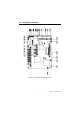
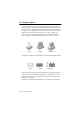
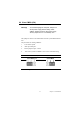
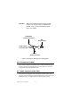
Table Of Contents
- Contents
- Chapter 1 General Information
- Chapter 2 Installation
- 2.1 Jumpers
- 2.2 Connectors
- 2.3 Locating jumpers
- 2.4 Locating Connectors
- 2.5 Setting Jumpers
- 2.6 Clear CMOS (JP4)
- 2.7 Installing DIMMs
- 2.8 IDE, CDROM hard drive connector (CN14, CN16)
- 2.9 Solid State Disk
- 2.10 Floppy drive connector (CN18)
- 2.11 Parallel port connector (CN15)
- 2.12 Keyboard and PS/2 mouse connector (CN25)
- 2.13 Power & HDD LED, Reset Button Connector (CN13, CN22)
- 2.14 Power connectors (CN27, CN5, FAN1)
- 2.15 ATX power control connector (CN3, CN23)
- 2.16 IR connector (CN24)
- 2.17 Audio interfaces (CN4, CN2)
- 2.18 COM port connector (CN19)
- 2.19 VGA/LCD/LVDS interface connections
- 2.20 TV-out interface (optional) (CN1)
- 2.21 Ethernet configuration
- 2.22 Watchdog timer configuration
- 2.23 USB connectors (CN20, CN28)
- Chapter 3 Software Configuration
- Chapter 4 Award BIOS Setup
- 4.1 System test and initialization
- 4.2 Award BIOS setup
- 4.2.1 Entering setup
- 4.2.2 Standard CMOS Features setup
- 4.2.3 Advanced BIOS Features setup
- 4.2.4 Advanced Chipset Features setup
- 4.2.5 Integrated Peripherals
- 4.2.6 Power Management Setup
- 4.2.7 PnP/PCI Configurations
- 4.2.8 PC Health Status
- 4.2.9 Frequency/Voltage Control
- 4.2.10 Load Optimized Defaults
- 4.2.11 Set Password
- 4.2.12 Save & Exit Setup
- 4.2.13 Exit Without Saving
- Chapter 5 PCI SVGA Setup
- Chpater 6 Audio Setup
- Chapter 7 PCI Bus Ethernet Interface
- Appendix A Programming the Watchdog Timer
- Appendix B Installing PC/104-Plus Modules
- Appendix C Pin Assignments
- C.1 CPU Fan Power Connector (FAN 1)
- C.2 Ethernet 10/100Base-T Connector (CN12)
- C.3 Audio Connector (CN4)
- C.4 Audio In Connector (CN2)
- C.5 Main Power Connector (CN5)
- C.6 Keyboard and PS/2 Mouse Connector (CN25)
- C.7 Floppy Disk Drive Connector (CN18)
- C.8 PC/104 plus Connectors (CN17)
- C.9 IDE Hard Drive Connector (CN14, CN16)
- C.10 Parallel Port Connector (CN15)
- C.11 Power & HDD LED Connector(CN13)
- C.12 Reset Button Connector (CN22)
- C.13 USB Connector (CN20, CN28)
- C.14 LCD Inverter Backlight Connector (CN6)
- C.15 IR Connector (CN24)
- C.16 CRT Display Connector (CN8)
- C.17 TV (video) Out Connector (CN1)
- C.18 Flat Panel Connector (CN11)
- C.19 Extended Flat Panel Display Connector (CN10)
- C.20 LCD Signal Mapping
- C.21 LVDS Connector (CN9)
- C.22 Peripheral Power Connector (CN27)
- C.23 COM Port Connector (CN19)
- C.24 CompactFlash Card Connector (CN26)
- C.25 ATX Power Feature Connector (CN3)
- Appendix D System Assignments
- Appendix E Optional Extras for the PCM-9575
- Appendix F Mechanical Drawings

15 Chapter 2 Installation
(See your hard drive’s documentation for the location of the con-
nector.)
If desired, connect a second drive as described above.
Unlike floppy drives, IDE hard drives can connect to either end of the
cable. If you install two drives, you will need to set one as the master and
one as the slave by using jumpers on the drives. If you install only one
drive, set it as the master.
2.9 Solid State Disk
The PCM-9575 provides a CompactFlash™ card socket and DiskOnChip
socket for Solid state disk solutions.
2.9.1 CompactFlash (CN26)
The CompactFlash card shares a secondary IDE channel which can be
enabled/disabled via the BIOS settings.
2.10 Floppy drive connector (CN18)
You can attach up to two floppy drives to the PCM-9575’s on-board con-
troller. You can use any combination of 5.25” (360 KB and 1.2 MB) and/
or 3.5” (720 KB, 1.44 MB, and 2.88 MB) drives.
A 34-pin daisy-chain drive connector cable is required for a dual-drive
system. On one end of the cable is a 34-pin flat-cable connector. On the
other end are two sets of floppy disk drive connectors. Each set consists
of a 34-pin flat-cable connector (usually used for 3.5” drives) and a
printed-circuit board connector (usually used for 5.25” drives).
2.10.1 Connecting the floppy drive
1. Plug the 34-pin flat-cable connector into CN18. Make sure that the
red wire corresponds to pin one on the connector.
2. Attach the appropriate connector on the other end of the cable to
the floppy drive(s). You can use only one connector in the set. The
set on the end (after the twist in the cable) connects to the A: drive.
The set in the middle connects to the B: drive.
3. If you are connecting a 5.25” floppy drive, line up the slot in the
printed circuit board with the blocked-off part of the cable connec-
tor.