
Eden/Ezra Processor User's Manual
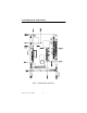

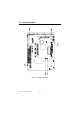
Table Of Contents
- Contents
- Chapter 1 General Information
- Chapter 2 Installation
- 2.1 Jumpers
- 2.2 Connectors
- 2.3 Locating jumpers
- 2.4 Locating Connectors
- 2.5 Setting Jumpers
- 2.6 Clear CMOS (JP4)
- 2.7 Installing DIMMs
- 2.8 IDE, CDROM hard drive connector (CN14, CN16)
- 2.9 Solid State Disk
- 2.10 Floppy drive connector (CN18)
- 2.11 Parallel port connector (CN15)
- 2.12 Keyboard and PS/2 mouse connector (CN25)
- 2.13 Power & HDD LED, Reset Button Connector (CN13, CN22)
- 2.14 Power connectors (CN27, CN5, FAN1)
- 2.15 ATX power control connector (CN3, CN23)
- 2.16 IR connector (CN24)
- 2.17 Audio interfaces (CN4, CN2)
- 2.18 COM port connector (CN19)
- 2.19 VGA/LCD/LVDS interface connections
- 2.20 TV-out interface (optional) (CN1)
- 2.21 Ethernet configuration
- 2.22 Watchdog timer configuration
- 2.23 USB connectors (CN20, CN28)
- Chapter 3 Software Configuration
- Chapter 4 Award BIOS Setup
- 4.1 System test and initialization
- 4.2 Award BIOS setup
- 4.2.1 Entering setup
- 4.2.2 Standard CMOS Features setup
- 4.2.3 Advanced BIOS Features setup
- 4.2.4 Advanced Chipset Features setup
- 4.2.5 Integrated Peripherals
- 4.2.6 Power Management Setup
- 4.2.7 PnP/PCI Configurations
- 4.2.8 PC Health Status
- 4.2.9 Frequency/Voltage Control
- 4.2.10 Load Optimized Defaults
- 4.2.11 Set Password
- 4.2.12 Save & Exit Setup
- 4.2.13 Exit Without Saving
- Chapter 5 PCI SVGA Setup
- Chpater 6 Audio Setup
- Chapter 7 PCI Bus Ethernet Interface
- Appendix A Programming the Watchdog Timer
- Appendix B Installing PC/104-Plus Modules
- Appendix C Pin Assignments
- C.1 CPU Fan Power Connector (FAN 1)
- C.2 Ethernet 10/100Base-T Connector (CN12)
- C.3 Audio Connector (CN4)
- C.4 Audio In Connector (CN2)
- C.5 Main Power Connector (CN5)
- C.6 Keyboard and PS/2 Mouse Connector (CN25)
- C.7 Floppy Disk Drive Connector (CN18)
- C.8 PC/104 plus Connectors (CN17)
- C.9 IDE Hard Drive Connector (CN14, CN16)
- C.10 Parallel Port Connector (CN15)
- C.11 Power & HDD LED Connector(CN13)
- C.12 Reset Button Connector (CN22)
- C.13 USB Connector (CN20, CN28)
- C.14 LCD Inverter Backlight Connector (CN6)
- C.15 IR Connector (CN24)
- C.16 CRT Display Connector (CN8)
- C.17 TV (video) Out Connector (CN1)
- C.18 Flat Panel Connector (CN11)
- C.19 Extended Flat Panel Display Connector (CN10)
- C.20 LCD Signal Mapping
- C.21 LVDS Connector (CN9)
- C.22 Peripheral Power Connector (CN27)
- C.23 COM Port Connector (CN19)
- C.24 CompactFlash Card Connector (CN26)
- C.25 ATX Power Feature Connector (CN3)
- Appendix D System Assignments
- Appendix E Optional Extras for the PCM-9575
- Appendix F Mechanical Drawings
PCM-9575 User’s Manual 4
• Enhanced IDE interface: Two channels supports up to four EIDE
devices. BIOS auto-detect, PIO Mode 3 or Mode 4, UDMA 33
transfer. Primary IDE support up to UDMA 66/100 mode
• FDD interface: Supports up to two FDDs
• Serial ports: Four serial RS-232 ports, COM1, 3, 4: RS-232, COM2:
RS-232/422/485
• Parallel port: One parallel port, supports SPP/EPP/ECP mode
• Infrared port: Shared with COM2. Transfer rates up to 115Kbps
• Keyboard/mouse connector: Supports standard PC/AT keyboard and a
PS/2 mouse
• Power management: Supports power saving modes including Normal/
Standby/Suspend modes. APM 1.2 compliant
• Watchdog timer: 62 level timer intervals
• USB: Two universal serial bus ports (4 USB port option)
• Expansion: One PCI slot and PC/104 plus connector for ISA and PCI
control board
• Solid State Disk
Supports one 50-pin socket for CFC type I/II
Supports M-Systems DOC
®
2000
1.3.2 VGA/LCD Interface
•
Chipset:
VIA Twister chip with integrated Savage4 2D/3D/Video Accelerator
•
Frame buffer:
Supports 8/16/32 MB frame buffer with system memory
• Interface: 4X AGP VGA/LCD interface, Support for 9, 12, 15, 18, 24,
36 bit TFT and optional 16- or 24-bit DSTN panel
• Display mode: CRT Modes: 1280 x 1024@32bpp (60Hz), 1024 x 768
@ 32bpp (85 Hz); LCD/Simultaneous Modes: 1280 x 1024 @16bpp
(60 Hz), 1024 x 768 @16bpp (60Hz)
1.3.3 LVDS: Supports 2 Channel (2 x 18 bit) LVDS interface
•
Chipset:
VIA VT8606T (TwisterT)
1.3.4 Audio function
• Chipset: VIA 82C686 South Bridge
• Audio controller: AC97 Ver. 2.0 compliant interface, Multistream
Direct sound and Direct Sound 3D acceleration
• Stereo sound: 8-bit full-duplex
• Audio interface: Microphone in, Line in, CD audio in; Line out,
Speaker L, Speaker R
• Power: Accepts +12 V source for improved audio quality
1.3.5 TV-out (optional)
• Chipset: VIA VT 1621
Supports NTSC, NTSC=EIA (Japan) and PAL TV formats