PC-CARD-DAS16/16AO Analog I/O and Digital I/O Board User’s Guide Document Revision 1, April, 2007 © Copyright 2007, Measurement Computing Corporation
Your new Measurement Computing product comes with a fantastic extra — Management committed to your satisfaction! Refer to www.mccdaq.com/execteam.html for the names, titles, and contact information of each key executive at Measurement Computing. Thank you for choosing a Measurement Computing product—and congratulations! You own the finest, and you can now enjoy the protection of the most comprehensive warranties and unmatched phone tech support.
Trademark and Copyright Information TracerDAQ, Universal Library, Harsh Environment Warranty, Measurement Computing Corporation, and the Measurement Computing logo are either trademarks or registered trademarks of Measurement Computing Corporation. Windows, Microsoft, and Visual Studio are either trademarks or registered trademarks of Microsoft Corporation LabVIEW is a trademark of National Instruments. CompactFlash is a registered trademark of SanDisk Corporation.
Table of Contents Preface About this User's Guide .......................................................................................................................7 What you will learn from this user's guide .........................................................................................................7 Conventions in this user's guide .........................................................................................................................7 Where to find more information....
PC-CARD-DAS16/16AO User's Guide Interrupt ............................................................................................................................................................22 Counter .............................................................................................................................................................23 Power consumption ............................................................................................................................
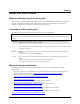
Preface About this User's Guide What you will learn from this user's guide This user's guide explains how to install, configure, and use the PC-CARD-DAS16/16AO so that you get the most out of its analog I/O, digital I/O and counter features. This user's guide also refers you to related documents available on our web site, and to technical support resources.
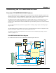
Chapter 1 Introducing the PC-CARD-DAS16/16AO Overview: PC-CARD-DAS16/16AO features The PC-CARD-DAS16/16AO is a data acquisition and control board for IBM PC compatible computers with PCMCIA type II slots. The PC-CARD-DAS16/16AO provides 16 single-ended or 8 differential analog inputs, 16-bit A/D resolution, two analog outputs, four digital I/O lines, and three 16-bit down counters. The analog input range is fully programmable in one of four bipolar ranges.
PC-CARD-DAS16/16AO User's Guide Introducing the PC-CARD-DAS16/16AO Software features For information on the features of InstaCal and the other software included with your PC-CARDDAS16/16AO, refer to the Quick Start Guide that shipped with your device. The Quick Start Guide is also available in PDF at www.mccdaq.com/PDFmanuals/DAQ-Software-Quick-Start.pdf. Check www.mccdaq.com/download.htm for the latest software version.
Chapter 2 Installing the PC-CARD-DAS16/16AO What comes with your PC-CARD-DAS16/16AO shipment? The following items are shipped with the PC-CARD-DAS16/16AO. Hardware PC-CARD-DAS16/16AO Additional documentation In addition to this hardware user's guide, you should also receive the Quick Start Guide (available in PDF at www.mccdaq.com/PDFmanuals/DAQ-Software-Quick-Start.pdf).
PC-CARD-DAS16/16AO User's Guide Installing the PC-CARD-DAS16/16AO Unpacking the PC-CARD-DAS16/16AO As with any electronic device, you should take care while handling to avoid damage from static electricity. Before removing the PC-CARD-DAS16/16AO from its packaging, ground yourself using a wrist strap or by simply touching the computer chassis or other grounded object to eliminate any stored static charge.
PC-CARD-DAS16/16AO User's Guide Installing the PC-CARD-DAS16/16AO 2. Select the Hardware tab and click on the Device Manager button. 3. Verify that "PCMCIA adapters" is listed in the Device Manager. If you don’t find this entry, or if the properties for the adapter indicate "this device is not working," you need to install or update your PCMCIA adapter drivers. o If the PCMCIA adapter is not listed, use the Add New Hardware Wizard to install PCMCIA support.
PC-CARD-DAS16/16AO User's Guide Installing the PC-CARD-DAS16/16AO Cabling Measurement Computing offers two cables for connecting the PC-CARD-DAS16/16AO to a screw-type terminal board or other signal conditioning interface board: The CPCC-50F-39 cable: 39 inches (990 mm) long; compatible with standard 50-pin screw terminal products. The CPCC-50M-4 cable: four-inch long adapter cable; required when using a C50FF-x series cable.
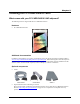
PC-CARD-DAS16/16AO User's Guide Installing the PC-CARD-DAS16/16AO Caution! Do not exceed the input specifications. There are no socketed or user serviceable parts in a PCCARD-DAS16/16AO. Check the specifications and input voltages before connecting any signals. CPCC-50F-39 49 50 50 Key 1 Dot 1 2 50-pin micro connector. Connect to the I/O connector on the PC-CARD with the dot facing UP. 50-pin female IDC connector. Figure 6.
PC-CARD-DAS16/16AO User's Guide Installing the PC-CARD-DAS16/16AO C50FF-x 2 1 50 49 The red stripe identifies pin # 1 50-pin female IDC connector 2 1 50 49 50-pin female IDC connector Figure 8. C50FF-x cable Details on the C50FF-x cable are available on our web site at www.mccdaq.com/cbicatalog/cbiproduct.asp?dept_id=104&pf_id=136.
Chapter 3 Programming and Developing Applications After following the installation instructions in Chapter 2, your board should now be installed and ready for use. In general there may be no correspondence among registers for different boards. Software written at the register-level for other models does not function correctly with your board. Programming languages Measurement Computing’s Universal Library provides access to board functions from a variety of Windows programming languages.
Chapter 4 Functional Details Analog input resolution and range The 16-bit A/D converter provides a resolution of 1/65,536 parts of full scale. The smallest reading of full scale (1 part in 65,536) is called a Least Significant Bit (LSB). Four different bipolar ranges are controlled by software: Analog input ranges Bipolar 1 LSB ±10 V ±5 V ±2.5 V ±1.25 V 0.000305 V 0.000153 V 0.000076 V 0.000038 V The input range is controlled by a programmable-gain amplifier.
PC-CARD-DAS16/16AO User's Guide Functional Details After a conversion is made, the sample is stored in a 4096-word (sample) FIFO buffer from which it may be retrieved one sample at a time or in blocks via REP-INSW transfers. How does the FIFO size and design affect throughput? The 4096-sample FIFO buffer stores samples from the A/D converter as they are being converted. When a block of samples is ready and when the PC is ready, the FIFO is emptied into system memory.
Chapter 5 Specifications Typical for 25 °C unless otherwise specified. Specifications in italic text are guaranteed by design. Analog input Table 1. Analog input specifications A/D converter type Resolution Number of channels Input ranges A/D pacing (software programmable) A/D trigger sources A/D triggering modes A/D gate sources Burst mode Data transfer A/D conversion time Calibrated throughput Calibration AD976A 16 bits 16 single-ended / 8 differential, software selectable ±10 V, ±5 V, ±2.5 V, ±1.
PC-CARD-DAS16/16AO User's Guide Specifications Table 3. Calibrated accuracy specifications (Note 1) Range Gain Error Offset Error DLE ±10.00 V ±5.000 V ±2.500 V ±1.250 V ±3 max ±3 max ±3 max ±3 max ±1.5 max ±1.5 max ±1.5 max ±1.5 max -1.0, +1.75 max -1.0, +1.75 max -1.0, +1.75 max -1.0, +1.75 max ILE (Note 1) ±2.0 max ±2.0 max ±2.0 max ±2.0 max Note 1: These are the intrinsic specifications of the ADC. Software calibration may introduce a small additional amount of linearity error.
PC-CARD-DAS16/16AO User's Guide Specifications Analog output Table 6. Analog output specifications D/A converter type Resolution Number of channels Configuration Output range D/A pacing Data transfer Throughput LTC1655 16 bits 2 Voltage output, single-ended ±10 V Software Programmed I/O System dependent. Using the Universal Library programmed output function (cbAout) in a loop in Visual Basic, a typical update rate of 1.5 kHz (±200 Hz) can be expected.
PC-CARD-DAS16/16AO User's Guide Miscellaneous Specifications Double buffered output latches Coding: Offset Binary (0 code = -FS, 65535 code = +FS) Output voltage on power up and reset: -10 V (-FS) Digital input/output Table 9. DIO specifications Digital type Number of I/O Configuration Input low voltage Input high voltage Output low voltage (IOL = 4 mA) Output high voltage (IOH = -4 mA) Absolute maximum input voltage Power-up / reset state FPGA 4 One port, programmable 4 input or 4 output 0.8 V max 2.
PC-CARD-DAS16/16AO User's Guide Specifications Counter Table 11.
PC-CARD-DAS16/16AO User's Guide Specifications Environmental Table 14. Environmental specifications 0 to 70 °C -40 to 100 °C 0 to 95% non-condensing Operating temperature range Storage temperature range Humidity Mechanical Table 15. Mechanical specifications Card dimensions PCMCIA type II: 85.6 mm (L) x 54.0 mm (W) x 5.0 mm (H) Connector and pin out Table 16.
PC-CARD-DAS16/16AO User's Guide Specifications Table 18.
Declaration of Conformity Manufacturer: Address: Category: Measurement Computing Corporation 10 Commerce Way Suite 1008 Norton, MA 02766 USA Electrical equipment for measurement, control and laboratory use.
Measurement Computing Corporation 10 Commerce Way Suite 1008 Norton, Massachusetts 02766 (508) 946-5100 Fax: (508) 946-9500 E-mail: info@mccdaq.com www.mccdaq.