NH2025-10 High Density Workgroup Switch Installation and User Guide
Standards Compliance UL 1950; CSA 22.2 No 950; VCCI; FCC Part 15 Class A; CE-89/336/EEC, 73/23/EEC FCC Notice WARNING: This equipment has been tested and found to comply with the limits for a Class A digital device, pursuant to Part 15 of the FCC Rules. These limits are designed to provide reasonable protection against harmful interference when the equipment is operated in a commercial environment.
Contents Overview Applications ............................................................................................................................... 2 Network Management Systems................................................................................................. 2 Feature Summary...................................................................................................................... 3 Performance/Configuration ...............................................................
Configuring, Modifying, and Monitoring the Unit Console Commands..................................................................................................................17 System Commands...................................................................................................................20 IP Commands...........................................................................................................................23 IP Configuration ............................................
Virtual Networking.................................................................................................................. 45 Important Considerations ................................................................................................. 46 Viewing the VLAN Mode................................................................................................... 46 Setting the VLAN Mode ....................................................................................................
Viewing the Authentication Trap Status ...........................................................................59 Setting the Authentication Trap ........................................................................................59 Configuring the Trap Stations...........................................................................................60 Statistics ..................................................................................................................................
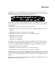
Overview The NH2025-10 is a robust switch platform, representing the next generation in switching technology. It boasts a combination of cutting-edge hardware architecture, a rich set of Virtual LAN (VLAN) options and advanced network management features. Figure 1 - General View The NH2025-10 contains a built-in SNMP agent running on the SNMP Processor Board. This allows each unit to be managed from a centralized management station through any SNMPcompliant NMS.
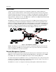
Overview Applications A switch boosts network performance by segmenting a single large collision domain into smaller, separate collision domains. It also provides dedicated connections for heavily loaded networks using work stations and servers. In addition, the Full Duplex capability of Ethernet switches permits long distance connectivity for backbone applications or high throughput for high-performance dedicated servers.
Overview Feature Summary The following are the Performance/Configuration and Management features supported on the NH2025-10 switch. Performance/Configuration • 24 switched 10/100Mbps ports and a dport to accommodate one of the following uplink modules: − Single Gigabit Ethernet port (MM,SM) − Dual Gigabit Ethernet ports (MM,SM)* − 8 10/100 auto-negotiation ports module − 2 100Base-FX ports (MM,SM) • The highest common port speed is automatically set when connecting any standard compliant (802.
Installing and Setting Up the Unit The NH2025-10 can operate as a stand-alone unit or in conjunction with any of NBase-Xyplex’s other Ethernet offerings. Switch management is through NBase-Xyplex MegaVision software, any SNMP-compatible NMS, or through the Command Line Interface (CLI). Installing the Unit This section outlines the installation and operation of the NH2025-10. The NH2025-10 comes as a 19” rack-mountable unit.
Installing and Setting Up the Unit 1 Global LEDs PWR Green ON indicates Power ON MGMT Blinking Green indicates that the firmware is initializing Solid Green indicates that firmware is installed and in proper operational mode 2 10/100 Port LEDs L Solid Green indicates a valid connection. During LINK test, there is an intermittent flash on all the ports. A Solid Green indicates network activity.
Installing and Setting Up the Unit Modules for NH 2025-10 Figure 5 - Front Panels of the EM2003-1GE and EM2003-2FO Uplink Modules EM2003-1GE One 1000BaseLX port (SM 1500nm, .0-60km) EM2003-1GE LEDs L Green ON = Link, OFF = No Link A Green ON = Activity, OFF = No Activity Type Connector Wavelength Budget Estimated Range Attenuation Minimum Committed Power SX/M DSC 850nm NA 0–350 km 3 dB/km -9.5 dBm LX/M DSC 1310nm NA 0–500 km 2 dB/km -13 dBm LX/S1 DSC 1310nm NA 0–6 km 0.
Installing and Setting Up the Unit Figure 6 - Front Panels of the EM2003-8TP and EM2025-2GE* Modules EM2003-8TP EM2003-8TP Eight port 10/100Base-TX switch module L Green ON = Link, OFF = No Link A Green ON = Activity, OFF = No Activity Em2003-2GE* EM2003-2GE* Two port Gigabit 1000Base-SX (MM, 850nm, 0-350m) *Future release L Green ON = Link, OFF = No Link A Green ON = Activity, OFF = No Activity Connecting Power to the Unit The power cord should be plugged into an easily accessible outlet.
Installing and Setting Up the Unit Grounding Reliable grounding of this equipment must be maintained. Particular attention should be given to electrical connections when connecting to a power strip, rather than direct connections to the electrical outlet. Connecting Ethernet Devices For optimum performance, the Ethernet segments connected to the NH2025-10 must be configured carefully.
Getting Started This section describes how to connect to the management port, log into the Command Line Interface, and set the unit’s IP Address. Connecting to the Management Port With the product we supply a management cable. You can use it to get access to the management port. To configure the serial ports do the following items: 1. Connect the cable provided to the management port and communication interface (COM1 or COM2) of your PC. 2.
Getting Started NOTE: If the switch has no IP Address, then the provided IP Configuration changes the running parameters as well as the NVRAM-based database. If the switch was already configured, the command only changes the NVRAM database. Therefore, to use the new parameters you should reset the Switch, using the warm-reset command. You can also use the set-ip command to accomplish this. When you do, the mask and broadcast are automatically set to defaults according to the IP address class.
Using the Command Line Interface This section describes how to use the Command Line Interface (CLI) to configure and manage the NH2025-10 switch. Command Conventions The following conventions are used within this guide to make understanding and using the CLI easier. Command Items appearing in this typeface are to be typed as shown. Italics Italicized items are variables and represent values. For example, represents an IP address in dotted decimal notation as 123.1.2.3.
Using the Command Line Interface Example SYS_console> ping 129.1.1.7 ? The unit displays the next level of parameters: ping IP traffic generator [arg #0] destination IP address [arg #1] number of packets to send or 0 for endless ping SYS_console> ping 129.1.1.7 Getting Command Group Help To find out the command groups that are available within the unit, enter a question mark at the CLI prompt. The CLI displays a list of all of the available command groups and a short explanation of each.
Using the Command Line Interface Example SYS_console>get-c? command ‘get-c’ not found Commands matching get-comm show current read or/and write community get-con-matrix retrieves the VLAN connectivity matrix get-colls-cnt gets the collision distribution counters per port SYS_console>get-co Retrieving Command History The CLI allows you to retrieve a history of the last commands you have issued.
Using the Command Line Interface Command Line Errors The CLI displays messages when you enter a command incorrectly. The following command line error messages are used: • • Nonexistent command Incorrect number of parameters Nonexistent Command If you enter a command incorrectly or if the command does not exist, the CLI returns an error message indicating the type of error that occurred.
Configuring, Modifying, and Monitoring the Unit You can configure, modify, and monitor the unit using the following categories of commands: • • Console System • • • IP configuration SNMP Agent Switching database and database entry management • • Virtual LAN EtherChannel • • • Port Configuration Switching Statistics Spanning Tree Refer to Appendix A for a quick reference of the available commands. Console Commands Console commands allow you to configure the CLI parameters and user interface.
Configuring, Modifying, and Monitoring the Unit banner The banner command displays the Nbase-Xyplex CLI logo. clear The clear command clears the screen and displays the CLI prompt. login The login command exits the CLI, but does not disconnect a Telnet session. This allows you to test a password (or other activity) without reconnecting. logout The logout command ends the actual CLI Session. To use the CLI, you must login again. set-page The set-page command sets the console page size (in lines per page).
Configuring, Modifying, and Monitoring the Unit set-passwd The console requires you enter a password to log in. The set-passwd command allows you to change the console password. To change the console password: 1. Enter the set-passwd command at the CLI prompt. The system prompts you for the old password. 2. Enter the old password. The system prompts you for a new password. 3. Enter your new password. Note that the password is not echoed back to you. The system prompts you to reenter the new password. 4.
Configuring, Modifying, and Monitoring the Unit System Commands System Commands allow you to display and set the system-related parameters. To view the system commands, enter system at the CLI prompt. The following are the available system commands. sys-stat The sys-stat command displays general status information about the Ethernet Switch, and its SNMP Agent Hardware and Software. Example SYS_console>sys-stat NBase-Xyplex Nh2025-10 Version 1.08 Mon Apr 26 16:09:47 1999 SNMP Object ID is : < 1.3.6.1.4.1.
Configuring, Modifying, and Monitoring the Unit get-stst-level The get-stst-level command displays the self-test level (Disable or Enable) of the device. The default value is Enable. set-stst-level The set-stst-level command sets the self-test level of the device. There are two levels of self-test: Disable and Enable. The self-test level is stored in NVRAM. To set the self-test level, use the following command: set-stst-level warm-reset The warm-reset command resets the SNMP Agent software.
Configuring, Modifying, and Monitoring the Unit get-tftp-srvr The get-tftp-srvr command retrieves the IP address of the TFTP server that the Agent uses to download software. Refer to the sw-dnld command for further information. set-tftp-srvr The set-tftp-srvr command sets the IP address of the TFTP server used for downloading. To set the IP address of the TFTP server, use the following command: set-tftp-srvr set-tftp-mode The set-tftp-mode command sets the TFTP download mode.
Configuring, Modifying, and Monitoring the Unit IP Commands This section lists the IP Configuration commands available at the CLI. It is separated into the following command sections: • IP configuration • • Address Resolution Protocol (ARP) Bootp • Ping To view the IP commands, enter IP at the CLI prompt. The following are the available IP commands. IP Configuration get-ip The get-ip command shows the device’s current IP address, if any.
Configuring, Modifying, and Monitoring the Unit Setting an IP address set-ip The set-ip command sets the IP address of the SNMP Agent. If no IP address was previously set (as is the factory default configuration), the new value is used immediately and saved into NVRAM. Otherwise the new value is only stored in the NVRAM, and the user must execute a warm-reset to effect the change. set-ip set-ip-cfg The set-ip-cfg command sets the IP address, network IP mask, and broadcast IP address.
Configuring, Modifying, and Monitoring the Unit Erasing an IP Configuration clear-ip-cfg The clear-ip-cfg command clears the NVRAM IP configuration. Example SYS_console>clear-ip-cfg Device IP Configuration cleared SYS_console> Configuring a Gateway get-gatew The get-gatew command shows the default gateway address. Example SYS_console>get-gatew The default gateway address is : 194.001.001.001 SYS_console> set-gatew The get-gatew command sets the default gateway IP Address.
Configuring, Modifying, and Monitoring the Unit To activate/deactivate bootp use the following commands: set-bootp — Enables or disables the bootp process activation. get-bootp — Retrieves the state of the bootp process. Address Resolution Protocol (ARP) To view the ARP commands, enter ARP at the CLI prompt. The following are the available ARP commands. get-arp-tbl The get-arp-tbl command displays the ARP table.
Configuring, Modifying, and Monitoring the Unit get-arp-stats The get-arp-stats command gets ARP statistics. Example SYS_console>get-arp-stats InMsgs: : 0 InErrors : 0 InIllegals : 0 InBadOpcode : 0 InRequests : 0 InReplies : 0 InReqNotForMe : 0 OutMsgs : 0 OutErrors : 0 OutRequests : 0 OutReplies : 0 ResolveReqs : 0 SYS_console> Port configuration This section contains commands for configuring and displaying the ports’ parameters with the Administrative Interface.
Configuring, Modifying, and Monitoring the Unit • PORT_ID: An interface number specified in the form of 1-25 (dport). • LAN_TYPE: − ETH-10/100 − ETH1000 indicates Gigabit Ethernet • LINK: ON/OFF if ON a device is connected to the port and the link is UP • IF TYPE: TP (twisted pair)/FO (fiber optic) • SPEED_SEL: AUTO/FORC10/100/1000 • LAN_SPEED: The actual speed that has been negotiated between the entities.
Configuring, Modifying, and Monitoring the Unit Setting the flow control Ports are compliant to flow control specifications 802.3x or back-pressure. You can set a port to perform flow control only if this port is in full duplex mode otherwise backpressure is applied to control the incoming flow of data. When the port is configured to do 802.3z flow control the switching engine sends a continuous flow of idle frames to avoid dead locks.
Configuring, Modifying, and Monitoring the Unit EtherChannel The EtherChannel feature is also known under the name of Port Trunking. It allows equipment to pass data through multiple physical links. Providing an extended bandwidth and redundancy. NOTE: If you want to use this feature in conjunction with VLAN be aware that you must set exactly the same VLAN configuration for each physical link that belongs to the EtherChannel group.
Configuring, Modifying, and Monitoring the Unit Example SYS_telnet>new-ec run 23-24 RUN:OK Ethernet Channel Table from RUN database =========================================== Ether-Channel-ID Ports =========================================== 1 23 24 Deleting the EtherChannel Configuration del-ec The del-ec command deletes the trunk port configuration.
Configuring, Modifying, and Monitoring the Unit Get Port Priority get-priority-port-cfg The get-priority-port-cfg command retrieves the port priority configuration. Example SYS_telnet>get-priority-port-cfg Ports Priority Configuration : 1- 8 2- 1 3- 1 4- 1 9- 1 10- 1 11- 1 12- 1 17- 1 18- 1 19- 1 20- 1 5- 1 13- 1 21- 1 6- 1 14- 1 22- 1 7- 1 15- 1 23- 1 8- 1 16- 1 24- 1 VLAN Priority The vlan-prio-modify command applies to the components of that VLAN.
Configuring, Modifying, and Monitoring the Unit Spanning Tree Protocol (STP) The switch software supports IEEE 802.1D Spanning Tree Protocol (STP) which ensures the existence of a loop-free topology in networks that contain any arrangement of devices. STP produces a logical tree topology to ensure that a single path exists between any two end stations on an interconnected network. STP also provides a high degree of fault tolerance.
Configuring, Modifying, and Monitoring the Unit Spanning Tree Parameters Normally, each switch or bridge in a network participates in STP. The units work together as peers to determine which links are to forward packets between LANs, and which links are to be blocked. Links that forward packets are chosen based on which link has the lowest pathcost and priority.
Configuring, Modifying, and Monitoring the Unit Topology Change Notification BPDU A non-Root interface sends a Topology Change Notification BPDU (TCN BPDU) over its Root interface any time it believes that the network topology has changed. The following circumstances can cause this to happen: • A Root interface gives up its Root status and the topology state is changing. • A switch receives a TCN BPDU from another unit via a non-Root interface.
Configuring, Modifying, and Monitoring the Unit Viewing Bridge Parameters get-st-bcfg For determining Root in a spanning tree network, the MAC address is a tie breaker when priority values for devices are equal. In this case, the unit with the lowest MAC address becomes the root. For NH 2025-10 products, the lowest numbered switch has the lowest MAC address. Example SYS_console>get-st-bcfg 802.
Configuring, Modifying, and Monitoring the Unit Hello Time: set-br-hellot The set-br-hellot command sets the Spanning Tree bridge’s hello time. set-br-hellot The hello_time is an integer in the range 1..10, displayed in seconds. The default value is 2. Forward delay: set-br-fwdel The set-br-fwdel command sets the Spanning Tree Bridge Forward Delay, which controls the amount of time between the listening and forwarding states of a port.
Configuring, Modifying, and Monitoring the Unit Example set-prt-prio 4 128 Priority was changed for port 4 SYS_console> Enabling/disabling a port: set-prt-enb To enable or disable spanning tree on a port. The default value is disabled.
Configuring, Modifying, and Monitoring the Unit Switching Commands This section contains instructions for managing the Switching Database with the Command Line Interface. To view the available switch commands, enter switch-db at the CLI prompt. The Switching Database consists of 12K entries. Each active entry contains the information relevant to a workstation, characterized by its Ethernet MAC Address.
Configuring, Modifying, and Monitoring the Unit Example SYS_console> set-lt-age run 400 Aging Period update – OK SYS_console> get-lt-entry The get-lt-entry command displays the entry at index in the Switching Database. get-lt-entry The index value is the entry number in decimal, between 1 and 12288.
Configuring, Modifying, and Monitoring the Unit Example SYS_console>get-lt-16 * number of entries:124 Entry ---- MAC Address ---- LOCK DPORT SELF ==================================================== 1 00-20-1a-00-a7-c7 + -NONE+ 2 00-20-1a-01-a7-c7 + -NONE+ 3 00-20-1a-02-a7-c7 + -NONE+ 4 00-20-1a-03-a7-c7 + -NONE+ 5 00-20-1a-04-a7-c7 + -NONE+ 6 00-20-1a-05-a7-c7 + -NONE+ 7 00-20-1a-06-a7-c7 + -NONE+ 8 00-20-1a-07-a7-c7 + -NONE+ 9 00-20-1a-08-a7-c7 + -NONE+ 10 00-20-1a-09-a7-c7 + -NONE+ 11 00-20-1a-0a-a7-c7 +
Configuring, Modifying, and Monitoring the Unit Deleting Entries del-lt-entry The del-lt-entry command deletes the Learning table entry at index. del-lt-entry Deleting entries with the SELF field set (+) is prohibited since they are system addresses. CAUTION Use the del-lt-entry command with caution, as it allows you to change the Switching Database. del-lt-port The del-lt-port command deletes the learning table entries for a particular port.
Configuring, Modifying, and Monitoring the Unit Virtual Broadcast Domain Virtual broadcasts domain is a concept that tends to confine broadcasts in a physical domain, it allows to diminish the bandwidth used by broadcasts, giving more room to the unicast traffic, it also prevent the phenomenon called broadcasts storms to affect the entire network. VBC are not made for a security purposes but to improve the efficiency of the communications in a network.
Configuring, Modifying, and Monitoring the Unit Viewing VBC Matrix get-vbc-tbl get-vbc-tbl {run|nvram} Example SYS_console>get-vbc-tbl run Runtime VLAN mode is VBC Domain RUNTIME VIRTUAL BROADCAST DOMAIN TABLE =========================================== Ports 00000000 01111111 11122222 2 VBC 12345678 90123456 78901234 5 1: -+--++-- -------- -------- SYS_console> NOTE: VBC are materialized with the sign “+” so the ports 1.1 to 1.4 belongs to VBC 1, port 1.5 to 1.6 belongs to VBC 2. The other ports 1.
Configuring, Modifying, and Monitoring the Unit Deleting a VBC del-vbc-domain del-vbc-domain {run|nvram} The domain_id parameter is the vbc id number as identified by get-vbc-tbl.
Configuring, Modifying, and Monitoring the Unit Important Considerations Before configuring your VLAN you must strictly follow the scenario: 1. Set the VLAN mode to tagged. 2. Set the server ports (see Server Port chapter in this manual). 3. Set the tagging ports (see ISVLAN chapter in this manual). 4. Configure the new VLAN. 5. Configure the management VLAN. Virtual LANs can be used to limit the broadcast domain and to establish secure virtual workgroups.
Configuring, Modifying, and Monitoring the Unit Inter-Switch VLAN or ISVLAN The inter-switch VLAN conforms to the standard IEEE 802.1q, which describe the method of passing tagged frames through a physical link. To satisfy the need, the frame format should be changed and 4 more bytes are added to the frame header between the end of address field and the frame type. Tag Field Format This is a 4 bytes long field divided into two sub-fields of 2 bytes respectively named TPID and TCI.
Configuring, Modifying, and Monitoring the Unit Setting a Tagged Port set-tag-outbound-mode The set-tag-outbound-mode command can be used to enable or disable VLAN tagging to port/s on a network on which all nodes support the IEEE 802.1Q standard or a comparably capable network. Do not enable a port connected to a network on which there are any nodes that do not support the IEEE 802.1q standard.
Configuring, Modifying, and Monitoring the Unit NOTE: You must issue the new-srvr-port command before the new-vlan commands for those VLANs to which it will be made available. new-srvr-port Set a Vlan Server port(s) [arg #0] database type - either {run|nvram|all} [arg #1] server ports - ports list in format: d1-...-dn [arg #2] VLAN Tag { 2..4095 } opt.[arg #3] VLAN priority 1..8 (1..4 - low, 5..
Configuring, Modifying, and Monitoring the Unit Example SYS_console>get-vlan-tbl run Runtime VLAN mode is VLAN Tagging VLAN Table from RUN database (Mgmt tag: 1) RUNTIME VLAN TAG DOMAIN TABLE =========================================== VID NAME PRIO Ports =========================================== 1 S SRVR_30 1 1 2 3 4 9 10 11 12 5S 2 RND 1 9 10 11 12 5S 3 FINANCE 1 1 2 3 4 5S SYS_console> get-vlan-entry get-vlan-entry [arg #0] database type - either {run|nvram} default : run [arg #1] VLAN
Configuring, Modifying, and Monitoring the Unit VLAN Management The processor that manages the product (SNMP responses and traps, remote telnet connections) does not belong to a VLAN that you have declared previously, so to get access to the processor through the network it is recommended to make the processor a part of a chosen VLAN with the following set of commands. Viewing the Management Tag get-mgmt-vlan-tag By default the Management processor belongs to (CPU) VLAN tag 1.
Configuring, Modifying, and Monitoring the Unit Creating a VLAN with Port Management set-mgmt-vlan The set-mgmt-vlan command creates a new VLAN, which automatically includes the CPU (management port). set-mgmt-vlan Set Management VLAN [arg #0] database type - either {run|nvram|all} [arg #1] Name of Management vlan [arg #2] Management VLAN Domain - ports list in format: d1-...-dn [arg #3] VLAN Tag { 2..4095 } opt.[arg #4] VLAN priority 1..8 (1..4 - low, 5..
Configuring, Modifying, and Monitoring the Unit VLAN Configuration Payroll VLAN Configuration: sys-console>new-vlan run PAYROLL 1-2-3-5-9 10 Set run VLAN Domain entry – OK SYS_console> Finance VLAN Configuration: sys-console>new-vlan run FINANCE 5-11-12-13-14-15 20 Set run VLAN Domain entry – OK SYS_console> Checking the Configuration: SYS_console>get-vlan-tbl run Runtime VLAN mode is VLAN Tagging VLAN Table from RUN database (Mgmt tag: 1) RUNTIME VLAN TAG DOMAIN TABLE ===================================
Configuring, Modifying, and Monitoring the Unit Utilities Commands Ping Commands The ping command is intended for testing the connectivity between the switch and other IP network devices. It is not intended as a traffic generator. Thus, using the endless ping option is not recommended. ping The Ping command pings the Ipaddress specified number of times or 0 for endless ping. The ping process starts sending one datagram per second until the number of datagrams are sent.
Configuring, Modifying, and Monitoring the Unit Setting the Monitoring Port set-mon-port set-mon-port Example SYS_telnet>set-mon-port 1 Set of the Monitor Port - OK Monitoring with: monitor To set the port to be monitored and start the monitoring process decimal port. All traffic from this port is duplicated on the monitoring port specified by the set-mon-port command.
Configuring, Modifying, and Monitoring the Unit Viewing the NVRAM Configuration get-nv-mon The get-nv-mon command retrieves the port monitoring information stored with the save-mon command in the NVRAM.
Configuring, Modifying, and Monitoring the Unit Example SYS_console>start-fg SYS_console> 1 9 0 10 Stopping the Frame Generation stop-fg This command stops the Ethernet frame generator. SNMP This section explains how to use the Simple Network Management Protocol (SNMP) to manage LAN Switch Processors. It assumes that you are using an SNMP-based network management software application such as NBase-Xyplex MegaVision ™ to manage the switches.
Configuring, Modifying, and Monitoring the Unit SNMP Community String Commands ----------------------------------------------------------------get-comm show current read or/and write community set-comm change the read or write community SNMP Community strings authenticate access to the MIB (Management Information Base). Community strings function as “passwords” embedded in every SNMP packet.
Configuring, Modifying, and Monitoring the Unit SNMP Traps Traps are notices that the switch sends to an SNMP manager indicating that a specific event has occurred, or that the condition of a unit has changed significantly. SNMP Traps are disabled by default. NOTE: Trap messages do not provide an entirely reliable event notification mechanism; they can get dropped, and are not acknowledged or retransmitted once dropped. When the Switch detects an extraordinary event, it generates a trap.
Configuring, Modifying, and Monitoring the Unit Configuring the Trap Stations Viewing the stations list: get-traps Example SYS_console>get-traps SNMP TRAP TABLE =============== IPADDR COMMUNITY --------------------------------------------------194.090.136.126 ----------public SYS_console> Adding a station to the list: add-trap The add-trap command enters the IP Address of the SNMP Management Station and the trap community string that appears in the trap message.
Configuring, Modifying, and Monitoring the Unit Statistics This section contains instructions for displaying the switching statistics. Type statistics at the CLI to view all the related commands. Clearing the Switch Counters clr-cnt The clr-cnt command clears the Ethernet and bridging counters.
Configuring, Modifying, and Monitoring the Unit Rmon Statistics Getting Rmon Statistics Group for a Port get-rmon-cnt Example SYS_console>get-rmon-cnt 3 Ethernet RMON Counters for port 3 =================================== etherStatsOctets : 11971 etherStatsPkts : 116 etherStatsBcastPkts : 52 etherStatsMcastPkts : 56 etherStatsCRCAllignPkts: 0 etherStatsUndersizePkts: 0 etherStatsOversizePkts : 0 etherStatsRuntPkts : 0 etherStatsJabberPkts : 0 etherStatsCollisions : 0 SYS_console> Getting the Pa
Configuring, Modifying, and Monitoring the Unit Getting the Management Counters get-mgm-brcnt The get-mgm-brcnt command retrieves the counters for the management interface.
Trouble Shooting The NH2025-10 is a highly reliable unit. If you encounter an operating problem, follow the troubleshooting steps below. If the problem persists, contact your local NBase-Xyplex representative. 1. Ensure that the unit is plugged into a grounded, functioning AC outlet providing between 90 VAC and 264 VAC at 50/60 Hz. Check the power fuse and replace if blown. CAUTION For continued protection against fire, replace with same type and rating fuse. 2.
Trouble Shooting After compiling the above information, contact your local MRV communications representative or a Customer Service Representative. In addition, if you have specific questions about your network configuration, or have a particularly difficult network, please call our technical support. Tel (US): 1-800-435-7997 Tel (Int.): +1+978-952-4888 Fax: (978) 952-4880 E-mail: service@mrv.
Commands Quick Reference Console Commands help-kbd Lists the console functional keys. banner Displays banner. clear Clears the screen (no argument is required with this command). login Exits Admin Interface; but does not disconnect a Telnet session. logout Exits Admin Interface; Telnet session will be disconnected. set-page Sets console page. set-prompt Changes console prompt. set-attrprompt Sets the prompt attributes. set-attr-msg Sets the message attributes.
Commands Quick Reference IP Commands get-ip Shows current IP address. set-ip Sets IP address. get-ip-cfg Shows current IP configuration. set-ip-cfg Sets IP address, netmask and broadcast. clear-ip-cfg Clears IP configuration in NVRAM. get-gatew Shows default gateway. set-gatew Defines default gateway. get-bootp retrieves the state of the BOOTP process set-bootp enables or disables the BOOTP process activation Ping Commands ping ICMP utility. ping-stop Stops the ping process.
Commands Quick Reference Switching Database Commands get-lt-entry Gets a Learning Table entry at index. get-lt-16 Gets 16 Learning Table entries starting at a given index. find-lt-addr Searches for an address in the Learning Table. del-lt-entry Removes a Learning Table entry at index. del-lt-port Deletes the Learning Table entries for a port. del-lt-addr Removes a Learning Table with a given address. add-lt-entry Adds a Learning Table entry.
Commands Quick Reference Port Monitoring set-mon-port Sets the monitoring port on which the sniffer is connected. monitor Sets the port to be monitored and also starts the monitoring process. stop-mon Ends port monitoring. get-nv-mon Retrieves port monitoring information stored in NVRAM. save-mon Saves current port monitoring information into NVRAM. clear-nv-mon Clears port monitoring information in NVRAM. Port Configuration Commands get-port-cfg Displays the configuration of all ports.
Commands Quick Reference Spanning Tree Commands get-stp Displays Spanning Tree session state set-stp Enables/Disables Spanning Tree - for the next session get-st-bcfg Retrieves Spanning Tree Bridge parameters get-st-pcfg Retrieves Spanning Tree port parameter table set-br-prio Sets Spanning Tree bridge priority set-br-maxage Sets Spanning Tree bridge MaxAge set-br-hello Sets Spanning Tree bridge HelloTime set-br-fwdel Sets Spanning Tree bridge Forward Delay set-prt-prio Sets Spanning Tree
Appendix A System Default Values console Password NONE Prompt SYS_console> system SW file name changes according to revision (flash.hex) tftp mode Server snmp Read Community: public Write Community: private Authentication Mode: Enable Traps Managers: NONE switch-db Aging Time 300 port configuration port duplex HALFAUTO port select AUTO spanning tree Spanning Tree disable Bridge Priority 32768 0-65535 Bridge Max Age 20 6.0 - 40.0 sec Bridge Hello Time 2 1.0 - 10.
Appendix B Firmware Download Using TFTP The switch can be updated with new firmware using TFTP applications. The update can be done with the switch defined as either a TFTP client or a TFTP server. NOTE: Bootp should be set to disable with the command set-bootp disable before proceeding to the software update. Download Procedure - "Client Mode" A remote TFTP server station is required. 1.
Firmware Download Using TFTP TFTP Recovery - Breaking into the BootROM Unsuccessful downloading as a result of a corrupted file, premature time-out, etc., may cause the switch to enter a reboot "loop". If this happens, do the following: 1. Stop the loop situation and break into the BootROM menu by pressing the Enter key during the boot process. This stops the loop. 2. login and use the set of commands provided by the BootROM. 3.
Appendix C Technical Specifications Compatibility The 2025-10 is compatible with the following: IEEE 802.3; IEEE 802.3u (Fast Ethernet); 802.1q; IEEE 802.1d (Bridge/Spanning Tree), Ethernet MIB, BRIDGE MIB, RMON (Groups 1,2,3,9), IEEE 802.
Technical Specifications Environment Operating Temperature 0°C to 50°C 32°F to 122°F Storage Temperature -10°C to 50°C 14°F to 122°F Humidity 85% maximum, non-condensing Standards Compliance UL-1950; CSA 22.