NetVista™ User Guide Types 6826, 8317, 8318, and 8319
NetVista™ User Guide Types 6826, 8317, 8318, and 8319
Note Before using this information and the product it supports, be sure to read the “Safety Information” on page v and Appendix C, “Notices” on page 35. First Edition (September 2002) © Copyright International Business Machines Corporation 2002. All rights reserved. US Government Users Restricted Rights – Use, duplication or disclosure restricted by GSA ADP Schedule Contract with IBM Corp.
Contents Safety Information . . . . . . . . . . v Chapter 2. Using the IBM Setup Utility Lithium battery notice . . . . . . . . . . . vi Modem safety information . . . . . . . . . vi Laser compliance statement . . . . . . . . . vii Starting the IBM Setup Utility program . . . Viewing and changing settings . . . . . . Exiting from the IBM Setup Utility program . Using passwords . . . . . . . . . . User password . . . . . . . . . . Administrator password . . . . . . .
iv User Guide
Safety Information DANGER Electrical current from power, telephone, and communication cables is hazardous. To avoid a shock hazard: v Do not connect or disconnect any cables or perform installation, maintenance, or reconfiguration of this product during an electrical storm. v Connect all power cords to a properly wired and grounded electrical outlet. v Connect to properly wired outlets any equipment that will be attached to this product.
réseaux, aux systèmes de té lécommunication et aux modems (sauf instruction contraire mentionnée dans les procédures d’installation et de configuration). v Lorsque vous installez, que vous déplacez, ou que vous manipulez le présent produit ou des périphériques qui lui sont raccordés, reportez-vous aux instructions ci-dessous pour connecter et déconnecter les différents cordons. Connexion: Déconnexion: 1. Mettez les unités hors tension. 1. Mettez les unités hors tension. 2.
v Never install telephone jacks in wet locations unless the jack is specifically designed for wet locations. v Never touch uninsulated telephone wires or terminals unless the telephone line has been disconnected at the network interface. v Use caution when installing or modifying telephone lines. v Avoid using a telephone (other than a cordless type) during an electrical storm. There may be a remote risk of electric shock from lightning.
DANGER Laser radiation when open. Do not stare into the beam, do not view directly with optical instruments, and avoid direct exposure to the beam. DANGER: Certains modèles d’ordinateurs personnels sont équipés d’origine d’une unité de CD-ROM ou de DVD-ROM. Mais ces unités sont également vendues séparément en tant qu’options. L’unité de CD-ROM/DVD-ROM est un appareil à laser.
Overview Thank you for selecting an IBM® computer. Your computer incorporates many of the latest advances in computer technology and can be upgraded as your needs change. Instructions for installing external and internal options are included in this publication. When adding an option, use these instructions along with the instructions that come along with the option.
x User Guide
Chapter 1. Installing options This chapter provides an introduction to the features and options that are available for your computer. You can expand the capabilities of your computer by adding memory and PCI adapters. When installing an option, use these instructions along with the instructions that come with the option. Important Before you install or remove any option, read “Safety Information” on page v. These precautions and guidelines will help you work safely.
Internal drives v 3.5-inch, 1.
v Advanced Power Management support v Advanced Configuration and Power Interface (ACPI) support Security features v User and administrator passwords v Support for the addition of a cable (Kennsington) lock v Padlock loop for securing the cover v Startup sequence control v Startup without diskette drive, keyboard, or mouse v Unattended start mode v Diskette and hard disk I/O control v Serial and parallel port I/O control v Security profile by device IBM preinstalled software Your computer comes with preinsta
Available options The following are some available options: v External options – Parallel port devices, such as printers and external drives – Serial port devices, such as external modems and digital cameras – Audio devices, such as external speakers for the sound system – USB devices, such as printers, joysticks, and scanners – Security device, such as a cable lock – Monitors v Internal options – System memory, called dual inline memory modules (DIMMs) – Peripheral component interconnect (PCI) adapters – C
Specifications This section lists the specifications for your computer. Dimensions Width: 12.2 inches (309 mm) Heat output (approximate) in British thermal units (Btu) per hour: Height: 3.3 inches (84 mm) Minimum configuration: 257 Btu/hr (75 watts) Depth: 13.6 inches (345 mm) Maximum configuration: 463 Btu/hr (135 watts) Airflow Weight Minimum configuration as shipped: 7.4 kg (16.
Supported operating positions To provide proper air flow to internal components, you must position your computer either vertically using the floor stand or horizontally as illustrated below. Tools required To install some options in your computer, you might need a flat-blade or Phillips screwdriver. Additional tools might be needed for certain options. See the instructions that come with the option.
Installing external options This section shows the various external connectors on your computer to which you can attach external options, such as external speakers, a printer, or a scanner. For some external options, you must install additional software in addition to making the physical connection.
Locating connectors on the rear of your computer The following illustration shows locations of connectors on the rear of your computer.
Removing the cover Important Read “Safety Information” on page v and “Handling static-sensitive devices” on page 6 before removing the cover. To remove the cover: 1. Shut down your operating system, remove any media (diskettes, CDs, or tapes) from the drives, and turn off all attached devices and the computer. 2. Unplug all power cords from electrical outlets. 3. Disconnect all cables attached to the computer.
Locating components The following illustration will help you locate the various components in your computer.
Accessing system board components and drives To access some components on the system board such as memory, the battery, and the Clear CMOS/BIOS recovery jumper, you might need to slide the diskette and CD drive tray outward to the front of the computer. You can also use this procedure to access the drives when updating to different or higher capacity drives. To access system board components or drives: 1. Turn off the computer. 2. Remove the cover. See “Removing the cover” on page 9. 3.
Identifying parts on the system board The system board (sometimes called the planar or motherboard) is the main circuit board in your computer. It provides basic computer functions and supports a variety of devices that are IBM-installed or that you can install later. The following illustration shows the locations of parts on the system board.
Installing memory Your computer has two connectors for installing dual inline memory modules (DIMMs) that provide up to a maximum of 1 GB of system memory. When installing memory, the following rules apply: v Use 2.5 V, 184-pin, double data rate synchronous dynamic random access memory (DDR SDRAM), non-ECC DIMMs. v Use 128 MB, 256 MB, or 512 MB, DIMMs in any combination. Note: Only DDR SDRAM DIMMs can be used. To install DIMMs: 1. Access the system board.
Installing PCI adapters This section provides information and instructions for installing and removing PCI adapters. Your computer has a riser card with two PCI expansion slots. To install a PCI adapter: 1. Remove the cover. See “Removing the cover” on page 9. 2. Remove the PCI riser and adapters that are already installed. 3. Remove the adapter-slot-cover latch and the slot cover for the appropriate expansion slot. 4. Remove the adapter from its static-protective package.
5. Install the adapter into the appropriate slot on the PCI riser. 6. Replace the adapter-slot-cover latch. 7. Install the PCI riser and adapters. 8. Replace the cover. See “Replacing the cover and connecting the cables” on page 19. What to do next: v To work with another option, go to the appropriate section. v To complete the installation, go to “Replacing the cover and connecting the cables” on page 19.
6. Reinstall the disk drive tray. Go to “Connecting a diskette drive” or “Connecting an IDE CD drive”. Replacing the hard disk drive To replace the hard disk drive, follow these steps. 1. Remove the cover. See “Removing the cover” on page 9. 2. Remove the disk drive tray. See “Accessing system board components and drives” on page 11. 3. Disconnect the signal and power cables from the existing hard disk drive and remove the drive. Do not disconnect the signal cable from the system board. 4.
What to do next: v To work with another option, go to the appropriate section. v To complete the installation, go to “Replacing the cover and connecting the cables” on page 19. Installing a cable lock To help to protect against theft, you can install an optional cable lock to secure your computer to a desk, table, or other fixture. This type of cable lock also automatically locks the computer cover to the chassis.
Refer to “Lithium battery notice” on page vi for information about replacing and disposing of the battery. To change the battery: 1. Refer to “Identifying parts on the system board” on page 12 and locate the battery. 2. Remove the PCI riser and any cables that impede access to the battery. 3. Remove the old battery. 4. Install the new battery. 5. Slide both drive trays back into the computer and secure with the holding screws. Reconnect any cables that were disconnected. 6.
7. Restart the computer, leave it on for approximately 10 seconds, and then turn off the computer. 8. Repeat step 1. 9. Move the jumper back to the standard (pins 1 and 2). 10. Reassemble the computer and replace the cover. See “Replacing the cover and connecting the cables”. Replacing the cover and connecting the cables After working with options, you need to install any removed parts, replace the cover, and reconnect cables, including telephone lines and power cords.
20 User Guide
Chapter 2. Using the IBM Setup Utility The IBM Setup Utility program is stored in the electrically erasable programmable read-only memory (EEPROM) of your computer. The IBM Setup Utility program is used to view and change the configuration settings of your computer, regardless of which operating system you are using. However, the operating-system settings might override any similar settings in the IBM Setup Utility program.
When working with the IBM Setup Utility program menu, you must use the keyboard. The keys used to perform various tasks are displayed at the bottom of each screen. Exiting from the IBM Setup Utility program When you finish viewing or changing settings, press Esc to return to the IBM Setup Utility program menu (you might have to press Esc several times). If you want to save the new settings, select Save Settings or Save and exit the Setup Utility. Otherwise, your changes will not be saved.
Using Security Profile by Device Security Profile by Device is used to enable or disable user access to the following devices: IDE controller Diskette Drive Access Diskette Write Protect When this feature is set to Disable, all devices connected to the IDE controller (such as hard disk drives or the CD-ROM drive) are disabled and will not be displayed in the system configuration. When this feature is set to Disable, the diskette drive cannot be accessed.
1. Start the IBM Setup Utility program (see “Starting the IBM Setup Utility program” on page 21). 2. Select Startup. 3. Select Startup Sequence. See the information displayed on the right side of the screen. 4. Select the devices for the Primary Startup Sequence, the Automatic Startup Sequence, and the Error Startup Sequence. 5. Select Exit from the IBM Setup Utility menu and then Save Settings or Save and exit the Setup Utility.
Appendix A. Updating POST/BIOS This appendix contains information about updating POST/BIOS and how to recover from a POST/BIOS update failure. POST/BIOS POST/BIOS are the basic layer of software that is built into your computer. They include the power-on self-test (POST), the basic input/output system (BIOS) code, and the IBM Setup Utility program. POST is a set of tests and procedures that is performed each time you turn on your computer.
9. Print these instructions. This is very important since they are not on the screen after the download begins. 10. From your browser, Click Back to return to the list of files. Carefully follow the printed instructions to download, extract, and install the update. Recovering from a POST/BIOS update failure If power to your computer is interrupted while POST/BIOS is being updated (flash update), your computer might not restart correctly. If this happens, perform the following procedure to recover: 1.
Appendix B. Manual modem commands The following section lists commands for manually programming your modem. Commands are accepted by the modem while it is in Command Mode. Your modem is automatically in Command Mode until you dial a number and establish a connection. Commands may be sent to your modem from a PC running communication software or any other terminal devices. All commands sent to the modem must begin with AT and end with ENTER.
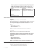
Command Function H1 Force modem off-hook (make busy) Note: H1 command is not supported for Italy I_ L_ M_ I0 Display product-identification code I1 Factory ROM checksum test I2 Internal memory test I3 Firmware ID I4 Reserved ID L0 Low speaker volume L1 Low speaker volume L2 Medium speaker volume L3 High speaker volume M0 Internal speaker off M1 Internal speaker on until carrier detected M2 Internal speaker always on M3 Internal speaker on until carrier detected and off while d
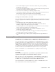
Extended AT commands Command Function &C0 Force Carrier Detect Signal High (ON) &C1 Turn on CD when remote carrier is present &D0 Modem ignores the DTR signal &D1 Modem returns to Command Mode after DTR toggle &D2 Modem hangs up, returns to the Command Mode after DTR toggle &D3 Resets modem after DTR toggle &F_ &F Recall factory default configuration &G_ &G0 Guard tone disabled &G1 Guard tone disabled &G2 1800 Hz guard tone &K0 Disable flow control &K3 Enable RTS/CTS hardware flow
Command Function &W_ %E_ &V1 Display Last Connection Statistics &W0 Stores the active profile as Profile 0 &W1 Stores the active profile as Profile 1 %E0 Disable auto-retrain %E1 Enable auto-retrain +MS? Displays the current Select Modulation settings +MS=? Displays a list of supported Select Modulation options +MS=a,b,c,e,f Select modulation where: a=0, 1, 2, 3, 9, 10, 11, 12, 56, 64, 69; b=0-1; c=300-56000; d=30056000; e=0-1; and f=0-1. A, b, c, d, e, f default=12, 1, 300, 56000, 0, 0.
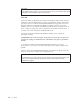
Fax Class 1 commands +FAE=n Data/Fax Auto Answer +FCLASS=n Service Class +FRH=n Receive data with HDLC framing +FRM=n Receive data +FRS=n Receive silence +FTH=n Transmit data with HDLC framing +FTM=n Transmit data +FTS=n Stop transmission and wait Fax Class 2 commands +FCLASS=n Services class. +FAA=n Adaptive answer. +FAXERR Fax error value. +FBOR Phase C data bit order. +FBUF? Buffer size (read only). +FCFR Indicate confirmation to receive. +FCLASS= Service class.
+FPHCTO Phase C time out. +FPOLL Indicates polling request. +FPTS: Page transfer status. +FPTS= Page transfer status. +FREV? Identify revision. +FSPT Enable polling. +FTSI: Report the transmit station ID.
Attention Switzerland User: If your Swisscom phone line does not have Taxsignal switched OFF, modem function may be impaired. The impairment may be resolved by a filter with the following specifications: Telekom PTT SCR-BE Taximpulssperrfilter-12kHz PTT Art. 444.112.7 Bakom 93.0291.Z.N Appendix B.
34 User Guide
Appendix C. Notices IBM may not offer the products, services, or features discussed in this document in all countries. Consult your local IBM representative for information on the products and services currently available in your area. Any reference to an IBM product, program, or service is not intended to state or imply that only that IBM product, program, or service may be used.
Intel, Celeron, NetBurst, and Pentium are trademarks of Intel Corporation in the United States, other countries, or both. Microsoft, Windows, and Windows NT are trademarks of Microsoft Corporation in the United States, other countries, or both. Other company, product, and service names may be trademarks or service marks of others.
Index A F Access IBM ix adapter installing 14 peripheral component interconnect (PCI) slots 14 audio subsystem 2 features 1 B battery 17 BIOS settings 21 C cable lock 17 cables, connecting 19 changing the battery 17 commands Basic AT 27 Extended AT 29 Fax Class 1 31 Fax Class 2 31 MNP/V.42/V.42bis/V.
R recovering from a POST/BIOS update failure 26 removing drives 11 removing the cover 9 replacing the cover 19 riser card 14 S safety information v security cable lock 17 features 3 profile by device 23 software 3 specifications 5 startup sequence 23 system board components, accessing 11 connectors 12 identifying parts 12 location 12 memory 4, 13 system management 2 T tools 6 U updating POST/BIOS 25 using IBM Setup Utility 21 passwords 22 security profile by device 23 V video subsystem 2 38 User Guide
Part Number: 59P7543 Printed in U.S.A.