IBM Hardware Maintenance Manual Types 6826, 8317, 8318, and 8319
IBM Hardware Maintenance Manual Types 6826, 8317, 8318, and 8319
Note: Before using this information and the product it supports, be sure to read the general information under “Notices” on page 143. Second Edition (December 2002) INTERNATIONAL BUSINESS MACHINES CORPORATION PROVIDES THIS PUBLICATION ″AS IS″ WITHOUT ANY WARRANTY OF ANY KIND, EITHER EXPRESS OR IMPLIED, INCLUDING, BUT NOT LIMITED TO, THE LIMITED WARRANTIES OF MERCHANTABILITY OR FITNESS FOR A PARTICULAR PURPOSE.
Contents Chapter 1. About this manual . . . . . 1 Important Safety Information . . . . . . . . Power supply . . . . . . . . . . . . . 34 . 1 Chapter 7. Symptom-to-FRU Index . . . 37 Chapter 2. General Checkout. . . . . . 3 Chapter 3. General information . . . . . 5 Features . . . . Specifications . . Available options . . . . . . . . . . . . . . . . . . . . . . . . . . . . . . . . . . . 5 . 7 . 8 Chapter 4. Diagnostics . . . . . . . . 9 IBM Setup Utility program . . . . .
iv Hardware Maintenance Manual
Chapter 1. About this manual ® This manual contains service and reference information for IBM computer Types 6826, 8317, 8318, and 8319. This manual is divided into product service sections and a related service section, as follows: v The product service sections include procedures for isolating problems to a FRU, a Symptom-to-FRU Index, additional service information and an illustrated parts catalog.
Leia todas as instruções de cuidado e perigo antes de executar qualquer operação. Lea atentamente todas las declaraciones de precaución y peligro ante de llevar a cabo cualquier operación.
Chapter 2. General Checkout This general checkout procedure is for Type 6826, 8317, 8318, and 8319 computers. Attention: The drives in the computer you are servicing might have been rearranged or the drive startup sequence changed. Be extremely careful during write operations such as copying, saving or formatting. Data or programs can be overwritten if you select an incorrect drive. Diagnostic error messages appear when a test program finds a problem with a hardware option.
If NO, continue to 002 . If YES, proceed to 003 . 002 If the Power Management feature is enabled, do the following: 1. Start the Configuration/Setup Utility program (see “IBM Setup Utility program” on page 9) 2. Select Power Management from the Configuration/Setup Utility program menu. 3. Select APM. 4. Be sure APM BIOS Mode is set to Disabled. If it is not, press Left Arrow (}) or Right Arrow (Æ) to change the setting. 5. Select Automatic Hardware Power Management. 6.
Chapter 3. General information This IBM® computer incorporates many of the latest advances in computer technology and can be upgraded as needs change. Adding hardware options to a computer is an easy way to increase its capabilities. Instructions for installing external and internal options are included in this publication. When adding an option, use these instructions along with the instructions that come with the option.
v v v v Remote Administration Automatic power-on startup System Management (SM) BIOS and SM software Ability to store POST hardware test results Input/output features v 25-pin, Extended Capabilities Port (ECP)/Extended Parallel Port (EPP) v Two 9-pin serial connectors v Six 4-pin, USB connectors (four on front panel and two on rear panel) v PS/2® mouse connector v PS/2 keyboard connector v Ethernet connector v VGA Monitor connector v Three audio connectors (line in, line out, and microphone) on rear panel
Specifications This section lists the specifications for the computer. Dimensions Width: 12.2 inches (309 mm) Heat output (approximate) in British thermal units (Btu) per hour: Height: 3.3 inches (84 mm) Minimum configuration: 257 Btu/hr (75 watts) Depth: 13.6 inches (345 mm) Maximum configuration: 463 Btu/hr (135 watts) Airflow Weight Minimum configuration as shipped: 7.4 kg (16.
Available options The following are some available options: v External options – Parallel port devices, such as printers and external drives – Serial port devices, such as external modems and digital cameras – Audio devices, such as external speakers for the sound system – USB devices, such as printers, joysticks, and scanners – Security device, such as a cable lock – Monitors v Internal options – System memory, called dual inline memory modules (DIMMs) – Peripheral component interconnect (PCI) adapters – C
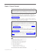
Chapter 4. Diagnostics The following tools are available to help identify and resolve hardware-related problems. v Setup Utility program v Power-On Self-Test (POST) – POST Beep Codes – Error Code Format v Diagnostics program v Recovery utility – Factory Contents – Partial recovery v Repair utility IBM Setup Utility program The IBM Setup Utility program is stored in the electrically erasable programmable read-only memory (EEPROM) of your computer.
of the first IBM Setup Utility screen is shown here. 831941x 28KT10AUS 2810A IBM 1234567 02/22/02 [13:34:25] [02/22/2002] The IBM Setup Utility program menu lists items that identify system configuration topics. When working with the IBM Setup Utility program menu, you must use the keyboard. The keys used to perform various tasks are displayed at the bottom of each screen.
Product Recovery Program menu Type 6826, 8317, 8318, and 8319 machines have recovery and diagnostics programs on a separate hard drive partition. The Enhanced Diagnostics diskette is not shipped with the machine. To download the Diagnostics program, see “Diagnostics program download” on page 12. At startup, the machine displays the following prompt: To start the Product Recovery Program, press F11 Attention: Make sure all data is backed up to avoid loss when the Product Recovery program is used.
Diagnostics The Diagnostics program uses a full range of diagnostic utilities to determine the operating condition of the computer’s hardware components. For a complete list of error codes and messages, see ″Symptom-to-FRU Index″ on page 37. Diagnostics program download To download the Diagnostics program, do the following: v Go to http://www.pc.ibm.com/support/us/. v Search for the machine Type and model in the ″Quick path to a product″ box on the left.
Test results Diagnostics test results will produce the following error code format: Function Code Failure Type DeviceID Date ChkDigits Text v Function Code: Represents the feature or function within the PC. v Failure Type: Represents the type of error encountered. v DeviceID: Contains the component’s unit-ID which corresponds to either a fixed disk drive, removable media drive, serial or parallel port, processor, specific RIMM, or a device on the PCI bus.
– Random Verify v Surface Scan Tests: - checks the drive media for defects. – Surface Scan (Linear) – Surface Scan (Aggressive) - this is disabled for normal customer use. – Surface Scan (Random) v SMART: - checks the SMART functionality for drives that support SMART. – Start SMART Self-Test – Get SMART test results Other Test Features: v Write-Splice Repair - detects and corrects Error Correction Code errors during Verify tests.
Quick and Full erase - hard drive The Diagnostics program offers two hard drive format utilities: v Quick Erase Hard Drive v Full Erase Hard Drive The Quick Erase Hard Drive provides a DOS utility that performs the following steps. v Destroys the Master Boot Record (MBR) on the hard drive. v Destroys all copies of the FAT Table on all partitions (both the master and backup). v Destroys the partition table. v Provides messages that warn the user that this is a non-recoverable process. Chapter 4.
The Full Erase Hard Drive provides a DOS utility that performs the following steps. v Performs all the steps in Quick Erase. v Provides a DOS utility that writes random data to all sectors of the hard drive. v Provide an estimate of time to completion along with a visual representation of completion status. v Provides messages that warn the user about non-recoverable process. Important: Make sure that all data is backed up before using the Quick or Full Erase functions.
Chapter 5. Installing Options This section contains information on adding or replacing customer options. Installing external options This section shows the various external connectors on the computer to which external options may be attached. When adding an external option, use the information in this section to identify the required connector, and then use the instructions that come with the option to make the connection and install any software or device drivers that are required for the option.
Locating connectors on the rear of the computer The following illustration shows locations of connectors on the rear of the computer.
Removing the cover To remove the cover: 1. Shut down the operating system, remove any media (diskettes, CDs, or tapes) from the drives, and turn off all attached devices and the computer. 2. Unplug all power cords from electrical outlets. 3. Disconnect all cables attached to the computer. This includes power cords, input/output (I/O) cables, and any other cables that are connected to the computer. 4. Remove the floor stand, if attached. 5. Remove the padlock or cable lock if installed. 6.
Removing the bezel To remove the bezel: 1. Remove the cover. See “Removing the cover” on page 19. 2. Lift the three tabs holding the bezel in place and pull forward and off.
Locating components The following illustration will help you locate the various components in the computer. 1 2 3 4 5 Diskette drive System board DIMM connectors PCI riser Power supply 6 7 8 9 Hard disk drive CD or DVD drive Battery Disk drive tray Chapter 5.
Accessing system board components and drives To access some components on the system board such as memory, the battery, and the Clear CMOS/BIOS recovery jumper, it may be necessary to slide the diskette and CD drive tray outward to the front of the computer. To 1. 2. 3. access system board components or drives: Turn off the computer. Remove the cover. See “Removing the cover” on page 19. Remove the screw securing the drive tray to the riser card support. 4.
Identifying parts on the system board The system board (sometimes called the planar or motherboard) is the main circuit board in the computer. It provides basic computer functions and supports a variety of devices that are IBM-installed or that can be installed later. The following illustration shows the locations of parts on the system board.
Installing memory Type 6826, 8317, 8318, and 8319 computers have two connectors for installing dual inline memory modules (DIMMs) that provide up to a maximum of 2 GB of system memory. When installing memory, the following rules apply: v Use 2.5 V, 184-pin, double data rate synchronous dynamic random access memory (DDR SDRAM), non-ECC DIMMs. v Use 128 MB, 256 MB, 512 MB, or 1 GB DIMMs in any combination. Note: Only DDR SDRAM DIMMs can be used. To install DIMMs: 1. Access the system board.
7. Replace the cover. See “Replacing the cover and connecting the cables” on page 30. Installing PCI adapters This section provides information and instructions for installing and removing PCI adapters. The computer has a riser card with two PCI expansion slots. To install a PCI adapter: 1. Remove the cover. See “Removing the cover” on page 19. 2. Remove the PCI riser and adapters that are already installed. 3. Remove the adapter-slot-cover latch and the slot cover for the appropriate expansion slot. 4.
Installing a drive in the disk drive tray This section provides information and instructions for installing and removing internal drives. Drives that are available for Type 6826, 8317, 8318, and 8319 computers are: v Hard disk drives v Tape drives v CD drives or DVD drives v Diskette and other removable media drives When installing an internal drive, it is important to note what type and size of drive that you can install in each bay.
5. Reinstall the disk drive tray. Go to “Connecting a diskette drive” on page 28 or “Connecting an IDE CD drive”. Note: Be sure to connect the system fan cable before sliding the disk drive tray back in. 6. Replace the bezel and cover. Replacing the hard disk drive To replace the hard disk drive, follow these steps. 1. Remove the cover. See “Removing the cover” on page 19. 2. Remove the disk drive tray. See “Accessing system board components and drives” on page 22. 3.
What to do next: v To work with another option, go to the appropriate section. v To complete the installation, go to “Replacing the cover and connecting the cables” on page 30. Connecting a diskette drive 1. Locate the cable that came with your computer or with the new drive. 2. Locate the diskette drive connector on the system board. See “Identifying parts on the system board” on page 23. 3. Connect one end of the signal cable to the drive and the other to the diskette drive connector on the system board.
See the following illustration for cable lock installation. ® Changing the battery Type 6826, 8317, 8318, 8319 computers have a special type of memory that maintains the date, time, and settings for built-in features, such as parallel-port assignments (configuration). A battery keeps this information active when the computer is turned off. The battery normally requires no charging or maintenance throughout its life; however, no battery lasts forever.
4. Install the new battery. 5. Reconnect any cables that were disconnected. Slide the drive tray back into the computer, making sure both side tabs lock. 6. Install the PCI riser and adapters if removed. 7. Replace the cover, and connect the cables. See “Replacing the cover and connecting the cables”. Note: When the computer is turned on for the first time after battery replacement, an error message might be displayed. This is normal after replacing the battery. 8.
1. Ensure that all components have been reassembled correctly and that no tools or loose screws are left inside your computer. 2. Clear any cables that might impede the replacement of the cover. 3. Place the cover over the computer and slide it to the rear until it is fully closed. Secure the cover with the two thumbscrews. 4. If your computer is being placed in the vertical position, attach the floor stand.
32 Hardware Maintenance Manual
Chapter 6. FRU Removals These removals are to be done by trained service technicians only. Important: Before you install or remove any option, read “Safety information” on page 109. These precautions and guidelines will help you work safely. Removing the retention bar and PCI riser card To remove the retention bar and riser card, do the following: 1. Turn off the computer and peripheral devices and disconnect all external cables and power cords; then, remove the cover. See “Removing the cover” on page 19.
4. Unscrew the fansink from the system board and carefully lift it off. The processor will come with it, attached to the bottom by thermal grease. 5. To remove the fansink from the processor, remove the assembly from the system board, and twist the processor to break the seal formed by the thermal grease and remove. System board To remove the system board, do the following: 1. Turn off the computer and peripheral devices and disconnect all external cables and power cords; then, remove the cover.
2. Remove the drive tray. See “Installing a drive in the disk drive tray” on page 26. 3. Remove the hard disk drive. See “Replacing the hard disk drive” on page 27. 4. Disconnect all power supply wires. 5. Remove the system board. See“System board” on page 34. 6. Remove the screws holding the power supply. 7. Lift out the power supply. Chapter 6.
36 Hardware Maintenance Manual
Chapter 7. Symptom-to-FRU Index The Symptom-to-FRU index lists error symptoms and possible causes. The most likely cause is listed first. Always begin with ″General Checkout″ on page 3. This index can also be used to help you decide which FRUs to have available when servicing a computer. If you are unable to correct the problem using this index, go to “Undetermined problems” on page 77. Notes: v If you have both an error message and an incorrect audio response, diagnose the error message first.
38 Check/Verify FRU/Action Check the power-on switch for continuity.
Diagnostic error codes Refer to the following diagnostic error codes when using the diagnostic tests. See ″Diagnostics″ on page 9 for the specific type for information about the Diagnostic programs. In the following index, X can represent any number. Diagnostic Error Code FRU/Action 000-000-XXX BIOS Test Passed 1. No action 000-002-XXX BIOS Timeout 1. Flash the system 000-024-XXX BIOS Addressing test failure 1. Flash the system 000-025-XXX BIOS Checksum Value error 1. Flash the system 2.
Diagnostic Error Code FRU/Action 000-197-XXX BIOS test warning 1. Make sure the component that is called out is connected and/or enabled 2. Re-run test 3. Component that is called out in warning statement 4. Component under test 000-198-XXX BIOS test aborted 1. If a component is called out, make sure it is connected and/or enabled 2. Flash the system and re-test 3. Go to the ″Undetermined problems″ section 000-199-XXX BIOS test failed, cause unknown 1. Go to the ″Undetermined problems″ section 2.
Diagnostic Error Code FRU/Action 001-038-XXX System Extension failure 1. Adapter card 001-039-XXX System DMI data structure error 1. Flash the system 001-040-XXX System IRQ failure 1. Power-off/on system and re-test 001-041-XXX System DMA failure 1. Power-off/on system and re-test 001-195-XXX System Test aborted by user 1. Information 001-196-XXX System test halt, error threshold exceeded 1. Press F3 to review the log file 001-197-XXX System test warning 1.
42 Diagnostic Error Code FRU/Action 001-271-XXX System IRQ4 failure 1. Device on IRQ4 001-272-XXX System IRQ5 failure 1. Device on IRQ5 001-273-XXX System IRQ6 (diskette drive) failure 1. Diskette Cable 001-274-XXX System IRQ7 failure 1. Device on IRQ7 001-275-XXX System IRQ8 failure 1. Device on IRQ8 001-276-XXX System IRQ9 failure 1. Device on IRQ9 001-277-XXX System IRQ10 failure 1. Device on IRQ10 001-278-XXX System IRQ11 failure 1. Device on IRQ11 001-279-XXX System IRQ12 failure 1.
Diagnostic Error Code FRU/Action 001-301-XXX System RTC Century byte error 1. Flash the system 005-000-XXX Video Test Passed 1. No action 005-00X-XXX Video error 1. Video card, if installed 005-010-XXX 005-011-XXX 005-012-XXX 005-013-XXX Video Signal failure 1. Video card, if installed 005-016-XXX Video Simple Pattern test failure 1. Video Ram 005-024-XXX Video Addressing test failure 1. Video card, if installed 005-025-XXX Video Checksum Value error 1.
Diagnostic Error Code FRU/Action 005-197-XXX Video test warning 1. Make sure the component that is called out is connected and/or enabled 2. Re-run test 3. Component that is called out in warning statement 4. Component under test 005-198-XXX Video test aborted 1. If a component is called out, make sure it is connected and/or enabled 2. Flash the system and re-test 3. Go to the ″Undetermined problems″ section 005-199-XXX Video test failed, cause unknown 1. Go to the ″Undetermined problems″ section 2.
Diagnostic Error Code FRU/Action 011-000-XXX Serial port Interface Test Passed 1. No action 011-001-XXX Serial port Presence 1. Remove external serial device, if present 2. Run setup, enable port 3. System board 011-002-XXX 011-003-XXX Serial port Timeout/Parity error 1. System board 011-013-XXX 011-014-XXX Serial port Control Signal/Loopback test failure 1. System board 011-015-XXX Serial port External Loopback failure 1.
Diagnostic Error Code FRU/Action 014-000-XXX Parallel port Interface Test Passed 1. No action 014-001-XXX Parallel port Presence 1. Remove external parallel device, if present 2. Run setup, enable port 3. System board 014-002-XXX 014-003-XXX Parallel port Timeout/Parity error 1. System board 014-013-XXX 014-014-XXX Parallel port Control Signal/Loopback test failure 1. System board 014-015-XXX Parallel port External Loopback failure 1.
Diagnostic Error Code FRU/Action 015-001-XXX USB port Presence 1. Remove USB device(s) and re-test 015-002-XXX USB port Timeout 1. Remove USB device(s) and re-test 015-015-XXX USB port External Loopback failure 1. Remove USB device(s) and re-test 015-027-XXX USB port Configuration/Setup error 1. Flash the system 015-032-XXX USB port Device Controller failure 1. System board 015-034-XXX USB port buffer allocation failure 1. Reboot the system 2. System board 2. System board 2. System board 2.
Diagnostic Error Code FRU/Action 018-0XX-XXX PCI Card Failure 1. Riser card, if installed 018-195-XXX PCI Card Test aborted by user 1. PCI card 2. System board 2. Information 3. Re-start the test, if necessary 018-196-XXX PCI Card test halt, error threshold exceeded 1. Press F3 to review the log file 018-197-XXX PCI Card test warning 1. Make sure the component that is called out is connected and/or enabled 2. Re-start the test to reset the log file 2. Re-run test 3.
Diagnostic Error Code FRU/Action 020-198-XXX PCI test aborted 1. If a component is called out, make sure it is connected and/or enabled 2. Flash the system and re-test 3. Go to the ″Undetermined problems″ section 020-199-XXX PCI test failed, cause unknown 1. Go to the ″Undetermined problems″ section 2. Flash the system and re-test 3. Replace component under function test 020-262-XXX PCI system error 1. PCI card 2. Riser card, if installed 3. System board 025-000-XXX IDE interface Test Passed 1.
Diagnostic Error Code FRU/Action 025-199-XXX IDE interface test failed, cause unknown 1. Go to the ″Undetermined problems″ section 2. Flash the system and re-test 3. Replace component under function test 030-000-XXX SCSI interface Test Passed 1. No action 030-00X-XXX 030-01X-XXX SCSI interface failure 1. SCSI signal cable 2. Check power supply 3. SCSI device 4. SCSI adapter card, if installed 5. System board 030-027-XXX SCSI interface Configuration/Setup error 1. SCSI signal cable 2.
Diagnostic Error Code FRU/Action 035-0XX-XXX RAID interface Failure 1. RAID signal cable 2. RAID device 3. RAID adapter card, if installed 4. System board 035-195-XXX RAID interface Test aborted by user 1. Information 035-196-XXX RAID interface test halt, error threshold exceeded 1. Press F3 to review the log file 035-197-XXX RAID interface test warning 1. Make sure the component that is called out is connected and/or enabled 2. Re-start the test, if necessary 2.
Diagnostic Error Code FRU/Action 071-197-XXX Audio port test warning 1. Make sure the component that is called out is connected and/or enabled 2. Re-run test 3. Component that is called out in warning statement 4. Component under test 071-198-XXX Audio port test aborted 1. If a component is called out, make sure it is connected and/or enabled 2. Flash the system and re-test 3. Go to the ″Undetermined problems″ section 071-199-XXX Audio port test failed, cause unknown 1.
Diagnostic Error Code FRU/Action 086-032-XXX Mouse Port interface Device controller failure 1. Mouse 086-035-XXX Mouse Port interface Reset 1. Mouse 086-040-XXX Mouse Port interface IRQ failure 1. Run Setup 2. System board 2. System board 2. Mouse 3. System board 086-195-XXX Mouse Port interface Test aborted by user 1. Information 086-196-XXX Mouse Port interface test halt, error threshold exceeded 1. Press F3 to review the log file 086-197-XXX Mouse Port interface test warning 1.
Diagnostic Error Code FRU/Action 089-199-XXX Microprocessor test failed, cause unknown 1. If a component is called out, make sure it is connected and/or enabled 2. Go to the ″Undetermined problems″ section 3. Flash the system and re-test 4. Replace component under function test 170-000-XXX Voltage Sensor(s) Test Passed 1. No action 170-0XX-XXX Voltage Sensor(s) failure 1. Flash system 170-195-XXX Voltage Sensor(s) Test aborted by user 1.
Diagnostic Error Code FRU/Action 175-197-XXX Thermal Sensor(s) test warning 1. Make sure the component that is called out is connected and/or enabled 2. Re-run test 3. Component that is called out in warning statement 4. Component under test 175-198-XXX Thermal Sensor(s) test aborted 1. If a component is called out, make sure it is connected and/or enabled 2. Flash the system and re-test 3. Go to ″Undetermined problems″ section 175-199-XXX Thermal Sensor(s) test failed, cause unknown 1.
Diagnostic Error Code FRU/Action 215-XXX-XXX CD-ROM Drive error 1. CD-ROM Drive Cable 2. Check power supply voltages 3. CD-ROM drive 4. System board 217-000-XXX Hard Disk Drive Test Passed 1. No action 217-25X-XXX 217-26X-XXX Hard Disk Drive (IDE) error 1. Hard Disk Drive Cable 2. Check power supply voltages 3. Hard Disk drive (IDE) 4. System board 217-28X-XXX 217-29X-XXX Hard Disk Drive (SCSI) error 1. Hard Disk Drive Cable 2. Check power supply voltages 3. Hard Disk drive (SCSI) 4.
Beep symptoms Beep symptoms are short tones or a series of short tones separated by pauses (intervals without sound). See the following examples. Beeps Description 1-2-X v One beep v A pause (or break) v Two beeps v A pause (or break) v Any number of breaks 4 Four continuous beeps Use the following table to diagnose beep symptoms. Beep Symptom FRU/Action 1-1-3 CMOS read-write error 1. Run Setup 1-2-2-3 ROM BIOS check error 1. System Board 1-2-1 Programmable Interval Timer failed 1.
Beep Symptom FRU/Action 2-2-4 CMOS configuration info validation failed 1. Battery 2-3-1 Screen initialization failed 1. Jumper on J28 2. System Board 2. System Board 2-3-2 Screen memory failed 1. System Board 2-3-3 Screen retrace failed 1. System Board 1-2 Search for video ROM failed 1. System Board All other beep code sequences 1. System Board Continuous beep 1. System Board Repeating short beeps 1. Keyboard stuck key 2. Keyboard Cable 3.
No-beep symptoms Symptom/Error FRU/Action No beep during POST but computer works correctly. 1. System Board No beep during POST. 1. See “Undetermined problems” on page 77. 2. System Board 3. Memory Module 4. Any Adapter or Device 5. Riser Card 6. Power Cord 7. Power Supply Chapter 7.
POST error codes Each time you power-on the system, it performs a series of tests that check the operation of the system and some options. This series of tests is called the Power-On Self-Test, or POST. POST does the following operations.
POST Error Code FRU/Action 111 I/O channel parity error 1. Reseat adapters 2. Any adapter 3. Riser card 4. System Board 114 Adapter ROM error 1. Adapter Memory 2. System Board 3. Riser card 129 Internal cache test error 1. Processor 2. L2 Cache Memory 3. System Board 135 Fan failure 1. Fan 2. System board 151 System board failure 1. System Board 161 Bad CMOS battery 1. Run Setup 2. CMOS Backup Battery (see “Safety information” on page 109) 3. System Board 162 Configuration mismatch 1.
POST Error Code FRU/Action 168 Alert on LAN error 1. Run Setup. Check to see that Ethernet and Alert on LAN are enabled. 2. System Board 17X, 18X 1. C2 Security 175 Primary Copy of Secure Data is damaged 1. Run Configuration. See “IBM Setup Utility program” on page 9. 2. System Board 176 The System has been tampered with 1. Covers were removed from the computer 177 Corrupted Administrator Password 1. System Board 178 1. System Board 179 Boot Integrity Services Segment Error 1.
POST Error Code FRU/Action 303 With an 8603 error 1. Mouse 2. Keyboard 3. Keyboard Cable 4. System Board 303 With no 8603 error 1. Keyboard 2. Keyboard Cable 3. System Board 3XX Not listed above 1. Keyboard 2. Keyboard Cable 3. System Board 5XX 1. Video Adapter (if installed) 2. System Board 601 1. Diskette Drive A 2. Diskette Drive Cable 3. System Board 4. Riser card 602 1. Bad Diskette? 2. Verify Diskette and retry 604 And able to run diagnostics 1.
POST Error Code FRU/Action 962 Parallel port configuration error 1. Run Configuration 2. Parallel Adapter (if installed) 3. System Board 9XX 1. Printer 2. System Board 1047 1. 16-Bit AT™ Fast SCSI Adapter 107X Check SCSI terminator installation 1. Check SCSI terminator installation 2. SCSI Cable 3. SCSI Terminator 4. SCSI Device 5. SCSI Adapter 1101 1. Run Enhanced Diagnostics Serial connector error, possible system board failure 1101, 1102, 1106, 1108, 1109 1. System Board 2.
POST Error Code FRU/Action 1207 1. Communications Cable 2. Dual Async Adapter/A 13XX 1. Game Adapter 1402 Printer not ready Information only 1403 No paper error, or interrupt failure Information only 1404 System board timeout failure 1. Run Enhanced Diagnostics 1405 Parallel adapter error 1. Run Enhanced Diagnostics 1406 Presence test error 1. Run Enhanced Diagnostics 14XX Not listed above. Check printer before replacing system board 1. Printer 15XX 1.
POST Error Code FRU/Action 1802 PCI/PnP Error! Not Enough I/O Space 1. Run Setup and verify PCI/ISA Available configuration settings. 2. If necessary, set ISA adapters to Not available to allow PCI adapters to properly configure. 3. Remove any suspect ISA adapters. 4. Rerun diagnostics. 5. PCI Adapter 1803 PCI/PnP Error! Not Enough Memory Space Available 1. Run Setup and verify PCI/ISA configuration settings. 2. If necessary, set ISA adapters to Not available to allow PCI adapters to properly configure.
POST Error Code FRU/Action 21XX 1. SCSI Device 2. 16-bit AT Fast SCSU adapter 3. Alternate BSC adapter 2401, 2402 If screen colors change 1. Display 2401, 2402 If screen colors are OK 1. System Board 2409 1. Display 2410 1. System Board 2. Display 2. Display 2462 Video memory configuration error 1. Check cable connections 2. Run Setup and verify video configuration settings 3. Video Memory Modules 4. Video Adapter (if installed) 5. System Board 4611, 4630 1. Multiport/2 Interface Board 2.
POST Error Code FRU/Action 78XX 1. High Speed Adapter 79XX 1. 3117 Adapter 80XX 1. PCMCIA Adapter 84XX 1. Speech Adapter 2. Speech Control Assembly. 8601, 8602 1. Pointing Device (Mouse) 2. System Board 8603, 8604 Pointing Device Error 1. System Board 2. Pointing Device (Mouse) 86XX Not listed above 1. Mouse 89XX 1. PC Music Adapter 2. System Board 2. MIDI Adapter Unit 91XX 1. Optical Drive 2. Adapter 96XX 1. SCSI Adapter 2. Any SCSI Device 3. System Board 4.
POST Error Code FRU/Action 10132, 10135, 10138, 10141, 10144, 10147, 10150, 1. Modem 10133, 10136, 10139, 10142, 10145, 10148, 10151, 10134, 10137, 10140, 10143, 10146, 10149, 10152 10153 1. Data/Fax Modem 2. System Board 3. Riser card 101XX Not listed above 1. Modem Adapter/A 2. Data/Fax Modem 3. System Board 4. Riser card 10450, 10451, 10490, 10491, 10492, 10499 Read/write error 1. Run Enhanced Diagnostics 2. Hard Disk Drive 3. System Board 4. Riser card 10452 Seek test error 1.
POST Error Code FRU/Action 10480 1. Hard Disk Drive (ESDI) 2. Drive Cable 3. System Board 10481 ESDI drive D seek error 1. Run Enhanced Diagnostics 10482 Drive select acknowledgement bad 1. Run Enhanced Diagnostics 106X1 1. Check Configuration 2. Ethernet Adapter 10635 1. Power-off computer, wait ten seconds then power-on the computer 2. Ethernet Adapter 10651, 10660 1. Check Cables 2. Ethernet Adapter 106XX Not listed above 1. Ethernet Adapter 107XX 1. 5.25-inch External Diskette Drive 2.
POST Error Code FRU/Action 143XX 1. Japanese Display Adapter 2. System Board 3. Riser card 14710, 14711 1. System Board Video Adapter 2. Adapter Video Memory 148XX 1. Video Adapter 14901, 14902, 1491X, 14922 1. Video Adapter (if installed) 2. System Board 3. Riser card 4. Display (any type) 14932 1. External Display 2. Video Adapter 161XX 1. FaxConcentrator Adapter 164XX 1. 120 MB Internal Tape Drive 2. Diskette Cable 3. System Board 4. Riser card 16500 1. 6157 Tape Attachment 2.
POST Error Code FRU/Action 200XX Not listed above 1. Image Adapter/A 2. Image-I Adapter/A 3. Memory Module DRAM, VRAM 4. System Board 5. Riser card 20101 to 20103 1. Printer/Scanner Option 2. Image Adapter/A 3. Memory Module DRAM, VRAM 20104 1. Memory Module DRAM, VRAM 2. Printer/Scanner Option 3. Image Adapter/A 20105 to 20110 1. Printer/Scanner Option 2. Image Adapter/A 3. Memory Module DRAM, VRAM Image Adapter/A Memory Test failure indicated by graphic of adapter 1.
POST Error Code FRU/Action 212XX 1. SCSI Printer 2. Printer Cable 213XX 1. SCSI Processor 214XX 1. WORM Drive 215XXXC, 215XXXD, 215XXXE, 215XXXU If an external device, and power-on LED is off, check external voltages 1. CD-ROM Drive I 2. CD-ROM Drive II Enhanced CD-ROM Drive II Any CD-ROM Drive 3. SCSI Cable 4. SCSI Adapter or System Board 216XX 1. Scanner 217XX If an external device, and power-on LED is off, check external voltages 1.
POST Error Code FRU/Action 27558, 27559, 27560, 27561 1. PCMCIA Type II Modem 2. ServerGuard Adapter 27562 1. External Power Control not connected 2. External Power Control 3. ServerGuard Adapter 27563, 27564 1. External Power Control 2. ServerGuard Adapter 275XX 1. Update Diagnostic Software 27801 to 27879 1. Personal Dictation System 2. Adapter 3. System Board 74 27880 to 27889 1. External FRU (Speaker, Microphone) 999030X Hard disk reset failure 1.
Miscellaneous error messages Message/Symptom FRU/Action CMOS Backup Battery inaccurate 1. CMOS Backup Battery (see “Safety information” on page 109) 2. System Board Changing colors 1. Display Computer will not power-off. See “Power Supply Errors” on page 37. 1. Power Switch 2. System Board 3. Riser card Computer will not RPL from server 1. Ensure that network is in startup sequence as first device or first device after diskette 2. Ensure that network adapter is enabled for RPL 3.
Message/Symptom ″Insert a Diskette″ icon appears with a known-good diagnostics diskette in the first 3.5-inch diskette drive. FRU/Action 1. System Board 2. Diskette Drive Cable 3. Riser card 4. Network Adapter Intensity or color varies from left to right of characters and color bars 1. Display No power or fan not running 1. See “Power Supply Errors” on page 37. Non-system disk or disk error-type message with a known-good diagnostic diskette. 1. Diskette Drive 2. System Board 2. System Board 3.
Undetermined problems Check the power supply voltages (see “Power Supply Errors” on page 37). If the voltages are correct, return here and continue with the following steps. 1. Power-off the computer. 2. Remove or disconnect the following components (if installed) one at a time. a. Non-IBM devices b. External devices (modem, printer, or mouse) c. Any adapters d. Riser card e. Memory modules f. Extended video memory g. External Cache h. External Cache RAM i. Hard disk drive j. Diskette drive 3.
78 Hardware Maintenance Manual
Chapter 8. Parts listing This section lists the replaceable FRUs for Machine Types 6826, 8317, 8318, and 8319. 1 12 11 2 10 3 9 4 8 5 6 7 Item # © Copyright IBM Corp.
Item # 80 Machine Type 6826 FRU# CRU? 3 CD-ROM Drive 48X - Black (models 11M 11J 12J 13J 14J 22M 31M 31J 32J 33J 34M 34J 39B 41M 42M 41J 42J 23J 24J 25J 26M A1E A1J A2J A3J A4J A5M 51J 52J 53J 54J 55M 43J 44J 45B 46M 61M 22E 22J) 33P3211 Y 3 CD-ROM Drive 48X - Black (models 11M 11J 12J 13J 14J 22M 31M 31J 32J 33J 34M 34J 39B 41M 42M 41J 42J 23J 24J 25J 26M A1E A1J A2J A3J A4J A5M 51J 52J 53J 54J 55M 43J 44J 45B 46M 61M 22E 22J) 33P3215 Y 3 DVD-ROM 16X/48X - Black 33P3259 Y 3 DVD-ROM 16X/48
Item # Machine Type 6826 FRU# CRU? 10 Planar w/10/100 E-net (models 11M 11J 12J 13J 14J 15J 16J 22M 31M 31J 32J 33J 34M 34J 35J 36J 37J 38J 39B 17J 41M 42M CAJ CBJ CCJ CDJ CEJ CFJ CGJ 41J 42J 23J 24J 25J 26M 27J 28J 29J 2AJ 2BJ A1E A1J A2J A3J A4J A5M A6J A7J A8J A9J AAJ 51J 52J 53J 54J 55M 56E 56J 57J 58J 59J 43J 44J 45B 46M 47E 47J 48J 49J 4AJ 61M CHJ CJJ CKJ CLJ 22E 22J) 03R0329 N 10 Planar, w/gigabit E-net 03R0331 N 11 Processor P4 1.
Item # Machine Type 6826 FRU# CRU? Speaker Power brick - US, CE, CF, LA, Taiwan 10K2587 Y Speaker Power brick - Japan (models 16J 2BJ AAJ) 10K2593 Y System fan (all models) 49P3694 Y System screw kit (all models) 49P3696 Y Vertical stand (all models) 49P3701 Y Recovery CDs Win2K FRU# CRU? US/UK/AP/TH Win2000 Recovery CD (models 34M 42M) 71P6405 Y FR/CF Win2000 Recovery CD 71P6425 Y GR Win2000 Recovery CD 71P6413 Y IT Win2000 Recovery CD 71P6433 Y BR Win2000 Recovery CD 71P
Recovery CDs Win XP- Home FRU# CRU? DK Win XP-Home Recovery CD 71P6577 Y NL Win XP-Home Recovery CD 71P6601 Y AE Win XP-Home Recovery CD 71P6625 Y SV Win XP-Home Recovery CD 71P6569 Y HE Win XP-Home Recovery CD 71P6613 Y FI Win XP-Home Recovery CD 71P6589 Y NO Win XP-Home Recovery CD 71P6597 Y PL Win XP-Home Recovery CD 71P6617 Y PO Win XP-Home Recovery CD 71P6609 Y RU Win XP-Home Recovery CD 71P6637 Y HU Win XP-Home Recovery CD 71P6633 Y CZ Win XP-Home Recovery CD 71P66
Recovery CDs Win XP- Pro 84 Hardware Maintenance Manual FRU# CRU? CZ Win XP-Pro Recovery CD 71P6541 Y TR Win XP-Pro Recovery CD 71P6549 Y GK Win XP-Pro Recovery CD 71P6561 Y Japanese Win XP-Pro Recovery CD (models 11J 31J 35J 17J 41J 27J A1J A6J 51J 56J 47J 22J) 71P5958 Y Simplified Chinese Win XP-Pro Recovery CD 71P6093 Y Taiwan TC Win Xp-Pro Recovery CD 71P6096 Y Hong Kong TC Win XP-Pro Recovery CD 71P6099 Y Keyboards (Standard PS/2 Black) FRU# CRU? US English (models 11M 22M
Keyboards (Standard PS/2 Black) FRU# CRU? Serbian/Cyrillic 32P5127 Y Slovak 32P5128 Y Spanish 32P5129 Y Swedish/Finn 32P5130 Y Swiss F/G 32P5131 Y Thailand 32P5132 Y Turkish 32P5133 Y Turkish 32P5134 Y UK English 32P5135 Y US International 32P5136 Y Yugoslav/Latin 32P5137 Y Brazil/Portuguese 32P5138 Y Keyboards RAK III Lite FRU# CRU? US English 19K1910 Y Arabic 19K1911 Y Belgian/French 19K1912 Y Belgian/UK 19K1913 Y Brazil/Portuguese 19K1948 Y Bulgari
Keyboards RAK III Lite Item # 86 FRU# CRU? Serbian/Cyrillic 19K1937 Y Slovak 19K1938 Y Spanish 19K1939 Y Swedish/Finn 19K1940 Y Swiss F/G 19K1941 Y Thailand 19K1942 Y Turkish 19K1943 Y Turkish 19K1944 Y UK English 19K1945 Y US International 19K1946 Y Yugoslav/Latin 19K1947 Y Japanese 19K1908 Y Power Cords FRU# CRU? Line Cord (models 11M 22M 31M 34M 41M 42M 26M A5M 55M 46M 61M) 6952301 Y Line Cord 13F9939 Y Line Cord 13F9978 Y Line Cord 14F0032 Y Line C
Item # Machine Type 8317 FRU# CRU? 3 DVD-ROM 16X/48X - Black 33P3259 Y 3 DVD-ROM 16X/48X - Black 33P3281 Y 3 DVD-ROM 16X/48X - Black 33P3277 Y 3 40X12X40X CD-RW - Black 33P3269 Y 3 40X12X40X CD-RW - Black 33P3273 Y 3 48X24X48X CD-RW - Black 33P3293 Y 3 48X24X48X CD-RW - Black 33P3289 Y 4 FDD 3.5″ 1.44 MB (model 22G 23U 23S 23P 23Y 71G 31U 31S 31P 31Y 32G) 76H4091 Y 4 FDD 3.5″ 1.
Item # 88 Hardware Maintenance Manual Machine Type 8317 FRU# CRU? Feet (all models) 49P3702 Y Cable, HDD, ATA100 (all models) 49P3703 Y Cable, CD-ROM (all models) 49P3704 Y Cable, FDD (all models) 49P3705 Y Cable, serial assembly (all models) 49P3707 Y Cable, power/LED (all models) 49P3708 Y Mouse, PS/2 2-button (black) (models 22G 23U 23S 23P 23Y 24U 24S 24P 24Y 71G 31U 31S 31P 31Y 32G) 24P0383 Y Mouse, scrollpoint III (black) 24P0485 Y Recovery CDs Win XP- Pro FRU# CRU? US
Keyboards (PS/2 Fullwidth ID Black) FRU# CRU? Belgian/French (model 22G 71G 32G) 32P5102 Y Belgian/UK (model 22G 71G 32G) 32P5103 Y Bulgarian (model 22G 71G 32G) 32P5104 Y Chinese/US 32P5105 Y Czech (model 22G 71G 32G) 32P5106 Y Danish (model 22G 71G 32G) 32P5107 Y Dutch (model 22G 71G 32G) 32P5108 Y French (model 22G 71G 32G) 32P5109 Y French Canadian 32P5110 Y French Canadian 32P5111 Y German (model 22G 71G 32G) 32P5112 Y Greek (model 22G 71G 32G) 32P5113 Y Hebrew (m
Power Cords Item # 90 FRU# CRU? Line Cord 13F9939 Y Line Cord (model 22G 71G 32G) 13F9978 Y Line Cord (model 22G 71G 32G) 14F0032 Y Line Cord (model 22G 71G 32G) 13F9996 Y Line Cord (model 22G 23S 23P 23Y 24S 24P 24Y 71G 31S 31P 31Y 32G) 14F0068 Y Line Cord (models 23Y 24Y 31Y) 36L8879 Y Line Cord 1838576 Y Line Cord 02K0545 Y Line Cord (model 22G 71G 32G) 14F0086 Y Line Cord (model 22G 71G 32G) 14F0014 Y Line Cord (model 22G 71G 32G) 14F0050 Y Machine Type 8318 FRU#
Item # Machine Type 8318 FRU# CRU? 11 Processor P4 1.7 GHz 49P3677 N 11 Processor P4 1.8 GHz 49P3679 N 11 Processor P4 1.8 GHz 49P3683 N 11 Processor P4 2.0 GHz 49P3684 N 11 Processor P4 2.0GHz 74P1605 N 11 Processor P4 2.1 GHz 74P1607 N 11 Processor P4 2.2 GHz 74P1609 N 11 Processor P4 2.26 GHz 49P3685 N 11 Processor P4 2.4 GHz (models 31U 31F 31S 31P 31D 31Y 31G 31A 31T 31C 31B 31V 31H 31J 31M) 49P3686 N 11 Processor P4 2.53 GHz 49P3775 N 11 Processor P4 2.
Recovery CDs Win XP- Pro 92 Hardware Maintenance Manual FRU# CRU? SV Win XP-Pro Recovery CD (model 31G) 71P6489 Y HE Win XP-Pro Recovery CD (model 31G) 71P6533 Y FI Win XP-Pro Recovery CD (model 31G) 71P6509 Y NO Win XP-Pro Recovery CD (model 31G) 71P6517 Y PL Win XP-Pro Recovery CD (model 31G) 71P6537 Y PO Win XP-Pro Recovery CD (model 31G) 71P6529 Y RU Win XP-Pro Recovery CD (model 31G) 71P6557 Y HU Win XP-Pro Recovery CD (model 31G) 71P6553 Y CZ Win XP-Pro Recovery CD (model
Keyboards (PS/2 Fullwidth ID Black) FRU# CRU? Portuguese (model 31G) 32P5123 Y Romanian (model 31G) 32P5124 Y Russian (model 31G) 32P5125 Y Russian/Cy (model 31G) 32P5126 Y Serbian/Cyrillic (model 31G) 32P5127 Y Slovak (model 31G) 32P5128 Y Spanish (model 31G) 32P5129 Y Swedish/Finn (model 31G) 32P5130 Y Swiss F/G (model 31G) 32P5131 Y Thailand (model 31T) 32P5132 Y Turkish (model 31G) 32P5133 Y Turkish (model 31G) 32P5134 Y UK English (model 31G) 32P5135 Y US Inter
Item # 94 Machine Type 8319 FRU# CRU? 3 CD-ROM Drive 48X - Black (models 11U 11F 11G 11M 12U 12F 13C 21U 21F 21G 21M 22U 22F 23A 23C 23B 23V 23H 24C 24B 24H 31U 31F 31M 41U 41F 41G 71G 72G 74G 32M 41S 41P 41D 41Y 41M 41A 41C 41B 41V 41H 41J 44G 51U 51F 51G 75G 25G 45G 51C 1AA 1AT 46U 46S 46P 46Y 47A 47T 47B 47H 53B 53H 54M 61U 61S 61P 61Y 62U 62F 62S 62P 62Y 62C 63M 64A 64T 81U 81F 81S 81P 81Y 81G 81V 82C 82V 78G 79G) 33P3207 Y 3 CD-ROM Drive 48X - Black (models 11U 11F 11G 11M 12U 12F 13C 21U 21F
Item # Machine Type 8319 FRU# CRU? 5 HDD 40 GB EIDE (models 111U 11F 11G 11M 12U 12F 13C 21U 21F 21G 21M 22U 22F 23A 23C 23B 23V 23H 24C 24B 24H 31U 31F 31M 41U 41F 41G 42U 42F 43U 43F 71G 72G 74G 14U 14F 32M 41S 41P 41D 41Y 41M 41A 41C 41B 41V 41H 41J 44G 51U 51F 51G 52U 52F 75G 25G 45G 51C 1AA 1AT 46U 46S 46P 46Y 47A 47T 47B 47H 48U 48S 48P 48Y 53B 53H 54M 61U 61S 61P 61Y 62U 62F 62S 62P 62Y 62C 63M 64A 64T 65U 65F 65S 65P 65Y 81U 81F 81S 81P 81Y 81G 81V 83U 83F 83S 83P 83Y 78G) 19K1568 Y 5 HDD 8
Item # 96 Machine Type 8319 FRU# CRU? 11 Processor P4 2.4 GHz (models 41U 41F 41G 42U 42F 43U 43F 74G CDU 41S 41P 41D 41Y 41M 41A 41C 41B 41V 41H 41J 44G 45G 46U 46S 46P 46Y 47A 47T 47B 47H 48U 48S 48P 48Y) 49P3686 N 11 Processor P4 2.53 GHz (models 51U 51F 51G 52U 52F 75G CEU 51C 53B 53H 54M) 49P3775 N 11 Processor P4 2.66 GHz (models 61U 61S 61P 61Y 62U 62F 62S 62P 62Y 62C 63M 64A 64T 65U 65F 65S 65P 65Y 79G CFU) 74P1611 N 11 Processor P4 2.
Recovery CDs Win2K FRU# CRU? NL Win2000 Recovery CD (models 25G 45G) 71P6441 Y AE Win2000 Recovery CD (models 25G 45G) 71P6465 Y SV Win2000 Recovery CD (models 25G 45G) 71P6409 Y HE Win2000 Recovery CD (models 25G 45G) 71P6453 Y FI Win2000 Recovery CD (models 25G 45G) 71P6429 Y NO Win2000 Recovery CD (models 25G 45G) 71P6437 Y PL Win2000 Recovery CD (models 25G 45G) 71P6457 Y PO Win2000 Recovery CD (models 25G 45G) 71P6449 Y RU Win2000 Recovery CD (models 25G 45G) 71P6477 Y HU
Recovery CDs Win XP- Home FRU# CRU? Simplified Chinese Win XP-Home Recovery CD (model 24C) 71P6084 Y Taiwan TC WinXP-Home Recovery CD 71P6087 Y Hong Kong TC Win XP-Home Recovery CD (model 24B) 71P6090 Y FRU# CRU? US/UK/AP/TH Win XP-Pro Recovery CD (models 11U 11G 11M 12U 21U 21G 21M 22U 23A 23H 24H 31U 31M 41U 41G 42U 43U 71G 72G 74G 14U 32M 41M 41A 41H 44G 51U 51G 52U 75G 1AA 1AT 47A 47T 47H 48U 53H 54M 62U 63M 64A 64T 65U 81U 81G 83U 78G 79G) 71P6485 Y FR/CF Win XP-Pro Recovery CD (models
Recovery CDs Win XP- Pro FRU# CRU? TR Win XP-Pro Recovery CD (models 11G 21G 41G 71G 72G 74G 44G 51G 75G 81G 78G 79G) 71P6549 Y GK Win XP-Pro Recovery CD (models 11G 21G 41G 71G 72G 74G 44G 51G 75G 81G 78G 79G) 71P6561 Y Japanese Win XP-Pro Recovery CD (model 41J) 71P5958 Y Simplified Chinese Win XP-Pro Recovery CD (models 13C 23C 41C 51C 62C 82C 84C) 71P6093 Y Taiwan TC Win Xp-Pro Recovery CD (models 23V 41V 81V 82V) 71P6096 Y Hong Kong TC Win XP-Pro Recovery CD (models 23B 41B) 71P6099
Keyboards (PS/2 Fullwidth ID Black) 100 Hardware Maintenance Manual FRU# CRU? Hungarian (models 11G 22G 42G 71G 72G 74G 44G 51G 75G 25G 45G 81G 78G 79G) 32P5115 Y Iceland (models 11G 22G 42G 71G 72G 74G 44G 51G 75G 25G 45G 81G 78G 79G) 32P5116 Y Italian (models 11G 22G 42G 71G 72G 74G 44G 51G 75G 25G 45G 81G 78G 79G) 32P5117 Y Japanese (model 41J) 32P5118 Y Korean 32P5119 Y LA Spanish (models 41S 41D 41Y 46S 46Y 48S 48Y 61S 61Y 62S 62Y 65S 65Y 81S 81Y 83S 83Y) 32P5120 Y Norwegian (mod
Power Cords FRU# CRU? Line Cord (models 11U 11F 11G 11M 12U 12F 21U 21F 21G 21M 22U 22F 23A 23V 31U 31F 31M 41U 41F 41G 42U 42F 43U 43F 71G 72G 74G CTO CAU CBU CCU CDU 14U 14F 32M 41S 41P 41D 41M 41A 41V 44G 51U 51F 51G 52U 52F 75G CEU 25G 45G 1AA 1AT 46U 46S 46P 47A 47T 48U 48S 48P 54M 61U 61S 61P 62U 62F 62S 62P 63M 64A 64T 65U 65F 65S 65P 81U 81F 81S 81P 81G 81V 82V 83U 83F 83S 83P 78G 79G CFU CGU) 6952301 Y Line Cord (model 23A 41A 1AA 47A 64A) 13F9939 Y Line Cord (model 11G 21G 23A 41G 71G 72G
102 Hardware Maintenance Manual
Chapter 9. Additional Service Information Security features Security features in this section include the following: v Passwords v Vital Product Data v Management Information Format (MIF) v Alert on LAN Passwords The following section provides information about computer hardware and software-related passwords. v Power-on Password v Administrator Password v Operating System Password Power-on and Administrator passwords are set in the Setup Utility program.
Operating system password An operating system password is very similar to a power-on password and denies access to the computer by an unauthorized user when the password is activated. The computer is unusable until the password is entered and recognized by the computer. Vital product data Each computer has a unique Vital Product Data (VPD) code stored in the nonvolatile memory on the system board. After you replace the system board, the VPD must be updated.
http://www.ibm.com/pc/us/ 2. PC PartnerInfo-Technical Database (CTSTIPS.NSF) 3. HelpCenter 4. Levels 1 and 2 Support To update (flash) the BIOS, see “Flash (BIOS/VPD) update procedure” on page 105. Flash (BIOS/VPD) update procedure Attention: Refer to the information label located inside the system unit cover for any model-specific information. 1. Power-off the computer. 2. Insert the flash update diskette into drive A. 3. Power-on the computer. 4.
8. Return the boot block recovery jumper to its original position and replace the cover. 9. Connect the power cord back to the system and power the system on. When the system POST tests, it will report several POST errors. These errors can be ignored. The standard POST/BIOS Update Utility screen will appear after a pause. 10. Select the desired language from the list and press Enter. 11. Enter the serial number of the system and press Enter. 12.
Power management Power management reduces the power consumption of certain components of the computer such as the system power supply, processor, hard disk drives, and some monitors. Advanced Power Management and Rapid Resume™ Manager are features of some personal computers.
management software, you can use the IBM-developed Wake on LAN feature. When you set Wake on LAN to Enabled, the computer will turn on when it receives a specific signal from another computer on the local area network (LAN). For further information, see “Alert on LAN” on page 104.
Chapter 10. Related service information Note: The service procedures are designed to help you isolate problems. They are written with the assumption that you have model-specific training on all computers, or that are familiar with the computers, functions, terminology, and service information provided in this manual. Safety information The following section contains the safety information that you need to be familiar with before servicing an IBM computer.
Electrical safety CAUTION: Electrical current from power, telephone, and communication cables can be hazardous. To avoid personal injury or equipment damage, disconnect the attached power cords, telecommunication systems, networks, and modems before you open the server/workstation covers, unless instructed otherwise in the installation and configuration procedures. Observe the following rules when working on electrical equipment. Important: Use only approved tools and test equipment.
Observe the special safety precautions when you work with very high voltages; these instructions are in the safety sections of maintenance information. Use extreme care when measuring high voltages. v Regularly inspect and maintain your electrical hand tools for safe operational condition. v Do not use worn or broken tools and testers. v Never assume that power has been disconnected from a circuit. First, check that it has been powered-off. v Always look carefully for possible hazards in your work area.
3. Check the power cord for: a. A third-wire ground connector in good condition. Use a meter to measure third-wire ground continuity for 0.1 ohm or less between the external ground pin and frame ground. b. The power cord should be the appropriate type as specified in the parts listings. c. Insulation must not be frayed or worn. 4. Remove the cover. 5. Check for any obvious non-IBM alterations. Use good judgment as to the safety of any non-IBM alterations. 6.
Grounding requirements Electrical grounding of the computer is required for operator safety and correct system function. Proper grounding of the electrical outlet can be verified by a certified electrician.
CAUTION: When replacing the lithium battery, use only IBM Part Number 33F8354 or an equivalent type battery recommended by the manufacturer. If your system has a module containing a lithium battery, replace it only with the same module type made by the same manufacturer. The battery contains lithium and can explode if not properly used, handled, or disposed of.
CAUTION: The power control button on the device and the power switch on the power supply do not turn off the electrical current supplied to the device. The device also might have more than one power cord. To remove all electrical current from the device, ensure that all power cords are disconnected from the power source. 2 1 CAUTION: Do not place any object weighing more than 82 kg (180 lbs.) on top of rack-mounted devices. Chapter 10.
PERIGO A corrente elétrica proveniente de cabos de alimentação, de telefone e de comunicações é perigosa. Para evitar risco de choque: v Não conecte ou desconecte cabos e não realize instalação, manutenção ou reconfiguração deste produto durante uma tempestade com raios. v Conecte todos os cabos de alimentação a tomadas elétricas corretamente instaladas e aterradas. v Conecte todos os equipamentos ao qual esse produto será conectado a tomadas corretamente instaladas.
Para descartar a bateria, entre em contato com a área de atendimento a clientes IBM, pelo telefone (011) 889-8986, para obter informações sobre como enviar a bateria pelo correio para a IBM. PRECAUCIÓN: Quando produtos a laser (unidades de CD-ROM, unidades de DVD, dispositivos de fibra ítica, transmissores, etc.) estiverem instalados, observe o seguinte: v Não remova as tampas. A remoção das tampas de um produto a laser pode resultar em exposição prejudicial à radiação de laser.
fonte de energia elétrica. 2 1 CUIDADO: CUIDADO: Não coloque nenhum objeto com peso superior a 82 kg (180 lbs.) sobre dispositivos montados em rack.
Chapter 10.
120 Hardware Maintenance Manual
Chapter 10.
122 Hardware Maintenance Manual
Chapter 10.
124 Hardware Maintenance Manual
Chapter 10.
126 Hardware Maintenance Manual
DANGER Le courant électrique passant dans les câbles de communication, ou les cordons téléphoniques et d’alimentation peut être dangereux. Pour éviter tout risque de choc électrique: v Ne manipulez aucun câble et n’effectuez aucune opération d’installation, d’entretien ou de reconfiguration de ce produit au cours d’un orage. v Branchez tous les cordons d’alimentation sur un socle de prise de courant correctement câblé et mis à la terre.
Pour la mise au rebut, reportez-vous à la réglementation en vigueur. ATTENTION: Si des produits laser sont installés (tels que des unités de CD-ROM ou de DVD, des périphériques contenant des fibres optiques ou des émetteurs-récepteurs), prenez connaissance des informations suivantes: v N’ouvrez pas ces produits pour éviter une exposition directe au rayon laser. Vous ne pouvez effectuer aucune opération de maintenance à l’intérieur.
courant. 2 1 ATTENTION: Ne posez pas d’objet dont le poids dépasse 82 kg sur les unités montées en armoire. Chapter 10.
VORSICHT Elektrische Spannungen von Netz-, Telefon- und Datenübertragungsleitungen sind gefährlich. Aus Sicherheitsgründen: v Bei Gewitter an diesem Gerät keine Kabel anschließen oder lösen. Ferner keine Installations-, Wartungs- oder Rekonfigurationsarbeiten durchführen. v Gerät nur an eine Schutzkontaktsteckdose mit ordnungsgemäß geerdetem Schutzkontakt anschließen. v Alle angeschlossenen Geräte ebenfalls an Schutzkontaktsteckdosen mit ordnungsgemäß geerdetem Schutzkontakt anschließen.
Die örtlichen Bestimmungen für die Entsorgung von Sondermüll beachten. ACHTUNG: Wenn ein Laserprodukt (z. B. CD-ROM-Laufwerke, DVD-Laufwerke, Einheiten mit Glasfaserkabeln oder Transmitter) installiert ist, beachten Sie folgendes. v Das Entfernen der Abdeckungen des CD-ROM-Laufwerks kann zu gefährlicher Laserstrahlung führen. Es befinden sich keine Teile innerhalb des CD-ROM-Laufwerks, die vom Benutzer gewartet werden müssen. Die Verkleidung des CD-ROM-Laufwerks nicht öffnen.
werden, daß alle Netzkabel aus den Netzsteckdosen herausgezogen wurden. 2 1 ACHTUNG: Keine Gegenstände, die mehr als 82 kg wiegen, auf Rack-Einheiten ablegen.
PERICOLO La corrente elettrica circolante nei cavi di alimentazione, del telefono e di segnale è pericolosa. Per evitare il pericolo di scosse elettriche: v Non collegare o scollegare i cavi, non effettuare l’installazione, la manutenzione o la riconfigurazione di questo prodotto durante i temporali. v Collegare tutti i cavi di alimentazione ad una presa elettrica correttamente cablata e munita di terra di sicurezza.
Smaltire secondo la normativa in vigore (D.Lgs 22 del 5/2/9) e successive disposizioni nazionali e locali. ATTENZIONE: Quando si installano prodotti laser come, ad esempio, le unità DVD, CD-ROM, a fibre ottiche o trasmettitori, prestare attenzione a quanto segue: v Non rimuovere i coperchi. L’apertura dei coperchi di prodotti laser può determinare l’esposizione a radiazioni laser pericolose. All’interno delle unità non vi sono parti su cui effettuare l’assistenza tecnica.
siano scollegati dalla sorgente di alimentazione. 2 1 ATTENZIONE: Non poggiare oggetti che pesano più di 82 kg sulla parte superiore delle unità montate in rack. Chapter 10.
136 Hardware Maintenance Manual
Chapter 10.
138 Hardware Maintenance Manual
PELIGRO La corriente eléctrica de los cables telefínicos, de alimentaciín y de comunicaciones es perjudicial. Para evitar una descarga eléctrica: v No conecte ni desconecte ningún cable ni realice las operaciones de instalaciín, mantenimiento o reconfiguraciín de este producto durante una tormenta. v Conecte cada cable de alimentaciín a una toma de alimentaciín eléctrica con conexiín a tierra y cableado correctos.
v Calentarla a una temperatura que supere los 100 C (212 F) v Repararla o desmontarla Despréndase de la batería siguiendo los requisitos que exija el reglamento o la legislaciín local. PRECAUCIÓN: Cuando instale productos láser (como, por ejemplo, CD-ROM, unidades DVD, dispositivos de fibra íptica o transmisores), tenga en cuenta las advertencias siguientes: v No retire las cubiertas. Si retira las cubiertas del producto láser, puede quedar expuesto a radiaciín láser perjudicial.
El botín de control de alimentaciín del dispositivo y el interruptor de alimentaciín de la fuente de alimentaciín no apagan la corriente eléctrica suministrada al dispositivo. Es posible también que el dispositivo tenga más de un cable de alimentaciín. Para eliminar la corriente eléctrica del dispositivo, asegúrese de desconectar todos los cables de alimentaciín de la fuente de alimentaciín.
Send us your comments! We want to know your opinion about this manual (part number 24P2934). Your input will help us to improve our publications. Please photocopy this survey, complete it, and then fax it to IBM HMM Survey at 919-543-8167 (USA). Name: _________________________________________ Phone number: __________________________________ 1.
Problem determination tips Due to the variety of hardware and software combinations that can be encountered, use the following information to assist you in problem determination. If possible, have this information available when requesting assistance from Service Support and Engineering functions.
Trademarks The following terms are trademarks of the IBM Corporation in the United States, other countries, or both: Alert on LAN EtherJet e-business logo HelpCenter HelpWare IBM OS/2 NetView NetVista OS/2 Warp ServeRAID ServerGuide ServerProven TechConnect Tivoli Update Connector Wake on LAN Lotus and Domino are trademarks of Lotus Development Corporation in the United States, other countries, or both. Intel and Celeron are registered trademarks of Intel Corporation.
Part Number: 59P7580 Printed in U.S.A.