µPD78083 SUBSERIES 8-BIT SINGLE-CHIP MICROCONTROLLER µ PD78081 µ PD78081(A) µ PD78082 µ PD78082(A) µ PD78P083 µ PD78P083(A) µ PD78P081(A2) © 1994 1992 Document No. U12176EJ2V0UM00 (2nd edition) (O. D. No.
NOTES FOR CMOS DEVICES 1 PRECAUTION AGAINST ESD FOR SEMICONDUCTORS Note: Strong electric field, when exposed to a MOS device, can cause destruction of the gate oxide and ultimately degrade the device operation. Steps must be taken to stop generation of static electricity as much as possible, and quickly dissipate it once, when it has occurred. Environmental control must be adequate. When it is dry, humidifier should be used.
FIP, IEBus, and QTOP are trademarks of NEC Corporation. MS-DOS and Windows are either registered trademarks or trademarks of Microsoft Corporation in the United States and/or other countries. IBM DOS, PC/AT and PC DOS are trademarks of International Business Machines Corporation. HP9000 Series 300, HP9000 Series 700, and HP-UX are trademarks of Hewlett-Packard Company. SPARCstation is a trademark of SPARC International, Inc. Sun OS is a trademark of Sun Microsystems, Inc.
The application circuits and their parameters are for reference only and are not intended for use in actual design-ins. The information in this document is subject to change without notice. No part of this document may be copied or reproduced in any form or by any means without the prior written consent of NEC Corporation. NEC Corporation assumes no responsibility for any errors which may appear in this document.
Regional Information Some information contained in this document may vary from country to country. Before using any NEC product in your application, please contact the NEC office in your country to obtain a list of authorized representatives and distributors.
Major Revision in This Edition Page Throughout Description The following products have been already developed µPD78081CU-×××, 78081GB-×××-3B4, 78082CU-×××, 78082GB-×××-3B4, 78P083CU, 78P083DU, 78P083GB-3B4 The following products have been added µPD78081GB-×××-3BS-MTX, 78082GB-×××-3BS-MTX, 78P083GB-3BS-MTX, 78081GB(A)-×××-3B4, 78082GB(A)-×××-3B4, 78P083CU(A), 78P083GB(A)-3B4, 78P083GB(A)-3BS-MTX, 78081GB(A2)-×××-3B4 Changes supply voltage to VDD = 1.8 to 5.5V. p. 9 1.
PREFACE Readers This manual has been prepared for user engineers who want to understand the functions of the µ PD78083 subseries and design and develop its application systems and programs. Caution In the µPD78083 Subseries, the µ PD78P083DU is not designed to maintain the reliability required for use in customers’ mass-produced equipment. Please use this device only for experimentation or for evaluation of functions.
To know application examples of the functions provided in the µPD78083 Subseries: → Refer to Application Note separately provided. Legend Data representation weight : High digits on the left and low digits on the right Active low representations : ××× (line over the pin and signal names) Note : Description of note in the text. Caution : Information requiring particular attention Remarks : Additional explanatory material Numeral representations : Binary ... ×××× or ××××B Decimal ...
Related Documents The related documents indicated in this publication may include preliminary versions. However, preliminary versions are not marked as such. Related documents for µPD78054 subseries Document No.
Development Tool Documents (User’s Manuals) Document No.
Documents for Embedded Software (User’s Manual) Document No.
CONTENTS CHAPTER 1 OUTLINE ..................................................................................................................... 1.1 Features ............................................................................................................................. 1.2 Applications ...................................................................................................................... 1.3 Ordering Information ..................................................................
3.2.3 3.3 Special Function Register (SFR) ......................................................................................... 37 Instruction Address Addressing ..................................................................................... 40 3.3.1 Relative Addressing ............................................................................................................. 40 3.3.2 Immediate addressing .................................................................................
6.4 8-Bit Timer/Event Counters 5 and 6 Operations ............................................................ 90 6.4.1 Interval timer operations ...................................................................................................... 90 6.4.2 External event counter operation ......................................................................................... 93 6.4.3 Square-wave output .............................................................................................
12.4 Interrupt Servicing Operations ........................................................................................ 181 12.4.1 Non-maskable interrupt request acknowledge operation .................................................... 181 12.4.2 Maskable interrupt request acknowledge operation ............................................................ 184 12.4.3 Software interrupt request acknowledge operation ............................................................. 187 12.4.
A.5 System-Upgrade Method from Other In-Circuit Emulators to 78K/0 Series In-Circuit Emulator............................................................................................................ APPENDIX B EMBEDDED SOFTWARE .......................................................................................... B.1 Real-time OS ...................................................................................................................... B.2 Fuzzy Inference Development Support System ......
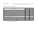
FIGURE (1/4) Fig. No. Title Page 2-1 Pin Input/Output Circuit of List ............................................................................................ 23 3-1 Memory Map (µPD78081) .................................................................................................. 25 3-2 Memory Map (µPD78082) .................................................................................................. 26 3-3 Memory Map (µPD78P083) .................................................
FIGURE (2/4) Fig. No. Title Page 6-10 8-Bit Timer Mode Control Register Setting for External Event Counter Operation ............. 93 6-11 External Event Counter Operation Timings (with Rising Edge Specification) .................... 93 6-12 8-Bit Timer Mode Control Register Settings for Square-Wave Output Operation .............. 94 6-13 8-Bit Timer Mode Control Register Settings for PWM Output Operation ...........................
FIGURE (3/4) Fig. No. Title Page 11-6 Baud Rate Generator Control Register Format (2/2) ......................................................... 145 11-7 Asynchronous Serial Interface Transmit/Receive Data Format .......................................... 157 11-8 Asynchronous Serial Interface Transmission Completion Interrupt Request Timing .......... 159 11-9 Asynchronous Serial Interface Reception Completion Interrupt Request Timing ............... 160 11-10 Receive Error Timing .......
FIGURE (4/4) Fig. No. Title Page 15-6 PROM Read Timing ........................................................................................................... 213 A-1 Development Tool Configuration ........................................................................................ 232 A-2 EV-9200G-44 Drawing (For Reference Only) ..................................................................... 241 A-3 EV-9200G-44 Footprint (For Reference Only) .....................................
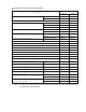
TABLE (1/2) Table. No. 1-1 Title Page Differences between the µPD78081, 78082 and 78P083, the µ PD78081(A), 78082(A) and 78P083(A), and the µPD78081(A2) ............................................................................ 13 2-1 Type of Input/Output Circuit of Each Pin ............................................................................ 22 3-1 Vector Table ........................................................................................................................
TABLE (2/2) Table. No. Title Page 12-1 Interrupt Source List ........................................................................................................... 12-2 Various Flags Corresponding to Interrupt Request Sources .............................................. 175 12-3 Times from Maskable Interrupt Request Generation to Interrupt Service .......................... 184 12-4 Interrupt Request Enabled for Multiple Interrupt during Interrupt Servicing .......................
[MEMO] – xii –
CHAPTER 1 OUTLINE CHAPTER 1 OUTLINE 1.1 Features On-chip ROM and RAM Type Part Number Note Program Memory (ROM) Data Memory (Internal High-Speed RAM) µPD78081 8 Kbytes 256 bytes µPD78082 16 Kbytes 384 bytes µPD78P083 24 Kbytes (Note) 512 bytes (Note) The capacities of internal PROM and internal high-speed RAM can be changed by means of the memory size switching register (IMS). Instruction execution time changeable from high speed (0.4 µ s: In main system clock 5.
CHAPTER 1 OUTLINE 1.2 Applications µ PD78081, 78082, 78P083: Airbags, CRT displays, keyboards, air conditioners, hot water dispensers, boilers, fan heaters, dashboards, etc. µ PD78081(A), 78082(A), 78P083(A), 78081(A2): Automobile electrical control devices, gas detector cutoff devices, various safety devices, etc. 1.
CHAPTER 1 OUTLINE 1.
CHAPTER 1 OUTLINE 1.
CHAPTER 1 • OUTLINE 44-pin plastic QFP (10 × 10 mm) µ PD78081GB-×××-3B4, 78081GB-×××-3BS-MTX µ PD78082GB-×××-3B4, 78082GB-×××-3BS-MTX µ PD78P083GB-3B4, 78P083GB-3BS-MTX µ PD78081GB(A)-×××-3B4, 78082GB(A)-×××-3B4 µ PD78P083GB(A)-3B4, 78P083GB(A)-3BS-MTXNote P11/ANI1 P10/ANI0 AVSS AVREF AVDD VDD X1 X2 IC (VPP) RESET NC µ PD78P081GB(A2)-×××-3B4 44 43 42 41 40 39 38 37 36 35 34 33 1 32 2 31 3 30 4 29 5 28 6 27 7 26 8 25 9 24 10 23 11 12 13 14 15 16 17 18 19 20 21 22 P03/INTP3 P02/INTP2 P01/INTP1 P00 P37
CHAPTER 1 OUTLINE Pin Identifications 6 ANI0 to ANI7 : Analog Input P100, P101 : Port 10 ASCK : Asynchronous Serial Clock PCL : Programmable Clock AVDD : Analog Power Supply RESET : Reset AVREF : Analog Reference Voltage RxD : Receive Data AVSS : Analog Ground SCK2 : Serial Clock BUZ : Buzzer Clock SI2 : Serial Input IC : Internally Connected SO2 : Serial Output INTP1 to INTP3 : Interrupt from Peripherals TI5, TI6 : Timer Input NC : Non-connection TO5 t
CHAPTER 1 OUTLINE (2) PROM programming mode • 42-pin plastic shrink DIP (600 mil) µ PD78P083CU, 78P083CU(A) • 42-pin ceramic shrink DIP (with window) (600 mil) µ PD78P083DU A5 A6 A7 OE CE PGM A8 (L) A9 (L) RESET VPP Open (L) VDD VDD Cautions 1. (L) 2.
CHAPTER 1 • OUTLINE 44-pin plastic QFP (10 × 10 mm) µ PD78P083GB-3B4, 78P083GB-3BS-MTX D1 D0 VSS VSS VDD VDD (L) Open VPP RESET (L) µ PD78P083GB(A)-3B4, 78P083GB(A)-3BS-MTXNote 44 43 42 41 40 39 38 37 36 35 34 33 1 32 2 31 3 30 4 29 5 28 6 27 7 26 8 25 9 24 10 23 11 12 13 14 15 16 17 18 19 20 21 22 (L) A9 (L) A8 PGM (L) A0 A1 A2 A3 A4 VSS A5 A6 A7 OE CE D2 D3 D4 D5 D6 D7 A14 A13 A12 A11 A10 Note Under development Cautions 1. (L) 2. VSS : Connect individually to VSS via a pull-down resistor.
CHAPTER 1 OUTLINE 1.6 78K/0 Series Development The following shows the 78K/0 Series products development. Subseries names are shown inside frames. Mass-produced products Products under development Y Subseries supports the I2C bus specifications.
CHAPTER 1 OUTLINE The following table shows the differences among subseries functions. Function ROM Timer D/A VDD MIN. value expansion 2 ch 3 ch (UART: 1 ch) 88 1.8 V Available 61 2.
CHAPTER 1 OUTLINE 1.
CHAPTER 1 OUTLINE 1.8 Outline of Function µ PD78081 Part Number µ PD78082 µPD78083 Item Internal memory ROM High-speed RAM Mask ROM PROM 8 Kbytes 16 Kbytes 24 KbytesNote 256 bytes 384 bytes 512 bytesNote Memory space 64 Kbytes General register 8 bits × 32 registers (8 bits × 8 registers × 4 banks) Instruction cycle Instruction execution time variable function is integrated. 0.4 µs/0.8 µs/1.6 µs/3.2 µs/6.4 µs/12.8 µs (@5.
CHAPTER 1 OUTLINE Differences between the µPD78081, 78082 and 78P083, the µPD78081(A), 78082(A) and 78P083(A), and the µPD78081(A2) 1.9 Table 1-1 Differences between the µ PD78081, 78082 and 78P083, the µPD78081(A), 78082(A) and 78P083(A), and the µ PD78081(A2) Part Number Item µ PD78081 µ PD78081(A) µ PD78082 µ PD78082(A) µ PD78P083 µ PD78P083(A) µPD78081(A2) Quality grade Standard Special Supply voltage VDD = 1.8 to 5.5 V VDD = 4.5 to 5.
CHAPTER 1 [MEMO] 14 OUTLINE
CHAPTER 2 PIN FUNCTION CHAPTER 2 PIN FUNCTION 2.1 Pin Function List 2.1.1 Normal operating mode pins (1) Port pins Pin Name Input/Output Function P00 Input Port 0 P01 Input/output 4-bit input/output port After Reset Input only Input Input/output is specifiable Input Alternate Function — INTP1 P02 bit-wise. When used as the INTP2 P03 input port, it is possible to INTP3 connect a pull-up resistor by software.
CHAPTER 2 PIN FUNCTION (2) Pins other than port pins Pin Name INTP1 Input/Output Input Function External interrupt request input by which the active edge After Reset Alternate Function Input P01 INTP2 (rising edge, falling edge, or both rising and falling edges) P02 INTP3 can be specified. P03 SI2 Input Serial interface serial data input. Input P70/RxD SO2 Output Serial interface serial data output. Input P71/TxD SCK2 Input/output Serial interface serial clock input/output.
CHAPTER 2 PIN FUNCTION 2.2 Description of Pin Functions 2.2.1 P00 to P03 (Port 0) These are 4-bit input/output ports. Besides serving as input/output ports, they function as an external interrupt request input. The following operating modes can be specified bit-wise. (1) Port mode P00 functions as input-only port and P01 to P03 function as input/output ports. P01 to P03 can be specified for input or output ports bit-wise with a port mode register 0 (PM0).
CHAPTER 2 PIN FUNCTION 2.2.3 P30 to P37 (Port 3) These are 8-bit input/output ports. Beside serving as input/output ports, they function as clock output and buzzer output. The following operating modes can be specified bit-wise. (1) Port mode These ports function as 8-bit input/output ports. They can be specified bit-wise as input or output ports with port mode register 3 (PM3).
CHAPTER 2 PIN FUNCTION 2.2.5 P70 to P72 (Port 7) This is a 3-bit input/output port. In addition to its use as an input/output port, it also has serial interface data input/ output and clock input/output functions. The following operating modes can be specified bit-wise. (1) Port mode Port 7 functions as a 3-bit input/output port. Bit-wise specification as an input port or output port is possible by means of port mode register 7 (PM7).
CHAPTER 2 PIN FUNCTION 2.2.7 AVREF A/D converter reference voltage input pin. When A/D converter is not used, connect this pin to VSS. 2.2.8 AV DD Analog power supply pin of A/D converter. Always use the same voltage as that of the V DD pin even when A/D converter is not used. 2.2.9 AVSS This is a ground voltage pin of A/D converter. Always use the same voltage as that of the VSS pin even when A/ D converter is not used. 2.2.10 RESET This is a low-level active system reset input pin. 2.2.
CHAPTER 2 PIN FUNCTION 2.2.15 IC (Mask ROM version only) The IC (Internally Connected) pin is provided to set the test mode to check the µ PD78083 Subseries at delivery. Connect it directly to the VSS with the shortest possible wire in the normal operating mode. When a voltage difference is produced between the IC pin and VSS pin because the wiring between those two pins is too long or an external noise is input to the IC pin, the user's program may not run normally. Connect IC pins to VSS pins directly.
CHAPTER 2 PIN FUNCTION 2.3 Pin Input/Output Circuits and Recommended Connection of Unused Pins Types of input/output circuits of the pins and recommeded connection of unused pins are shown in Table 2-1. For the configuration of each type of input/output circuit, see Figure 2-1. Table 2-1. Type of Input/Output Circuit of Each Pin Pin Name Input/Output Input/Output Recommended Connection for Unused Pins Circuit Type P00 2 Input Connect to V SS .
CHAPTER 2 PIN FUNCTION Figure 2-1.
CHAPTER 2 [MEMO] 24 PIN FUNCTION
CHAPTER 3 CPU ARCHITECTURE CHAPTER 3 CPU ARCHITECTURE 3.1 Memory Spaces Figures 3-1 to 3-3 shows memory maps. Figure 3-1.
CHAPTER 3 CPU ARCHITECTURE Figure 3-2.
CHAPTER 3 CPU ARCHITECTURE Figure 3-3.
CHAPTER 3 CPU ARCHITECTURE 3.1.1 Internal program memory space The internal program memory is mask ROM with a 8192 × 8-bit configuration in the µPD78081, and a 16384 × 8-bit configuration in the µPD78082, and PROM with a 24576 × 8-bit configuration in the µPD78P083. The internal program memory space stores programs and table data. Normally, they are addressed with a program counter (PC). The internal program memory is divided into the following three areas.
CHAPTER 3 CPU ARCHITECTURE 3.1.2 Internal data memory space The internal high speed RAM configuration is 256 × 8-bit in the µ PD78081, 384 × 8-bit in the µPD78082 and 512 × 8-bit in the µ PD8P083. In this area, four banks of general registers, each bank consisting of eight 8-bit registers, are allocated in the 32-byte area FEE0H to FEFFH. The internal high-speed RAM can also be used as a stack memory area. 3.1.
CHAPTER 3 CPU ARCHITECTURE Figure 3-4.
CHAPTER 3 CPU ARCHITECTURE Figure 3-5.
CHAPTER 3 CPU ARCHITECTURE Figure 3-6.
CHAPTER 3 CPU ARCHITECTURE 3.2 Processor Registers The µPD78083 subseries units incorporate the following processor registers. 3.2.1 Control registers The control registers control the program sequence, statuses and stack memory. The control registers consist of a program counter, a program status word and a stack pointer. (1) Program counter (PC) The program counter is a 16-bit register which holds the address information of the next program to be executed.
CHAPTER 3 CPU ARCHITECTURE (a) Interrupt enable flag (IE) This flag controls the interrupt request acknowledge operations of the CPU. When IE = 0, all interrupts except the non-maskable interrupt are disabled (DI status). When IE = 1, interrupts are enabled (EI status). At this time, acknowledgment of interrupts is controlled with an inservice priority flag (ISP), an interrupt mask flag for various interrupt sources, and a priority specify flag.
CHAPTER 3 CPU ARCHITECTURE (3) Stack pointer (SP) This is a 16-bit register to hold the start address of the memory stack area. Only the internal high-speed RAM area (FE00H-FEFFH for the µ PD78081, FD80H-FEFFH for the µPD78082, and FD00H-FEFFH for the µ PD78P083) can be set as the stack area. Figure 3-9. Stack Pointer Configuration 15 0 SP The SP is decremented ahead of write (save) to the stack memory and is incremented after read (reset) from the stack memory.
CHAPTER 3 CPU ARCHITECTURE 3.2.2 General registers A general register is mapped at particular addresses (FEE0H to FEFFH) of the data memory. It consists of 4 banks, each bank consisting of eight 8-bit registers (X, A, C, B, E, D, L and H). Each register can also be used as an 8-bit register. Two 8-bit registers can be used in pairs as a 16-bit register (AX, BC, DE and HL).
CHAPTER 3 CPU ARCHITECTURE 3.2.3 Special Function Register (SFR) Unlike a general register, each special-function register has special functions. It is allocated in the FF00H to FFFFH area. The special-function register can be manipulated like the general register, with the operation, transfer and bit manipulation instructions. Manipulatable bit units, 1, 8 and 16, depend on the special-function register type. Each manipulation bit unit can be specified as follows.
CHAPTER 3 CPU ARCHITECTURE Table 3-2.
CHAPTER 3 CPU ARCHITECTURE Table 3-2.
CHAPTER 3 CPU ARCHITECTURE 3.3 Instruction Address Addressing An instruction address is determined by program counter (PC) contents. The contents of PC are normally incremented (+1 for each byte) automatically according to the number of bytes of an instruction to be fetched each time another instruction is executed. When a branch instruction is executed, the branch destination information is set to the PC and branched by the following addressing.
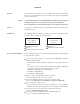
CHAPTER 3 CPU ARCHITECTURE 3.3.2 Immediate addressing [Function] Immediate data in the instruction word is transferred to the program counter (PC) and branched. This function is carried out when the CALL !addr16 or BR !addr16 or CALLF !addr11 instruction is executed. The CALL !addr16 and BR !addr16 instruction can branch in the entire memory space. The CALLF !addr11 instruction branches to an area of addresses 0800H through 0FFFH.
CHAPTER 3 CPU ARCHITECTURE 3.3.3 Table indirect addressing [Function] Table contents (branch destination address) of the particular location to be addressed by bits 1 to 5 of the immediate data of an operation code are transferred to the program counter (PC) and branched. Before the CALLT [addr5] instruction is executed, table indirect addressing is performed. This instruction references an address stored in the memory table at addresses 40H through 7FH, and can branch in the entire memory space.
CHAPTER 3 CPU ARCHITECTURE 3.3.4 Register addressing [Function] Register pair (AX) contents to be specified with an instruction word are transferred to the program counter (PC) and branched. This function is carried out when the BR AX instruction is executed.
CHAPTER 3 CPU ARCHITECTURE 3.4 Operand Address Addressing The following various methods are available to specify the register and memory (addressing) which undergo manipulation during instruction execution. 3.4.1 Implied addressing [Function] The register which functions as an accumulator (A and AX) in the general register is automatically (illicitly) addressed. Of the µ PD78083 Subseries instruction words, the following instructions employ implied addressing.
CHAPTER 3 CPU ARCHITECTURE 3.4.2 Register addressing [Function] This addressing accesses a general register as an operand. The general register accessed is specified by the register bank select flags (RBS0 and RBS1) and register specify code (Rn or RPn) in an instruction code. Register addressing is carried out when an instruction with the following operand format is executed. When an 8-bit register is specified, one of the eight registers is specified with 3 bits in the operation code.
CHAPTER 3 CPU ARCHITECTURE 3.4.3 Direct addressing [Function] This addressing directly addresses the memory indicated by the immediate data in an instruction word.
CHAPTER 3 CPU ARCHITECTURE 3.4.4 Short direct addressing [Function] The memory to be manipulated in the fixed space is directly addressed with 8-bit data in an instruction word. The fixed space to which this address is applied is a 256-byte space of addresses FE20H through FF1FH. An internal high-speed RAM and a special-function register (SFR) are mapped at FE20H to FEFFH and FF00H to FF1FH, respectively.
CHAPTER 3 CPU ARCHITECTURE [Description example] MOV 0FE30H, #50H; when setting saddr to FE30H and immediate data to 50H Operation code 0 0 0 1 0 0 0 1 OP code 0 0 1 1 0 0 0 0 30H (saddr-offset) 0 1 0 1 0 0 0 0 50H (immediate data) [Illustration] 7 0 OP code saddr-offset Short Direct Memory 15 Effective Address 1 8 7 1 1 1 1 1 1 α When 8-bit immediate data is 20H to FFH, α = 0 When 8-bit immediate data is 00H to 1FH, α = 1 48 0
CHAPTER 3 CPU ARCHITECTURE 3.4.5 Special-Function Register (SFR) addressing [Function] The memory-mapped special-function register (SFR) is addressed with 8-bit immediate data in an instruction word. This addressing is applied to the 240-byte spaces FF00H to FFCFH and FFE0H to FFFFH. However, the SFR mapped at FF00H to FF1FH can be accessed with short direct addressing.
CHAPTER 3 CPU ARCHITECTURE 3.4.6 Register indirect addressing [Function] This addressing addresses the memory with the contents of a register pair specified as an operand. The register pair to be accessed is specified by the register bank select flags (RBS0 and RBS1) and register pair specify code in an instruction code. This addressing can be carried out for all the memory spaces.
CHAPTER 3 CPU ARCHITECTURE 3.4.7 Based addressing [Function] This addressing addresses the memory by adding 8-bit immediate data to the contents of the HL register pair which is used as a base register and by using the result of the addition. The HL register pair to be accessed is in the register bank specified by the register bank select flags (RBS0 and RBS1). Addition is performed by expanding the offset data as a positive number to 16 bits. A carry from the 16th bit is ignored.
CHAPTER 3 CPU ARCHITECTURE 3.4.8 Based indexed addressing [Function] This addressing addresses the memory by adding the contents of the HL register, which is used as a base register, to the contents of the B or C register specified in the instruction word, and by using the result of the addition. The HL, B, and C registers to be accessed are registers in the register bank specified by the register bank select flags (RBS0 and RBS1).
CHAPTER 4 PORT FUNCTIONS CHAPTER 4 PORT FUNCTIONS 4.1 Port Functions The µPD78083 Subseries units incorporate an input port and thirty-two input/output ports. Figure 4-1 shows the port configuration. Every port is capable of 1-bit and 8-bit manipulations and can carry out considerably varied control operations. Besides port functions, the ports can also serve as on-chip hardware input/output pins. Figure 4-1.
CHAPTER 4 PORT FUNCTIONS Table 4-1. Port Functions Pin Name Input/Output Function Dual-Function Pin P00 Input Port 0 Input only P01 Input/output 4-bit input/output port Input/output is specifiable bit-wise. When INTP1 used as the input port, it is possible to connect INTP2 P02 P03 P10-P17 a pull-up resistor by software. Input/output Port 1 — INTP3 ANI0-ANI7 8-bit input/output port Input/output is specifiable bit-wise.
CHAPTER 4 PORT FUNCTIONS 4.2 Port Configuration A port consists of the following hardware: Table 4-2. Port Configuration Item Control register Configuration Port mode register (PMm: m = 0, 1, 3, 5, 7, 10) Pull-up resistor option register (PUOH, PUOL) Port Total: 33 ports (1 input, 32 inputs/outputs) Pull-up resistor Total: 32 (software specifiable) 4.2.1 Port 0 Port 0 is an 4-bit input/output port with output latch.
CHAPTER 4 PORT FUNCTIONS Figure 4-2. P00 Block Diagram Internal bus RD P00 Figure 4-3.
CHAPTER 4 PORT FUNCTIONS 4.2.2 Port 1 Port 1 is an 8-bit input/output port with output latch. It can specify the input mode/output mode in 1-bit units with a port mode register 1 (PM1). When P10 to P17 pins are used as input ports, an on-chip pull-up resistor can be used to them in 8-bit units with a pull-up resistor option register L (PUOL). Dual-functions include an A/D converter analog input. RESET input sets port 1 to input mode. Figure 4-4 shows a block diagram of port 1.
CHAPTER 4 PORT FUNCTIONS 4.2.3 Port 3 Port 3 is an 8-bit input/output port with output latch. P30 to P37 pins can specify the input mode/output mode in 1-bit units with the port mode register 3 (PM3). When P30 to P37 pins are used as input ports, an on-chip pull-up resistor can be used to them in 8-bit units with a pull-up resistor option register L (PUOL). Dual-functions include clock output and buzzer output. RESET input sets port 3 to input mode. Figure 4-5 shows a block diagram of port 3. Figure 4-5.
CHAPTER 4 PORT FUNCTIONS 4.2.4 Port 5 Port 5 is an 8-bit input/output port with output latch. P50 to P57 pins can specify the input mode/output mode in 1-bit units with the port mode register 5 (PM5). When P50 to P57 pins are used as input ports, an on-chip pull-up resistor can be used to them in 8-bit units with a pull-up resistor option register L (PUOL). A maximum of 7 out of 8 ports can drive LEDs directly. RESET input sets port 5 to input mode. Figure 4-6 shows a block diagram of port 5. Figure 4-6.
CHAPTER 4 PORT FUNCTIONS 4.2.5 Port 7 This is a 3-bit input/output port with output latches. Input mode/output mode can be specified bit-wise by means of port mode register 7 (PM7). When pins P70 to P72 are used as input port pins, an on-chip pull-up resistor can be used as a 3-bit unit by means of pull-up resistor option register L (PUOL). Dual-functions include serial interface channel 2 data input/output and clock input/output. RESET input sets the input mode.
CHAPTER 4 PORT FUNCTIONS Figure 4-8.
CHAPTER 4 PORT FUNCTIONS 4.2.6 Port 10 This is an 2-bit input/output port with output latches. Input mode/output mode can be specified bit-wise by means of port mode register 10 (PM10). When pins P100 to P101 are used as input port pins, an on-chip pull-up resistor can be used as an 2-bit unit by means of pull-up resistor option register H (PUOH). These pins are dual function pins and serve as timer inputs/outputs. RESET input sets the input mode. The port 10 block diagram is shown in Figure 4-9.
CHAPTER 4 PORT FUNCTIONS 4.3 Port Function Control Registers The following two types of registers control the ports. • Port mode registers (PM0, PM1, PM3, PM5, PM7, PM10) • Pull-up resistor option register (PUOH, PUOL) (1) Port mode registers (PM0, PM1, PM3, PM5, PM7, PM10) These registers are used to set port input/output in 1-bit units. PM0, PM1, PM3, PM5, PM7, PM10 are independently set with a 1-bit or 8-bit memory manipulation instruction RESET input sets registers to FFH.
CHAPTER 4 PORT FUNCTIONS Table 4-3.
CHAPTER 4 PORT FUNCTIONS Figure 4-10.
CHAPTER 4 PORT FUNCTIONS (2) Pull-up resistor option register (PUOH, PUOL) This register is used to set whether to use an internal pull-up resistor at each port or not. A pull-up resistor is internally used at bits which are set to the input mode at a port where on-chip pull-up resistor use has been specified with PUOH, PUOL. No on-chip pull-up resistors can be used to the bits set to the output mode or to the bits used as an analog input pin, irrespective of PUOH or PUOL setting.
CHAPTER 4 PORT FUNCTIONS 4.4 Port Function Operations Port operations differ depending on whether the input or output mode is set, as shown below. 4.4.1 Writing to input/output port (1) Output mode A value is written to the output latch by a transfer instruction, and the output latch contents are output from the pin. Once data is written to the output latch, it is retained until data is written to the output latch again.
CHAPTER 4 [MEMO] 68 PORT FUNCTIONS
CHAPTER 5 CLOCK GENERATOR CHAPTER 5 CLOCK GENERATOR 5.1 Clock Generator Functions The clock generator generates the clock to be supplied to the CPU and peripheral hardware. The following type of system clock oscillator is available. Main system clock oscillator This circuit oscillates at frequencies of 1 to 5.0 MHz. Oscillation can be stopped by executing the STOP instruction. 5.2 Clock Generator Configuration The clock generator consists of the following hardware. Table 5-1.
CHAPTER 5 CLOCK GENERATOR Figure 5-1.
CHAPTER 5 CLOCK GENERATOR 5.3 Clock Generator Control Register The clock generator is controlled by the following two registers: • Processor clock control register (PCC) • Oscillation mode selection register (OSMS) (1) Processor clock control register (PCC) The PCC sets whether to use CPU clock selection and the ratio of division. The PCC is set with a 1-bit or 8-bit memory manipulation instruction. RESET input sets the PCC to 04H. Figure 5-2.
CHAPTER 5 CLOCK GENERATOR (2) Oscillation mode selection register (OSMS) This register specifies whether the clock output from the main system clock oscillator without passing through the scaler is used as the main system clock, or the clock output via the scaler is used as the main system clock. OSMS is set with 8-bit memory manipulation instruction. RESET input sets OSMS to 00H. Figure 5-3.
CHAPTER 5 CLOCK GENERATOR 5.4 System Clock Oscillator 5.4.1 Main system clock oscillator The main system clock oscillator oscillates with a crystal resonator or a ceramic resonator (standard: 5.0 MHz) connected to the X1 and X2 pins. External clocks can be input to the main system clock oscillator. In this case, input a clock signal to the X1 pin and an antiphase clock signal to the X2 pin. Figure 5-5 shows an external circuit of the main system clock oscillator. Figure 5-5.
CHAPTER 5 CLOCK GENERATOR Figure 5-6.
CHAPTER 5 CLOCK GENERATOR Figure 5-6. Examples of Oscillator with Bad Connection (2/2) (c) Signals are fetched IC X2 X1 5.4.2 Scaler The scaler divides the main system clock oscillator output (fXX ) and generates various clocks.
CHAPTER 5 CLOCK GENERATOR 5.5 Clock Generator Operations The clock generator generates the following various types of clocks and controls the CPU operating mode including the standby mode. • Main system clock • CPU clock fXX fCPU • Clock to peripheral hardware The following clock generator functions and operations are determined with the processor clock control register (PCC) and the oscillation mode selection register (OSMS).
CHAPTER 5 CLOCK GENERATOR 5.6 Changing CPU Clock Settings 5.6.1 Time required for CPU clock switchover The CPU clock can be switched over by means of bits 0 to 2 (PCC0 to PCC2) of the processor clock control register (PCC). The actual switchover operation is not performed directly after writing to the PCC, but operation continues on the pre-switchover clock for several instructions (see Table 5-2). Table 5-2.
CHAPTER 5 CLOCK GENERATOR 5.6.2 CPU clock switching procedure This section describes CPU clock switching procedure. Figure 5-7. CPU Clock Switching VDD RESET CPU Clock Minimum Maximum Speed Operation Speed Operation Wait (26.2 ms : 5.0 MHz) Internal Reset Operation (1) The CPU is reset by setting the RESET signal to low level after power-on. After that, when reset is released by setting the RESET signal to high level, main system clock starts oscillation.
CHAPTER 6 8-BIT TIMER/EVENT COUNTERS 5 AND 6 CHAPTER 6 8-BIT TIMER/EVENT COUNTERS 5 AND 6 The timers incorporated into the µ PD78083 subseries are outlined below. (1) 8-bit timers/event counters 5 and 6 (TM5 and TM6) This can be used to serve as an interval timer, an external event counter, square wave output with any selected frequency PWM, etc. It cannot be used as a 16-bit timer/event counter (See CHAPTER 6 8-BIT TIMER/EVENT COUNTERS 5 AND 6).
CHAPTER 6 8-BIT TIMER/EVENT COUNTERS 5 AND 6 6.1 8-Bit Timer/Event Counters 5 and 6 Functions The 8-bit timer/event counters 5 and 6 (TM5 and TM6) have the following functions. • Interval timer • External event counter • Square-wave output • PWM output (1) 8-bit interval timer Interrupt requests are generated at the preset time intervals. Table 6-2.
CHAPTER 6 8-BIT TIMER/EVENT COUNTERS 5 AND 6 (2) External event counter The number of pulses of an externally input signal can be measured. (3) Square-wave output A square wave with any selected frequency can be output. Table 6-3. 8-Bit Timer/Event Counters 5 and 6 Square-Wave Output Ranges Minimum pulse width MCS = 1 MCS = 0 1/fX — (200 ns) Maximum pulse width MCS = 1 MCS = 0 2 8 × 1/fX — (51.
CHAPTER 6 8-BIT TIMER/EVENT COUNTERS 5 AND 6 6.2 8-Bit Timer/Event Counters 5 and 6 Configurations The 8-bit timer/event counters 5 and 6 consist of the following hardware. Table 6-4.
CHAPTER 6 8-BIT TIMER/EVENT COUNTERS 5 AND 6 Figure 6-2. Block Diagram of 8-Bit Timer/Event Counters 5 and 6 Output Control Circuit TMCn1 TMCn6 LVRn R LVSn S Selector RESET Q TMCn1 TO5/P100/TI5, TO6/P101/TI6 INV P100, P101 Output Latch TMCn6 INTTMn PM100, PM101Note PWM Output Circuit Timer Output F/F2 TCEn INTTMn R OVFn S Q Level Invert TOEn Note PM100 : Bit 0 of port mode register 10 (PM10) PM101 : Bit 1 of PM10 Remarks 1.
CHAPTER 6 8-BIT TIMER/EVENT COUNTERS 5 AND 6 (1) Compare registers 50 and 60 (CR50, CR60) These are 8-bit registers to compare the value set to CR50 to the 8-bit timer register 5 (TM5) count value, and the value set to CR60 to the 8-bit timer register 6 (TM6) count value, and, if they match, generate an interrupt request (INTTM5 and INTTM6, respectively). CR50 and CR60 are set with an 8-bit memory manipulation instruction. They cannot be set with a 16-bit memory manipulation instruction.
CHAPTER 6 8-BIT TIMER/EVENT COUNTERS 5 AND 6 Figure 6-3.
CHAPTER 6 8-BIT TIMER/EVENT COUNTERS 5 AND 6 (2) Timer clock select register 6 (TCL6) This register sets count clocks of 8-bit timer register 6. TCL6 is set with an 8-bit memory manipulation instruction. RESET input sets TCL6 to 00H. Figure 6-4.
CHAPTER 6 8-BIT TIMER/EVENT COUNTERS 5 AND 6 (3) 8-bit timer mode control register 5 (TMC5) This register enables/stops operation of 8-bit timer register 5, sets the operating mode of 8-bit timer register 5 and controls operation of 8-bit timer/event counter 5 output control circuit. It sets R-S type flip-flop (timer output F/F 1,2) setting/resetting, the active level in PWM mode, inversion enabling/disabling in modes other than PWM mode and 8-bit timer/event counter 5 timer output enabling/ disabling.
CHAPTER 6 8-BIT TIMER/EVENT COUNTERS 5 AND 6 (4) 8-bit timer mode control register 6 (TMC6) This register enables/stops operation of 8-bit timer register 6, sets the operating mode of 8-bit timer register 6 and controls operation of 8-bit timer/event counter 6 output control circuit. It sets R-S type flip-flop (timer output F/F 1,2) setting/resetting, active level in PWM mode, inversion enabling/ disabling in modes other than PWM mode and 8-bit timer/event counter 6 timer output enabling/disabling.
CHAPTER 6 8-BIT TIMER/EVENT COUNTERS 5 AND 6 (5) Port mode register 10 (PM10) This register sets port 10 input/output in 1-bit units. When using the P100/TI5/TO5 and P101/TI6/TO6 pins for timer output, set PM100, PM101, and output latches of P100 and P101 to 0. PM10 is set with a 1-bit or 8-bit memory manipulation instruction. RESET input sets PM10 to FFH. Figure 6-7.
CHAPTER 6 8-BIT TIMER/EVENT COUNTERS 5 AND 6 6.4 8-Bit Timer/Event Counters 5 and 6 Operations 6.4.1 Interval timer operations By setting the 8-bit timer mode control registers 5 and 6 (TMC5 and TMC6) as shown in Figure 6-8, it can be operated as an interval timer. The 8-bit timer/event counters 5 and 6 operate as interval timers which generate interrupt requests repeatedly at intervals of the count value preset to 8-bit compare registers 50 and 60 (CR50 and CR60).
CHAPTER 6 8-BIT TIMER/EVENT COUNTERS 5 AND 6 Figure 6-9. Interval Timer Operation Timings t Count Clock TMn Count Value 00 01 N 00 01 N 00 01 N Clear Clear CRn0 N N N N TCEn Count start INTTMn Interrupt Request Acknowledge Interrupt Request Acknowledge TOn Interval Time Interval Time Interval Time Remarks 1. Interval time = (N + 1) × t : N = 00H to FFH 2.
CHAPTER 6 8-BIT TIMER/EVENT COUNTERS 5 AND 6 Table 6-5. 8-Bit Timer/Event Counters 5 and 6 Interval Times Minimum Interval Time Maximum Interval Time MCS = 1 MCS = 1 Resolution TCLn3 TCLn2 TCLn1 TCLn0 0 0 0 0 0 0 0 1 0 1 0 0 0 1 0 1 0 1 1 0 0 1 1 1 1 0 0 0 1 0 0 1 1 0 1 0 1 0 1 1 1 1 0 0 1 1 0 1 1 1 1 0 1 1 1 1 Other than above Remarks 1.
CHAPTER 6 8-BIT TIMER/EVENT COUNTERS 5 AND 6 6.4.2 External event counter operation The external event counter counts the number of external clock pulses to be input to the TI5/PI00/TO5 and TI6/ P101/TO6 pins with 8-bit timer registers 5 and 6 (TM5 and TM6). TM5 and TM6 are incremented each time the valid edge specified with the timer clock select register 5 and 6 (TCL5 and TCL6) is input. Either the rising or falling edge can be selected.
CHAPTER 6 8-BIT TIMER/EVENT COUNTERS 5 AND 6 6.4.3 Square-wave output This makes the value set in advance in the 8-bit conveyor register 50, 60 (CR50, CR60) to be the interval. It operates as a square wave output at the desired frequency.
CHAPTER 6 8-BIT TIMER/EVENT COUNTERS 5 AND 6 Table 6-6. 8-Bit Timer/Event Counters 5 and 6 Square-Wave Output Ranges Minimum Pulse Width Maximum Pulse Width Resolution MCS = 1 MCS = 0 MCS = 1 MCS = 0 MCS = 1 — 1/fX — 2 8 × 1/fX — (51.2 µ s) (200 ns) MCS = 0 1/fX (200 ns) 1/fX 2 × 1/fX 2 8 × 1/fX 2 9 × 1/fX 1/fX 2 × 1/fX (200 ns) (400 ns) (51.2 µ s) (102.4 µ s) (200 ns) (400 ns) 2 × 1/fX 2 2 × 1/fX 2 9 × 1/fX 2 10 × 1/fX 2 × 1/fX 2 2 × 1/fX (400 ns) (800 ns) (102.
CHAPTER 6 8-BIT TIMER/EVENT COUNTERS 5 AND 6 6.4.4 PWM output operations Setting the 8-bit timer mode control registers 5 and 6 (TMC5 and TMC6) as shown in Figure 6-13 allows operation as PWM output. Pulses with the duty ratio determined by the values preset in the 8-bit compare registers 50 and 60 (CR50 and CR60) output from the TO5/P100/TI5 or TO6/P101/TI6 pin.
CHAPTER 6 8-BIT TIMER/EVENT COUNTERS 5 AND 6 Figure 6-14. PWM Output Operation Timing (Active high setting) CRn0 Changing (M→N) Count Clock TMn Count Value 00 CRn0 01 02 FF 00 M 01 02 N N+1 N N+2 N+3 00 N TCEn INTTMn OVFn TOn Inactive Level Inactive Level Remark Active Level Inactive Level n = 5, 6 Figure 6-15.
CHAPTER 6 8-BIT TIMER/EVENT COUNTERS 5 AND 6 Figure 6-16.
FF N 00 02 Active Level 01 N N+2 Inactive Level N N+1 FF 00 M 02 Active Level 01 Remark n = 5, 6 Caution If CRn0 is changed during TMn operation, the value changed is not reflected until TMn overflows. TOn OVFn INTTMn TCEn CRn0 TMn Count Value Count Clock CRn0 Changing (N→M) M Figure 6-17.
CHAPTER 6 8-BIT TIMER/EVENT COUNTERS 5 AND 6 6.5 Cautions on 8-Bit Timer/Event Counters 5 and 6 (1) Timer start errors An error with a maximum of one clock may occur concerning the time required for a match signal to be generated after timer start. This is because 8-bit timer registers 5 and 6 (TM5 and TM6) are started asynchronously with the count pulse. Figure 6-18.
CHAPTER 6 8-BIT TIMER/EVENT COUNTERS 5 AND 6 (3) Operation after compare register change during timer count operation If the values after the 8-bit compare registers 50 and 60 (CR50 and CR60) are changed are smaller than those of 8-bit timer registers 5 and 6 (TM5 and TM6), TM5 and TM6 continue counting, overflow and then restart counting from 0. Thus, if the value (M) after CR50 and CR60 change is smaller than value (N) before the change, it is necessary to restart the timer after changing CR50 and CR60.
CHAPTER 6 [MEMO] 102 8-BIT TIMER/EVENT COUNTERS 5 AND 6
CHAPTER 7 WATCHDOG TIMER CHAPTER 7 WATCHDOG TIMER 7.1 Watchdog Timer Functions The watchdog timer has the following functions. • Watchdog timer • Interval timer Caution Select the watchdog timer mode or the interval timer mode with the watchdog timer mode register (WDTM) (The watchdog timer and interval timer cannot be used at the same time). (1) Watchdog timer mode An inadvertent program loop is detected.
CHAPTER 7 WATCHDOG TIMER (2) Interval timer mode Interrupt requests are generated at the preset time intervals. Table 7-2. Interval Times Interval Time MCS = 1 CS = 0 211 × 1/fXX 211 × 1/fX (410 µs) 212 × 1/fX (819 µs) 212 × 1/fXX 212 × 1/fX (819 µs) 213 × 1/fX (1.64 ms) 213 × 1/fXX 213 × 1/fX (1.64 ms) 214 × 1/fX (3.28 ms) 214 × 1/fXX 214 × 1/fX (3.28 ms) 215 × 1/fX (6.55 ms) 215 × 1/fXX 215 × 1/fX (6.55 ms) 216 × 1/fX (13.1 ms) 216 × 1/fXX 216 × 1/fX (13.1 ms) 217 × 1/fX (26.
CHAPTER 7 WATCHDOG TIMER 7.2 Watchdog Timer Configuration The watchdog timer consists of the following hardware. Table 7-3. Watchdog Timer Configuration Item Configuration Control register Timer clock select register 2 (TCL2) Watchdog timer mode register (WDTM) Figure 7-1.
CHAPTER 7 WATCHDOG TIMER 7.3 Watchdog Timer Control Registers The following two types of registers are used to control the watchdog timer. • Timer clock select register 2 (TCL2) • Watchdog timer mode register (WDTM) (1) Timer clock select register 2 (TCL2) This register sets the watchdog timer count clock. TCL2 is set with 8-bit memory manipulation instruction. RESET input sets TCL2 to 00H. Remark 106 Besides setting the watchdog timer count clock, TCL2 sets the buzzer output frequency.
CHAPTER 7 WATCHDOG TIMER Figure 7-2. Timer Clock Select Register 2 Format Symbol 7 6 5 TCL2 TCL27 TCL26 TCL25 4 3 0 0 2 1 0 TCL22 TCL21 TCL20 Address FF42H After Reset 00H R/W R/W Watchdog Timer Count Clock Selection TCL22 TCL21 TCL20 MCS=1 MCS=0 0 0 0 f XX /2 3 f X /23 (625 kHz) f X /24 (313 kHz) 0 0 1 f XX /24 f X /24 (313 kHz) f X /25 (156 kHz) 0 1 0 f XX /25 f X /25 (156 kHz) f X /26 (78.1 kHz) 0 1 1 f XX /26 f X /26 (78.1 kHz) f X /27 (39.
CHAPTER 7 WATCHDOG TIMER (2) Watchdog timer mode register (WDTM) This register sets the watchdog timer operating mode and enables/disables counting. WDTM is set with a 1-bit or 8-bit memory manipulation instruction. RESET input sets WDTM to 00H. Figure 7-3.
CHAPTER 7 WATCHDOG TIMER 7.4 Watchdog Timer Operations 7.4.1 Watchdog timer operation When bit 4 (WDTM4) of the watchdog timer mode register (WDTM) is set to 1, the watchdog timer is operated to detect any inadvertent program loop. The watchdog timer count clock (inadvertent program loop detection time interval) can be selected with bits 0 to 2 (TCL20 to TCL22) of the timer clock select register 2 (TCL2). Watchdog timer starts by setting bit 7 (RUN) of WDTM to 1.
CHAPTER 7 WATCHDOG TIMER 7.4.2 Interval timer operation The watchdog timer operates as an interval timer which generates interrupt requests repeatedly at an interval of the preset count value when bit 4 (WDTM4) of the watchdog timer mode register (WDTM) is set to 0. A count clock (interval time) can be selected by the bits 0 to 2 (TCL20 to TCL22) of the timer clock select register 2 (TCL2). By setting the bit 7 (RUN) of WDTM to 1, the watchdog timer starts operating as an interval timer.
CHAPTER 8 CLOCK OUTPUT CONTROL CIRCUIT CHAPTER 8 CLOCK OUTPUT CONTROL CIRCUIT 8.1 Clock Output Control Circuit Functions The clock output control circuit is intended for carrier output during remote controlled transmission and clock output for supply to peripheral LSI. Clocks selected with the timer clock select register 0 (TCL0) are output from the PCL/ P35 pin. Follow the procedure below to output clock pulses.
CHAPTER 8 CLOCK OUTPUT CONTROL CIRCUIT 8.2 Clock Output Control Circuit Configuration The clock output control circuit consists of the following hardware. Table 8-1. Clock Output Control Circuit Configuration Item Control register Configuration Timer clock select register 0 (TCL0) Port mode register 3 (PM3) Figure 8-2.
CHAPTER 8 CLOCK OUTPUT CONTROL CIRCUIT 8.3 Clock Output Function Control Registers The following two types of registers are used to control the clock output function. • Timer clock select register 0 (TCL0) • Port mode register 3 (PM3) (1) Timer clock select register 0 (TCL0) This register sets PCL output clock. TCL0 is set with a 1-bit or 8-bit memory manipulation instruction. RESET input sets TCL0 to 00H. Figure 8-3.
CHAPTER 8 CLOCK OUTPUT CONTROL CIRCUIT (2) Port mode register 3 (PM3) This register set port 3 input/output in 1-bit units. When using the P35/PCL pin for clock output function, set PM35 and output latch of P35 to 0. PM3 is set with a 1-bit or 8-bit memory manipulation instruction. RESET input sets PM3 to FFH. Figure 8-4.
CHAPTER 9 BUZZER OUTPUT CONTROL CIRCUIT CHAPTER 9 BUZZER OUTPUT CONTROL CIRCUIT 9.1 Buzzer Output Control Circuit Functions The buzzer output control circuit outputs 1.2 kHz, 2.4 kHz, 4.9 kHz, or 9.8 kHz frequency square waves. The buzzer frequency selected with timer clock select register 2 (TCL2) is output from the BUZ/P36 pin. Follow the procedure below to output the buzzer frequency. (1) Select the buzzer output frequency with bits 5 to 7 (TCL25 to TCL27) of TCL2. (2) Set the P36 output latch to 0.
CHAPTER 9 BUZZER OUTPUT CONTROL CIRCUIT 9.3 Buzzer Output Function Control Registers The following two types of registers are used to control the buzzer output function. • Timer clock select register 2 (TCL2) • Port mode register 3 (PM3) (1) Timer clock select register 2 (TCL2) This register sets the buzzer output frequency. TCL2 is set with an 8-bit memory manipulation instruction. RESET input sets TCL2 to 00H.
CHAPTER 9 BUZZER OUTPUT CONTROL CIRCUIT Figure 9-2. Timer Clock Select Register 2 Format Symbol 7 6 5 TCL2 TCL27 TCL26 TCL25 4 3 0 0 2 1 0 TCL22 TCL21 TCL20 Address FF42H After Reset 00H R/W R/W Watchdog Timer Count Clock Selection TCL22 TCL21 TCL20 MCS=1 3 3 MCS=0 0 0 0 f XX /2 f X /2 (625 kHz) f X /24 (313 kHz) 0 0 1 f XX /24 f X /24 (313 kHz) f X /25 (156 kHz) 0 1 0 f XX /25 f X /25 (156 kHz) f X /26 (78.1 kHz) 0 1 1 f XX /26 f X /26 (78.1 kHz) f X /27 (39.
CHAPTER 9 BUZZER OUTPUT CONTROL CIRCUIT (2) Port mode register 3 (PM3) This register sets port 3 input/output in 1-bit units. When using the P36/BUZ pin for buzzer output function, set PM36 and output latch of P36 to 0. PM3 is set with a 1-bit or 8-bit memory manipulation instruction. RESET input sets PM3 to FFH. Figure 9-3.
CHAPTER 10 A/D CONVERTER CHAPTER 10 A/D CONVERTER 10.1 A/D Converter Functions The A/D converter converts an analog input into a digital value. It consists of 8 channels (ANI0 to ANI7) with an 8-bit resolution. The conversion method is based on successive approximation and the conversion result is held in the 8-bit A/D conversion result register (ADCR). The following two ways are available to start A/D conversion. (1) Hardware start Conversion is started by trigger input (INTP3).
CHAPTER 10 A/D CONVERTER Figure 10-1.
CHAPTER 10 A/D CONVERTER (1) Successive approximation register (SAR) This register compares the analog input voltage value to the voltage tap (compare voltage) value applied from the series resistor string and holds the result from the most significant bit (MSB). When held to the least significant bit (LSB) (end of A/D conversion), the contents of the SAR are transferred to the A/D conversion results register. (2) A/D conversion result register (ADCR) This register holds the A/D conversion result.
CHAPTER 10 A/D CONVERTER 10.3 A/D Converter Control Registers The following three types of registers are used to control the A/D converter. • A/D converter mode register (ADM) • A/D converter input select register (ADIS) • External interrupt mode register 1 (INTM1) (1) A/D converter mode register (ADM) This register sets the analog input channel for A/D conversion, conversion time, conversion start/stop and external trigger. ADM is set with a 1-bit or 8-bit memory manipulation instruction.
CHAPTER 10 A/D CONVERTER Figure 10-2. A/D Converter Mode Register Format Symbol 7 6 5 ADM CS TRG FR1 4 3 2 1 0 FR0 ADM3 ADM2 ADM1 HSC ADM3 ADM2 ADM1 After Reset 01H Address FF80H R/W R/W Analog Input Channel Selection 0 0 0 ANI0 0 0 1 ANI1 0 1 0 ANI2 0 1 1 ANI3 1 0 0 ANI4 1 0 1 ANI5 1 1 0 ANI6 1 1 1 ANI7 A/D Conversion Time SelectionNote 1 FR1 FR0 HSC fX =5.
CHAPTER 10 A/D CONVERTER (2) A/D converter input select register (ADIS) This register determines whether the ANI0/P10 to ANI7/P17 pins should be used for analog input channels or ports. Pins other than those selected as analog input can be used as input/output ports. ADIS is set with an 8-bit memory manipulation instruction. RESET input sets ADIS to 00H. Cautions 1. Set the analog input channel in the following order. (1) Set the number of analog input channels with ADIS.
CHAPTER 10 A/D CONVERTER (3) External interrupt mode register 1 (INTM1) This register sets the valid edge for INTP3. INTM1 is set with an 8-bit memory manipulation instruction. RESET input sets INTM1 to 00H. Figure 10-4.
CHAPTER 10 A/D CONVERTER 10.4 A/D Converter Operations 10.4.1 Basic operations of A/D converter (1) Set the number of analog input channels with A/D converter input select register (ADIS). (2) From among the analog input channels set with ADIS, select one channel for A/D conversion with A/D converter mode register (ADM). (3) Sample the voltage input to the selected analog input channel with the sample & hold circuit.
CHAPTER 10 A/D CONVERTER Figure 10-5. A/D Converter Basic Operation Conversion Time Sampling Time A/D Converter Operation Sampling SAR Undefined A /D Conversion 80H C0H or 40H ADCR Conversion Result Conversion Result INTAD A/D conversion operations are performed continuously until bit 7 (CS) of A/D converter mode register (ADM) is reset (0) by software.
CHAPTER 10 A/D CONVERTER 10.4.2 Input voltage and conversion results The relation between the analog input voltage input to the analog input pins (ANI0 to ANI7) and the A/D conversion result (the value stored in A/D conversion result register (ADCR)) is shown by the following expression. ADCR = INT ( VIN × 256 + 0.5) AVREF or (ADCR – 0.5) × Where, AV REF AVREF ≤ VIN < (ADCR + 0.5) × 256 256 INT( ) : Function which returns integer parts of value in parentheses.
CHAPTER 10 A/D CONVERTER 10.4.3 A/D converter operating mode Using the A/D converter input select register (ADIS) and the A/D converter mode register (ADM), select one channel for the analog input from ANI0 to ANI7 and start A/D conversion. The following two ways are available to start A/D conversion. • Hardware start: Conversion is started by trigger input (INTP3). • Software start: Conversion is started by setting ADM.
CHAPTER 10 A/D CONVERTER (2) A/D conversion operation in software start When bit 6 (TRG) and bit 7 (CS) of A/D converter mode register (ADM) are set to 0 and 1, respectively, the A/D conversion starts on the voltage applied to the analog input pins specified with bits 1 to 3 (ADM1 to ADM3) of ADM. Upon termination of the A/D conversion, the conversion result is stored in the A/D conversion result register (ADCR) and the interrupt request signal (INTAD) is generated.
CHAPTER 10 A/D CONVERTER 10.5 A/D Converter Cautions (1) Power consumption in standby mode The A/D converter operates on the main system clock. Therefore, its operation stops in STOP mode. As a current still flows in the AVREF pin at this time, this current must be cut in order to minimize the overall system power dissipation. In Figure 10-9, the power dissipation can be reduced by outputting a low-level signal to the output port in standby mode.
CHAPTER 10 A/D CONVERTER (3) Noise countermeasures In order to maintain 8-bit resolution, attention must be paid to noise on pins AVREF and ANI0 to ANI7. Since the effect increases in proportion to the output impedance of the analog input source, it is recommended that a capacitor be connected externally as shown in Figure 10-10 in order to reduce noise. Figure 10-10.
CHAPTER 10 A/D CONVERTER (6) Interrupt request flag (ADIF) The interrupt request flag (ADIF) is not cleared even if the A/D converter mode register (ADM) is changed.
CHAPTER 10 [MEMO] 134 A/D CONVERTER
CHAPTER 11 SERIAL INTERFACE CHANNEL 2 CHAPTER 11 SERIAL INTERFACE CHANNEL 2 11.1 Serial Interface Channel 2 Functions Serial interface channel 2 has the following three modes. • Operation stop mode • Asynchronous serial interface (UART) mode • 3-wire serial I/O mode (1) Operation stop mode This mode is used when serial transfer is not carried out to reduce power consumption.
CHAPTER 11 SERIAL INTERFACE CHANNEL 2 11.2 Serial Interface Channel 2 Configuration Serial interface channel 2 consists of the following hardware. Table 11-1.
CHAPTER 11 ★ SERIAL INTERFACE CHANNEL 2 Figure 11-1.
CHAPTER 11 SERIAL INTERFACE CHANNEL 2 Figure 11-2.
CHAPTER 11 SERIAL INTERFACE CHANNEL 2 (1) Transmit shift register (TXS) This register is used to set the transmit data. The data written in TXS is transmitted as serial data. If the data length is specified as 7 bits, bits 0 to 6 of the data written in TXS are transferred as transmit data. Writing data to TXS starts the transmit operation. TXS is written to with an 8-bit memory manipulation instruction. It cannot be read. TXS value is FFH after RESET input.
CHAPTER 11 SERIAL INTERFACE CHANNEL 2 11.3 Serial Interface Channel 2 Control Registers Serial interface channel 2 is controlled by the following four registers. • Serial Operating Mode Register 2 (CSIM2) • Asynchronous Serial Interface Mode Register (ASIM) • Asynchronous Serial Interface Status Register (ASIS) • Baud Rate Generator Control Register (BRGC) (1) Serial operating mode register 2 (CSIM2) This register is set when serial interface channel 2 is used in the 3-wire serial I/O mode.
CHAPTER 11 SERIAL INTERFACE CHANNEL 2 (2) Asynchronous serial interface mode register (ASIM) This register is set when serial interface channel 2 is used in the asynchronous serial interface mode. ASIM is set with a 1-bit or 8-bit memory manipulation instruction. RESET input sets ASIM to 00H. Figure 11-4.
CHAPTER 11 SERIAL INTERFACE CHANNEL 2 Table 11-2.
CHAPTER 11 SERIAL INTERFACE CHANNEL 2 (3) Asynchronous serial interface status register (ASIS) This is a register which displays the type of error when a reception error is generated in the asynchronous serial interface mode. ASIS is read with a 1-bit or 8-bit memory manipulation instruction. In 3-wire serial I/O mode, the contents of the ASIS are undefined. RESET input sets ASIS to 00H. Figure 11-5.
CHAPTER 11 SERIAL INTERFACE CHANNEL 2 (4) Baud rate generator control register (BRGC) This register sets the serial clock for serial interface channel 2. BRGC is set with an 8-bit memory manipulation instruction. RESET input sets BRGC to 00H. Figure 11-6.
CHAPTER 11 SERIAL INTERFACE CHANNEL 2 Figure 11-6. Baud Rate Generator Control Register Format (2/2) 5-Bit Counter Source Clock Selection TPS3 TPS2 TPS1 TPS0 n MCS=1 MCS=0 0 0 0 0 fXX/2 10 fXX /210 (4.9 kHz) fX/2 11 (2.4 kHz) 11 0 1 0 1 fXX fX (5.0 MHz) fX/2 (2.5 MHz) 1 0 1 1 0 fXX/2 fX /2 (2.5 MHz) fX/2 2 (1.25 MHz) 2 0 1 1 1 fXX/2 2 fX /22 (1.
CHAPTER 11 SERIAL INTERFACE CHANNEL 2 The baud rate transmit/receive clock generated is either a signal scaled from the main system clock, or a signal scaled from the clock input from the ASCK pin. (a) Generation of baud rate transmit/receive clock by means of main system clock The transmit/receive clocks generated by scaling the main system clock. The baud rate generated from the main system clock is found from the following expression.
CHAPTER 11 SERIAL INTERFACE CHANNEL 2 (b) Generation of baud rate transmit/receive clock by means of external clock from ASCK pin The transmit/receive clock is generated by scaling the clock input from the ASCK pin. The baud rate generated from the clock input from the ASCK pin is obtained with the following expression. fASCK [Baud rate] = where, 2 × (k+16) [Hz] fASCK : Frequency of clock input to ASCK pin k : Value set in MDL0 to MDL3 (0 ≤ k ≤ 14) Table 11-4.
CHAPTER 11 SERIAL INTERFACE CHANNEL 2 11.4 Serial Interface Channel 2 Operation Serial interface channel 2 has the following three modes. • Operation stop mode • Asynchronous serial interface (UART) mode • 3-wire serial I/O mode 11.4.1 Operation stop mode In the operation stop mode, serial transfer is not performed, and therefore power consumption can be reduced. In the operation stop mode, the P70/SI2/RxD, P71/SO2/TxD and P72/SCK2/ASCK pins can be used as normal input/output ports.
CHAPTER 11 SERIAL INTERFACE CHANNEL 2 (b) Asynchronous serial interface mode register (ASIM) ASIM is set with a 1-bit or 8-bit memory manipulation instruction. RESET input sets ASIM to 00H.
CHAPTER 11 SERIAL INTERFACE CHANNEL 2 11.4.2 Asynchronous serial interface (UART) mode In this mode, one byte of data is transmitted/received following the start bit, and full-duplex operation is possible. A dedicated UART baud rate generator is incorporated, allowing communication over a wide range of baud rates. In addition, the baud rate can be defined by scaling the input clock to the ASCK pin. The MIDI standard baud rate (31.25 kbps) can be used by employing the dedicated UART baud rate generator.
CHAPTER 11 SERIAL INTERFACE CHANNEL 2 (b) Asynchronous serial interface mode register (ASIM) ASIM is set with a 1-bit or 8-bit memory manipulation instruction. RESET input sets ASIM to 00H.
CHAPTER 11 SERIAL INTERFACE CHANNEL 2 (c) Asynchronous serial interface status register (ASIS) ASIS is set with a 1-bit or 8-bit memory manipulation instruction. RESET input sets ASIS to 00H.
CHAPTER 11 SERIAL INTERFACE CHANNEL 2 (d) Baud rate generator control register (BRGC) BRGC is set with an 8-bit memory manipulation instruction. RESET input sets BRGC to 00H.
CHAPTER 11 SERIAL INTERFACE CHANNEL 2 5-Bit Counter Source Clock Selection TPS3 TPS2 TPS1 TPS0 n MCS=1 MCS=0 0 0 0 0 fXX/2 10 fX /210 (4.9 kHz) fX/2 11 (2.4 kHz) 11 0 1 0 1 fXX fX (5.0 MHz) fX/2 (2.5 MHz) 1 0 1 1 0 fXX/2 fX /2 (2.5 MHz) fX/2 2 (1.25 MHz) 2 0 1 1 1 fXX/2 2 fX /22 (1.
CHAPTER 11 SERIAL INTERFACE CHANNEL 2 The baud rate transmit/receive clock generated is either a signal scaled from the main system clock, or a signal scaled from the clock input from the ASCK pin. (i) Generation of baud rate transmit/receive clock by means of main system clock The transmit/receive clock is generated by scaling the main system clock. The baud rate generated from the main system clock is obtained with the following expression.
CHAPTER 11 SERIAL INTERFACE CHANNEL 2 (ii) Generation of baud rate transmit/receive clock by means of external clock from ASCK pin The transmit/receive clock is generated by scaling the clock input from the ASCK pin. The baud rate generated from the clock input from the ASCK pin is obtained with the following expression. f ASCK 2 × (k+16) [Baud rate] = where, [Hz] fASCK : Frequency of clock input to ASCK pin k Value set in MDL0 to MDL3 (0 ≤ k ≤ 14) : Table 11-6.
CHAPTER 11 SERIAL INTERFACE CHANNEL 2 (2) Communication operation (a) Data format The transmit/receive data format is as shown in Figure 11-7. Figure 11-7. Asynchronous Serial Interface Transmit/Receive Data Format One Data Frame Start Bit D0 D1 D2 D3 D4 D5 D6 D7 Parity Bit Stop Bit Character Bit 1 Data frame is configured from the following bits. • Start bits .................. 1 bit • Character bits ......... 7 bits/8 bits • Parity bits ................
CHAPTER 11 SERIAL INTERFACE CHANNEL 2 (b) Parity types and operation The parity bit is used to detect a bit error in the communication data. Normally, the same kind of parity bit is used on the transmitting side and the receiving side. With even parity and odd parity, a one-bit (odd number) error can be detected. With 0 parity and no parity, an error cannot be detected.
CHAPTER 11 SERIAL INTERFACE CHANNEL 2 (c) Transmission A transmit operation is started by writing transmit data to the transmit shift register (TXS). The start bit, parity bit and stop bit(s) are added automatically. When the transmit operation starts, the data in the transmit shift register (TXS) is shifted out, and when the transmit shift register (TXS) is empty, a transmission completion interrupt request (INTST) is generated. Figure 11-8.
CHAPTER 11 SERIAL INTERFACE CHANNEL 2 (d) Reception When the RXE bit of the asynchronous serial interface mode register (ASIM) is set (1), a receive operation is enabled and sampling of the RxD pin input is performed. RxD pin input sampling is performed using the serial clock specified by ASIM.
CHAPTER 11 SERIAL INTERFACE CHANNEL 2 (e) Receive errors Three kinds of errors can occur during a receive operation: a parity error, framing error, or overrun error. ★ When a data reception results error flag is set in the asynchronous serial interface register (ASIS), a reception error interrupt request (INTSER) is generated. The reception error interrupt request is generated first before the reception completed interrupt request (INTSR). Receive error causes are shown in Table 11-7.
CHAPTER 11 SERIAL INTERFACE CHANNEL 2 (3) UART mode cautions (a) In cases where bit 7 (TXE) of the asynchronous serial interface mode register (ASIM) has been cleared and a transmit operation has been terminated during transmission, be sure to set 1 in TXE after setting FFH in the transmit shift register (TXS) before executing the next transmission.
CHAPTER 11 SERIAL INTERFACE CHANNEL 2 11.4.3 3-wire serial I/O mode The 3-wire serial I/O mode is useful for connection of peripheral I/Os and display controllers, etc., which incorporate a conventional synchronous clocked serial interface, such as the 75X/XL series, 78K series, 17K series, etc. Communication is performed using three lines: the serial clock (SCK2), serial output (SO2), and serial input (SI2).
CHAPTER 11 SERIAL INTERFACE CHANNEL 2 (b) Asynchronous serial interface mode register (ASIM) ASIM is set with a 1-bit or 8-bit memory manipulation instruction. RESET input sets ASIM to 00H. When the 3-wire serial I/O mode is selected, 00H should be set in ASIM.
CHAPTER 11 ★ SERIAL INTERFACE CHANNEL 2 (c) Baud rate generator control register (BRGC) BRGC is set with an 8-bit memory manipulation instruction. RESET input sets BRGC to 00H.
CHAPTER 11 SERIAL INTERFACE CHANNEL 2 5-Bit Counter Source Clock Selection TPS3 TPS2 TPS1 TPS0 n MCS=1 MCS=0 0 0 0 0 fXX/2 10 fX /210 (4.9 kHz) fX/2 11 (2.4 kHz) 11 0 1 0 1 fXX fX (5.0 MHz) fX/2 (2.5 MHz) 1 0 1 1 0 fXX/2 fX /2 (2.5 MHz) fX/2 2 (1.25 MHz) 2 0 1 1 1 fXX/2 2 fX /22 (1.
CHAPTER 11 SERIAL INTERFACE CHANNEL 2 When the internal clock is used as the serial clock in the 3-wire serial I/O mode, set BRGC as described below. BRGC Setting is not required if an external serial clock is used. (i) When the baud rate generator is not used: Select a serial clock frequency with TPS0-TPS3. Be sure then to set MDL0 to MDL3 to 1,1,1,1. The serial clock frequency becomes the same as the source clock frequency for the 5-bit counter.
CHAPTER 11 SERIAL INTERFACE CHANNEL 2 (2) Communication operation In the 3-wire serial I/O mode, data transmission/reception is performed in 8-bit units. Data is transmitted/ received bit by bit in synchronization with the serial clock. Transmit shift register (TXS/SIO2) and receive shift register (RXS) shift operations are performed in synchronization with the fall of the serial clock SCK2. Then transmit data is held in the SO2 latch and output from the SO2 pin.
CHAPTER 11 SERIAL INTERFACE CHANNEL 2 Figure 11-13. Circuit of Switching in Transfer Bit Order ★ 7 6 Internal Bus 1 0 LSB-first MSB-first Read/Write Gate Read/Write Gate SO0 Latch SI2 Transmission Shift Register (TXS/SIO02) D Q SO2 SCK2 Start bit switching is realized by switching the bit order for data write to SIO2. The SIO2 shift order remains unchanged. Thus, switching between MSB-first and LSB-first must be performed before writing data to the shift register.
CHAPTER 11 [MEMO] 170 SERIAL INTERFACE CHANNEL 2
CHAPTER 12 INTERRUPT FUNCTION CHAPTER 12 INTERRUPT FUNCTION 12.1 Interrupt Function Types The following three types of interrupt functions are used. (1) Non-maskable interrupt This interrupt is acknowledged unconditionally even in the interrupt disabled status. It does not undergo interrupt priority control and is given top priority over all other interrupt requests. It generates a standby release signal. One of the non-maskable interrupts is the interrupt request from the Watchdog Timer.
CHAPTER 12 INTERRUPT FUNCTION 12.2 Interrupt Sources and Configuration There are a total of 13 interrupts, combining non-maskable interrupts, maskable interrupts and software interrupts (see Table 12-1). Table 12-1.
CHAPTER 12 INTERRUPT FUNCTION Figure 12-1.
CHAPTER 12 INTERRUPT FUNCTION Figure 12-1.
CHAPTER 12 INTERRUPT FUNCTION 12.3 Interrupt Function Control Registers The following five types of registers are used to control the interrupt functions.
CHAPTER 12 INTERRUPT FUNCTION (1) Interrupt request flag registers (IF0L, IF0H, IF1L) The interrupt request flag is set to 1 when the corresponding interrupt request is generated or an instruction is executed. It is cleared to 0 when an instruction is executed upon acknowledgment of an interrupt request or upon application of RESET input. IF0L, IF0H, and IF1L are set with a 1-bit or 8-bit memory manipulation instruction.
CHAPTER 12 INTERRUPT FUNCTION (2) Interrupt mask flag registers (MK0L, MK0H, MK1L) The interrupt mask flag is used to enable/disable the corresponding maskable interrupt service and to set standby clear enable/disable. MK0L, MK0H, and MK1L are set with a 1-bit or 8-bit memory manipulation instruction. If MK0L and MK0H are used as a 16-bit register MK0, use a 16-bit memory manipulation instruction for the setting. RESET input sets these registers to FFH. Figure 12-3.
CHAPTER 12 INTERRUPT FUNCTION (3) Priority specify flag registers (PR0L, PR0H, and PR1L) The priority specify flag is used to set the corresponding maskable interrupt priority orders. PR0L, PR0H, and PR1L are set with a 1-bit or 8-bit memory manipulation instruction. If PR0L and PR0H are used as a 16-bit register PR0, use a 16-bit memory manipulation instruction for the setting. RESET input sets these registers to FFH. Figure 12-4.
CHAPTER 12 INTERRUPT FUNCTION (4) External interrupt mode register (INTM0, INTM1) These registers set the valid edge for INTP1 to INTP3. INTM0 and INTM1 are set by 8-bit memory manipulation instructions. RESET input sets these registers to 00H. Figure 12-5.
CHAPTER 12 INTERRUPT FUNCTION (5) Program status word (PSW) The program status word is a register to hold the instruction execution result and the current status for interrupt request. The IE flag to set maskable interrupt enable/disable and the ISP flag to control multiple interrupt processing are mapped. Besides 8-bit unit read/write, this register can carry out operations with a bit manipulation instruction and dedicated instructions (EI and DI).
CHAPTER 12 INTERRUPT FUNCTION 12.4 Interrupt Servicing Operations 12.4.1 Non-maskable interrupt request acknowledge operation A non-maskable interrupt request is unconditionally acknowledged even if in an interrupt request acknowledge disable state. It does not undergo interrupt priority control and has highest priority over all other interrupts.
CHAPTER 12 INTERRUPT FUNCTION Figure 12-8.
CHAPTER 12 INTERRUPT FUNCTION Figure 12-10.
CHAPTER 12 INTERRUPT FUNCTION 12.4.2 Maskable interrupt request acknowledge operation A maskable interrupt request becomes acknowledgeable when an interrupt request flag is set to 1 and the interrupt mask (MK) flag is cleared to 0. A vectored interrupt request is acknowledged in an interrupt enable state (with IE flag set to 1). However, a low-priority interrupt request is not acknowledged during high-priority interrupt service (with ISP flag reset to 0).
CHAPTER 12 INTERRUPT FUNCTION Figure 12-11.
CHAPTER 12 INTERRUPT FUNCTION Figure 12-12. Interrupt Request Acknowledge Timing (Minimum Time) 6 Clocks Instruction CPU Processing Instruction PSW and PC Save, Jump to Interrupt Servicing Interrupt Servicing Program × × IF (× × PR=1) 8 Clocks × × IF (× × PR=0) 7 Clocks Remark 1 clock : 1 (f CPU: CPU clock) fCPU Figure 12-13.
CHAPTER 12 INTERRUPT FUNCTION 12.4.3 Software interrupt request acknowledge operation A software interrupt request is acknowledged by BRK instruction execution. Software interrupt cannot be disabled. If a software interrupt request is acknowledged, the contents are saved to the stack in the order of first, program status word (PSW), then the program counter (PC), then the IE flag is reset (0) and the contents of the vector tables (003EH, 003FH) are loaded into the PC and branched.
CHAPTER 12 INTERRUPT FUNCTION Table 12-4. Interrupt Request Enabled for Multiple Interrupt during Interrupt Servicing Multiple Interrupt Non-maskable Request Interrupt Interrupt during processing Maskable Interrupt Request PR=0 PR=1 Request IE=1 IE=0 IE=1 IE=0 Non-maskable interrupt D D D D D Maskable interrupt ISP=0 E E D D D ISP=1 E E D E D E E D E D Software interrupt Remarks 1. E : Multiple interrupt enable 2. D : Multiple interrupt disable 3.
CHAPTER 12 INTERRUPT FUNCTION Figure 12-14. Multiple Interrupt Example (1/2) Example 1. Example of when a multiple interrupt is generated twice. Main Processing INTxx Servicing INTyy Servicing IE=0 IE=0 EI IE=0 EI INTxx (PR=1) INTzz Servicing EI INTyy (PR=0) INTzz (PR=0) RETI RETI RETI Two interrupt requests, INTyy and INTzz, are acknowledged during processing of interrupt INTxx, and a multiple interrupt is generated.
CHAPTER 12 INTERRUPT FUNCTION Figure 12-14 Multiple Interrupt Example (2/2) Example 3. Example of when a multiple interrupt is not generated because interrupts are not enabled. Main Processing EI INTxx (PR=0) 1 Instruction Execution INTxx Servicing INTyy Servicing IE=0 INTyy (PR=0) RETI IE=0 RETI Because interrupts are not enabled (the EI instruction is not executed) during processing of interrupt INTxx , interrupt request INTyy is not acknowledged and a multiple interrupt is not generated.
CHAPTER 12 INTERRUPT FUNCTION 12.4.5 Interrupt request reserve There are some instructions which, though an interrupt request may be generated while they are being executed, will reserve the acknowledgment of the request until after execution of the next instruction. These instructions (interrupt request reserve instructions) are shown below. • MOV PSW, #byte • MOV A, PSW • MOV PSW, A • MOV1 PSW.bit, CY • MOV1 CY, PSW.bit • AND1 CY, PSW.bit • OR1 CY, PSW.bit • XOR1 CY, PSW.bit • SET1 PSW.
CHAPTER 12 INTERRUPT FUNCTION The interrupt request reserve timing is shown in Figure 12-15. Figure 12-15. Interrupt Request Hold CPU processing Instruction N Instruction M Save PSW and PC, Jump to interrupt service Interrupt service program × × IF Remarks 1. Instruction N: Instruction that holds interrupts requests 2. Instruction M: Instructions other than instruction N 3. The operation of ××IF (interrupt request) is not affected by ××PR (priority level) values.
CHAPTER 13 CHAPTER 13 STANDBY FUNCTION STANDBY FUNCTION 13.1 Standby Function and Configuration 13.1.1 Standby function The standby function is designed to decrease power consumption of the system. The following two modes are available. (1) HALT mode HALT instruction execution sets the HALT mode. The HALT mode is intended to stop the CPU operation clock. System clock oscillator continues oscillation. In this mode, current consumption cannot be decreased as in the STOP mode.
CHAPTER 13 STANDBY FUNCTION 13.1.2 Standby function control register A wait time after the STOP mode is cleared upon interrupt request till the oscillation stabilizes is controlled with the oscillation stabilization time select register (OSTS). OSTS is set with an 8-bit memory manipulation instruction. RESET input sets OSTS to 04H. However, it takes 217 /fX, not 2 18/f X, until the STOP mode is cleared by RESET input. Figure 13-1.
CHAPTER 13 STANDBY FUNCTION 13.2 Standby Function Operations 13.2.1 HALT mode (1) HALT mode set and operating status The HALT mode is set by executing the HALT instruction. The operating status in the HALT mode is described below. Table 13-1. HALT Mode Operating Status Item Clock generator HALT Mode Operating Status Can be oscillated. Supply to the CPU clock is stopped. CPU Operation stops. Port Status before HALT mode setting is held. 8-bit timer/event counter 5, 6 Operable.
CHAPTER 13 STANDBY FUNCTION (2) HALT mode clear The HALT mode can be cleared with the following three types of sources. (a) Clear upon unmasked interrupt request An unmasked interrupt request is used to clear the HALT mode. If interrupt acknowledge is enabled, vectored interrupt service is carried out. If disabled, the next address instruction is executed. Figure 13-2.
CHAPTER 13 STANDBY FUNCTION (c) Clear upon RESET input As is the case with normal reset operation, a program is executed after branch to the reset vector address. Figure 13-3. HALT Mode Release by RESET Input Wait (217/f x : 26.2 ms) HALT Instruction RESET Signal Operating Mode HALT Mode Oscillation Clock Reset Period Oscillation stop Oscillation Stabilization Wait Status Operating Mode Oscillation Remarks 1. fX: main system clock oscillation frequency 2.
CHAPTER 13 STANDBY FUNCTION 13.2.2 STOP mode (1) STOP mode set and operating status The STOP mode is set by executing the STOP instruction. Cautions 1. When the STOP mode is set, the X2 pin is internally connected to VDD via a pull-up resistor to minimize the leakage current at the crystal oscillator. Thus, do not use the STOP mode in a system where an external clock is used for the main system clock. 2.
CHAPTER 13 STANDBY FUNCTION (2) STOP mode release The STOP mode can be cleared with the following two types of sources. (a) Release by unmasked interrupt request An unmasked interrupt request is used to release the STOP mode. If interrupt acknowledge is enabled after the lapse of oscillation stabilization time, vectored interrupt service is carried out. If interrupt acknowledge is disabled, the next address instruction is executed. Figure 13-4.
CHAPTER 13 STANDBY FUNCTION (b) Release by RESET input The STOP mode is cleared and after the lapse of oscillation stabilization time, reset operation is carried out. Figure 13-5. Release by STOP Mode RESET Input Wait (217/f x : 26.2 ms) STOP Instruction RESET Signal Operating Mode Reset Period STOP Mode Oscillation Oscillation Stabilization Wait Status Operating Mode Oscillation Oscillation Stop Clock Remarks 1. fX: main system clock oscillation frequency 2.
CHAPTER 14 RESET FUNCTION CHAPTER 14 RESET FUNCTION 14.1 Reset Function The following two operations are available to generate the reset signal. (1) External reset input with RESET pin (2) Internal reset by watchdog timer overrun time detection External reset and internal reset have no functional differences. In both cases, program execution starts at the address at 0000H and 0001H by RESET input.
CHAPTER 14 RESET FUNCTION Figure 14-2. Timing of Reset Input by RESET Input X1 Oscillation Stabilization Time Wait Reset Period (Oscillation Stop) Normal Operation Normal Operation (Reset Processing) RESET Internal Reset Signal Delay Delay Hi-Z Port Pin Figure 14-3.
CHAPTER 14 RESET FUNCTION Table 14-1. Hardware Status after Reset (1/2) Hardware Program counter (PC) Note1 Status after Reset The contents of reset vector tables (0000H and 0001H) are set.
CHAPTER 14 RESET FUNCTION Table 14-1. Hardware Status after Reset (2/2) Hardware Interrupt Status after Reset Request flag register (IF0L, IF0H, IF1L) 00H Mask flag register (MK0L, MK0H, MK1L) FFH Priority specify flag register (PR0L, PR0H, PR1L) FFH External interrupt mode register (INTM0, INTM1) 00H Notes 1. During reset input or oscillation stabilization time wait, only the PC contents among the hardware statuses become undefined. All other hardware statuses remains unchanged after reset. 2.
CHAPTER 15 µ PD78P083 CHAPTER 15 µPD78P083 The µ PD78P083 is a single-chip microcontroller with an on-chip one-time PROM or with an on-chip EPROM which has program write, erasure and rewrite capability. Differences between the µ PD78P083 and mask ROM versions are shown in Table 15-1. Table 15-1.
CHAPTER 15 µPD78P083 15.1 Memory Size Switching Register It is possible to specify the internal memory of the µPD78P083 by means of the memory size switching register (IMS). By setting the IMS, memory mapping can be made to match the memory mapping of the µ PD78081 and 78082, which have different internal memory. IMS is set with an 8-bit memory manipulation instruction. RESET input sets IMS to 46H. Figure 15-1.
CHAPTER 15 µ PD78P083 15.2 PROM Programming The µ PD78P083 incorporate a 24-Kbyte PROM as program memory, respectively. To write a program into the µ PD78P083 PROM, make the device enter the PROM programming mode by setting the levels of the V PP and RESET pins as specified. For the connection of unused pins, see paragraph (2) “PROM programming mode” in section 1.5 Pin Configuration (Top View). Caution Perform program writing only in the 0000H to 5FFFH address range (specify the last address as 5FFFH.
CHAPTER 15 µPD78P083 (3) Standby mode Setting CE to H sets the standby mode. In this mode, data output becomes high impedance irrespective of the status of OE. (4) Page data latch mode Setting CE to H, PGM to H, and OE to L at the start of the page write mode sets the page data latch mode. In this mode, 1-page 4-byte data is latched in the internal address/data latch circuit.
CHAPTER 15 µ PD78P083 15.2.2 PROM write procedure Figure 15-2. Page Program Mode Flowchart Start Address = G VDD = 6.5 V, VPP = 12.5 V Remark: G = Start address X=0 N = Last address of program Latch Address = Address + 1 Latch Address = Address + 1 Latch Address = Address + 1 Address = Address + 1 Latch X=X+1 No X = 10? 0.1-ms program pulse Yes Fail Verify 4 Bytes Pass No Address = N? Yes VDD = 4.5 to 5.
CHAPTER 15 µPD78P083 Figure 15-3. Page Program Mode Timing Page Data Latch Page Program Program Verify A2-A14 A0, A1 D0-D7 Data Input VPP VPP VDD VDD+1.
CHAPTER 15 µ PD78P083 Figure 15-4. Byte Program Mode Flowchart Start Remark: Address = G G = Start address N = Last address of program VDD = 6.5 V, VPP = 12.5 V X=0 X=X+1 No X = 10? 0.1-ms program pulse Address = Address + 1 Verify Yes Fail Pass No Address = N? Yes VDD = 4.5 to 5.
CHAPTER 15 µPD78P083 Figure 15-5. Byte Program Mode Timing Program Program Verify A0-A14 D0-D7 Data Input Data Output VPP VPP VDD VDD+1.5 VDD VDD VIH CE VIL VIH PGM VIL VIH OE VIL Cautions 1. Be sure to apply VDD before applying VPP, and remove it after removing V PP. 2. VPP must not exceed +13.5 V including overshoot voltage. 3. Disconnecting/inserting the device from/to the on-board socket while +12.5 V is being applied to the VPP pin may have an adverse affect on device reliability.
CHAPTER 15 µ PD78P083 15.2.3 PROM reading procedure PROM contents can be read onto the external data bus (D0 to D7) using the following procedure. (1) Fix the RESET pin low, and supply +5 V to the VPP pin. Unused pins are handled as shown in paragraph, (2) “PROM programming mode” in section 1.5 Pin Configuration (Top View). (2) Supply +5 V to the VDD and VPP pins. (3) Input the address of data to be read to pins A0 through A14. (4) Read mode is entered. (5) Data is output to pins D0 through D7.
CHAPTER 15 µPD78P083 15.3 Erasure Procedure (µPD78P083DU Only) With the µPD78P083DU, it is possible to erase ( or set all contents to FFH) the data contents written in the program memory, and rewrite the memory. The data can be erased by exposing the window to light with a wavelength of approximately 400 nm or shorter. Typically, data is erased by 254-nm ultraviolet light rays. The minimum lighting level to completely erase the written data is shown below. • UV intensity × exposure time: 30 W.
CHAPTER 16 INSTRUCTION SET CHAPTER 16 INSTRUCTION SET This chapter describes each instruction set of the µ PD78083 subseries as list table. For details of its operation and operation code, refer to the separate document “78K/0 series USER’S MANUAL—Instruction (IEU-1372).
CHAPTER 16 INSTRUCTION SET 16.1 Legends Used in Operation List 16.1.1 Operand identifiers and description methods Operands are described in “Operand” column of each instruction in accordance with the description method of the instruction operand identifier (refer to the assembler specifications for detail). When there are two or more description methods, select one of them. Alphabetic letters in capitals and symbols, #, !, $ and [ ] are key words and must be described as they are.
CHAPTER 16 INSTRUCTION SET 16.1.
CHAPTER 16 INSTRUCTION SET 16.
CHAPTER 16 Clock Instruction Mnemonic Group 16-bit data transfer MOVW Operands Byte Flag Operation Z AC CY rp ← word 6 – saddrp, #word 4 8 10 (saddrp) ← word sfrp, #word 4 – 10 sfrp ← word AX, saddrp 2 6 8 AX ← (saddrp) saddrp, AX 2 6 8 (saddrp) ← AX AX, sfrp 2 – 8 AX ← sfrp 2 – 8 sfrp ← AX AX, rp Note 3 1 4 – AX ← rp rp, AX Note 3 1 4 – rp ← AX 3 10 12 AX ← (addr16) 3 10 12 (addr16) ← AX 1 4 – AX ↔ rp 2 4 – A, CY ← A + byte × × × 3 6 8
CHAPTER 16 Clock Instruction Mnemonic Group Operands Byte A, #byte saddr, #byte A, r SUB Note 3 2 4 – A, CY ← A – byte × × × 3 6 8 (saddr), CY ← (saddr) – byte × × × 2 4 – A, CY ← A – r × × × Z AC CY 2 4 – r, CY ← r – A × × × 2 4 5 A, CY ← A – (saddr) × × × A, !addr16 3 8 9 A, CY ← A – (addr16) × × × A, [HL] 1 4 5 A, CY ← A – (HL) × × × A, [HL + byte] 2 8 9 A, CY ← A – (HL + byte) × × × A, [HL + B] 2 8 9 A, CY ← A – (HL + B) × × × A
CHAPTER 16 Clock Instruction Mnemonic Group Operands Byte A, #byte saddr, #byte A, r OR Note 3 2 4 – A ← A byte × 3 6 8 (saddr) ← (saddr) byte × 2 4 – A←A r × Z AC CY 2 4 – r←r A × 2 4 5 A ← A (saddr) × A, !addr16 3 8 9 A ← A (addr16) × A, [HL] 1 4 5 A ← A (HL) × A, [HL + byte] 2 8 9 A ← A (HL + byte) × A, [HL + B] 2 8 9 A ← A (HL + B) × A, [HL + C] 2 8 9 A ← A (HL + C) × A, #byte 2 4 – A←A × byte 3 6 8 (saddr) ← (saddr) 2 4 – A←A
CHAPTER 16 Clock Instruction Mnemonic Group 16-bit operation Multiply/ divide Bit manipulate Byte Flag Note 1 Note 2 Operation Z AC CY AX, #word 3 6 – AX, CY ← AX + word × × × SUBW AX, #word 3 6 – AX, CY ← AX – word × × × CMPW AX, #word 3 6 – AX – word × × × MULU X 2 16 – AX ← A × X DIVUW C 2 25 – AX (Quotient), C (Remainder) ← AX ÷ C r 1 2 – r←r+1 × × saddr 2 4 6 (saddr) ← (saddr) + 1 × × r 1 2 – r←r–1 × × saddr 2 4 6 (saddr) ← (saddr)
CHAPTER 16 Clock Instruction Mnemonic Group AND1 OR1 XOR1 Bit manipulate SET1 INSTRUCTION SET Operands Byte Note 1 Note 2 Flag Operation Z AC CY CY, saddr.bit 3 6 7 CY ← CY (saddr.bit) × CY, sfr.bit 3 – 7 CY ← CY sfr.bit × CY, A.bit 2 4 – CY ← CY A.bit × CY, PSW.bit 3 – 7 CY ← CY PSW.bit × CY, [HL].bit 2 6 7 CY ← CY (HL).bit × CY, saddr.bit 3 6 7 CY ← CY (saddr.bit) × CY, sfr.bit 3 – 7 CY ← CY sfr.bit × CY, A.bit 2 4 – CY ← CY A.
CHAPTER 16 INSTRUCTION SET Clock Instruction Mnemonic Group Operands Byte Note 1 CALL !addr16 3 7 – CALLF !addr11 2 5 – (SP – 1) ← (PC + 2)H, (SP – 2) ← (PC + 2)L, PC 15 – 11 ← 00001, PC 10 – 0 ← addr11, SP ← SP – 2 1 6 – (SP – 1) ← (PC + 1)H, (SP – 2) ← (PC + 1)L, PC H ← (00000000, addr5 + 1), PC L ← (00000000, addr5), SP ← SP – 2 BRK 1 6 – (SP – 1) ← PSW, (SP – 2) ← (PC + 1)H, (SP – 3) ← (PC + 1) L, PC H ← (003FH), PC L ← (003EH), SP ← SP – 3, IE ← 0 RET 1 6 – PC H ← (SP + 1
CHAPTER 16 Clock Instruction Mnemonic Group BT BF Conditional branch BTCLR DBNZ Operands Byte Note 1 Note 2 Flag Operation Z AC CY PC ← PC + 3 + jdisp8 if(saddr.bit) = 1 saddr.bit, $addr16 3 8 9 sfr.bit, $addr16 4 – 11 PC ← PC + 4 + jdisp8 if sfr.bit = 1 A.bit, $addr16 3 8 – PC ← PC + 3 + jdisp8 if A.bit = 1 PSW.bit, $addr16 3 – 9 PC ← PC + 3 + jdisp8 if PSW.bit = 1 [HL].bit, $addr16 3 10 11 PC ← PC + 3 + jdisp8 if (HL).bit = 1 saddr.
CHAPTER 16 INSTRUCTION SET 16.
CHAPTER 16 INSTRUCTION SET Second Operand [HL + byte] #byte A rNote sfr saddr !addr16 PSW [DE] [HL] MOV XCH MOV XCH ADD ADDC SUB SUBC AND OR XOR CMP First Operand A ADD ADDC SUB SUBC AND OR XOR CMP r MOV MOV MOV XCH XCH ADD ADDC SUB SUBC AND OR XOR CMP MOV XCH ADD ADDC SUB SUBC AND OR XOR CMP MOV MOV XCH ADD ADDC SUB SUBC AND OR XOR CMP [HL + B] $addr16 [HL + C] MOV XCH ADD ADDC SUB SUBC AND OR XOR CMP None ROR ROL RORC ROLC MOV ADD ADDC SUB SUBC AND OR XOR CMP B, C 1 INC DEC DBN
CHAPTER 16 INSTRUCTION SET (2) 16-bit instructions MOVW, XCHW, ADDW, SUBW, CMPW, PUSH, POP, INCW, DECW Second Operand #word AX rp Note sfrp saddrp !addr16 SP None First Operand AX ADDW MOVW SUBW XCHW MOVW MOVW MOVW MOVW CMPW rp MOVW MOVWNote INCW DECW PUSH POP sfrp MOVW MOVW saddrp MOVW MOVW !addr16 MOVW SP MOVW Note MOVW Only when rp = BC, DE, HL (3) Bit manipulation instructions MOV1, AND1, OR1, XOR1, SET1, CLR1, NOT1, BT, BF, BTCLR Second Operand A.bit sfr.bit saddr.
CHAPTER 16 INSTRUCTION SET (4) Call/instructions/branch instructions CALL, CALLF, CALLT, BR, BC, BNC, BZ, BNZ, BT, BF, BTCLR, DBNZ Second Operand AX !addr16 !addr11 [addr5] $addr16 First Operand Basic instruction BR CALL CALLF CALLT BR BR BC BNC BZ BNZ Compound instruction BT BF BTCLR DBNZ (5) Other instructions ADJBA, ADJBS, BRK, RET, RETI, RETB, SEL, NOP, EI, DI, HALT, STOP 229
CHAPTER 16 [MEMO] 230 INSTRUCTION SET
APPENDIX A DEVELOPMENT TOOLS APPENDIX A DEVELOPMENT TOOLS The following development tools are available for the development of systems which employ the µPD78083 subseries. Figure A-1 shows the configuration of the development tools.
APPENDIX A DEVELOPMENT TOOLS Figure A-1.
APPENDIX A DEVELOPMENT TOOLS A.1 Language Processing Software RA78K/0 This assembler converts a program written in mnemonics into an object code executable with a Assembler Package microprocontroller. Further, this assembler is provided with functions capable of automatically creating symbol tables and branch instruction optimization. Used in combination with optional device file (DF78083).
APPENDIX A DEVELOPMENT TOOLS A.2 PROM Programming Tools A.2.1 Hardware PG-1500 This is a PROM programmer capable of programming the single-chip microcontroller with on-chip PROM programmer PROM by manipulating from the stand-alone or host machine through connection of the separately available programmer adapter and the attached board. It can also program separate PROM ICs with a capacity from 256 Kbits to 4 Mbits.
APPENDIX A DEVELOPMENT TOOLS A.3 Debugging Tools A.3.1 Hardware IE-78000-R-A This in-circuit emulator helps users in debugging hardware and software of an application system In-circuit emulator that includes a 78K/0 series device. This in-circuit emulator supports integrated debugger (supporting integrated (ID78K0). It is used with emulation probe and interface adapter that connects host machine.
APPENDIX A DEVELOPMENT TOOLS A.3.2 Software (1/3) SM78K0 This simulator can debug target system at C source level or assembler level while simulating System simulator operation of target system on host machine. SM78K0 runs on Windows. By using SM78K0, logic and performance of application can be verified without in-circuit emulator independently of hardware development, so that development efficiency and software quality can be improved. This simulator is used with optional device file (DF78083).
APPENDIX A DEVELOPMENT TOOLS A.3.2 Software (2/3) ID78K0 This is control program that debugs 78K/0 series. Integrated debugger This program employs Windows on personal computer and OSF/Motif™ on EWS as graphical user interface, and provides appearance and operability conforming to interface. In addition debugging functions supporting C language are reinforced.
APPENDIX A DEVELOPMENT TOOLS A.3.2 Software (3/3) SD78K/0 This program controls IE-78000-R on host machine with IE-78000-R and host machine Screen debugger connected with serial interface (RS-232-C). It is used with optional device file (DF78083). Part Number: µS××××SD78K0 DF78083Note File containing device-specific information. Device file It is used with optional RA78K/0, CC78K/0, SM78K0, ID78K0, or SD78K/0.
APPENDIX A DEVELOPMENT TOOLS A.4 OS for IBM PC As the OS for IBM PC, the following is supported. To run SM78K0, ID78K0, or FE9200 (refer to B.2 Fuzzy Inference Development Support System), Windows (Ver. 3.0 to Ver. 3.1) is necessary. OS PC DOS Version Ver. 5.02 to 6.3 J6.1/V Note to J6.3/VNote IBM DOS™ J5.02/VNote MS-DOS Ver. 5.0 to 6.22 5.0/V Note to 6.2/VNote Note Only English mode is supported.
APPENDIX A DEVELOPMENT TOOLS A.5 System-Upgrade Method from Other In-Circuit Emulators to 78K/0 Series In-Circuit Emulator If you already have an in-circuit emulator for the 78K series or the 75X/XL series, you can use that in-circuit emulator as the equivalent of the 78K/0 series in-circuit emulator IE-78000-R or IE-78000-R-A by replacing the internal break board with the IE-78000-R-BK. Table A-1.
APPENDIX A DEVELOPMENT TOOLS Drawing and Footprint for Conversion Socket (EV-9200G-44) Figure A-2. EV-9200G-44 Drawing (For Reference Only) Based on EV-9200G-44 (1) Package drawing (in mm) A B N O Q F P E M L K J C D R EV-9200G-44 1 No.1 pin index G H I EV-9200G-44-G0E ITEM MILLIMETERS INCHES A 15.0 0.591 B 10.3 0.406 C 10.3 0.406 D 15.0 0.591 E 4-C 3.0 4-C 0.118 F 0.8 0.031 G 5.0 0.197 H 12.0 0.472 I 14.7 0.579 J 5.0 0.197 K 12.0 0.472 L 14.7 0.
APPENDIX A DEVELOPMENT TOOLS Figure A-3. EV-9200G-44 Footprint (For Reference Only) Based on EV-9200G-44 (2) Pad drawing (in mm) H G J D E F K I L C B A EV-9200G-44-P1E ITEM MILLIMETERS A 15.7 B 11.0 0.618 0.433 × 0.394=0.315+0.002 –0.002 C 0.8±0.02 × 10=8.0±0.05 D +0.002 0.8±0.02 × 10=8.0±0.05 0.031+0.002 –0.001 × 0.394=0.315 –0.002 0.031+0.002 –0.001 E 11.0 0.433 F 15.7 0.618 G 5.00 ± 0.08 0.197+0.003 –0.004 H 5.00 ± 0.08 0.197+0.003 –0.004 I 0.5 ± 0.02 0.02+0.
APPENDIX B APPENDIX B EMBEDDED SOFTWARE EMBEDDED SOFTWARE This section describes the embedded software which are provided for the µPD78083 subseries to allow users to develop and maintain the application program for these subseries.
APPENDIX B B.1 EMBEDDED SOFTWARE Real-time OS MX78K0 OS µITRON-specification subset OS. Nucleus of MX78K0 is supplied. This OS performs task management, event management, and time management. It controls the task execution sequence for task management and selects the task to be executed next. Part Number: µ S××××MX78K0-∆∆∆ Remark ×××× and ∆∆∆ of the part number differs depending on the host machine and operating system used. Refer to the table below.
APPENDIX B B.2 EMBEDDED SOFTWARE Fuzzy Inference Development Support System FE9000/FE9200 This program supports input of fuzzy knowledge data (fuzzy rule and membership function), Fuzzy Knowledge Data editing (edit), and evaluation (simulation) Creation Tool FE9200 operations on Windows.
APPENDIX B [MEMO] 246 EMBEDDED SOFTWARE
APPENDIX C APPENDIX C REGISTER INDEX REGISTER INDEX C.1 Register Index 8-bit timer mode control register (TMC5) ............................................................................................................ 87 8-bit timer register 5 (TM5) ........................................................................................................................... 79, 84 8-bit timer register 6 (TM6) ...............................................................................................
APPENDIX C REGISTER INDEX [P] P0: Port0 ........................................................................................................................................... 17, 55 P1: Port1 ........................................................................................................................................... 17, 57 P3: Port3 ...........................................................................................................................................
APPENDIX D APPENDIX D REVISION HISTORY REVISION HISTORY Major revisions by edition and revised chapters are shown below.
APPENDIX D Edition 2nd REVISION HISTORY Major revisions from previous version Figure A-1. Development Tool Configuration has been changed. Revised Chapter APPENDIX A DEVELOPMENT TOOLS APPENDIX A DEVELOPMENT TOOLS The following Development Tools have been added: IE-78000-R-A, IE-70000-98-IF-B, IE-70000-98-N-IF, IE-70000-PC-IF-B, IE-78000-R-SV3, SM78K0, ID78K0 A.4 OS for IBM PC has been added. Table A-2. System-Up Method from Other In-Circuit Emulator to IE-78000-R-A has been added. B.
Facsimile Message From: Name Company Tel. Although NEC has taken all possible steps to ensure that the documentation supplied to our customers is complete, bug free and up-to-date, we readily accept that errors may occur. Despite all the care and precautions we've taken, you may encounter problems in the documentation. Please complete this form whenever you'd like to report errors or suggest improvements to us. FAX Address Thank you for your kind support.