NetVista™ N2800e Thin Client Express Reference September 2000 To view or print the latest update, go to http://www.ibm.
NetVista™ N2800e Thin Client Express Reference September 2000 To view or print the latest update, go to http://www.ibm.
Note Before using this information and the product that it supports, be sure to read “Safety notices” on page v and “Notices” on page 61. First Edition (September 2000) © Copyright International Business Machines Corporation 2000. All rights reserved. US Government Users Restricted Rights – Use, duplication or disclosure restricted by GSA ADP Schedule Contract with IBM Corp.
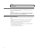
Contents Safety notices . . . . . . . . . . . . v Danger notices . . . . . . . . . . . . . v Caution notices . . . . . . . . . . . . . vi Handling static-sensitive devices . . . . . . . vi About this book . . . . . . . . . . . vii Who should read this book . . . Information available on the World Related information . . . . . How to send your comments . . . . Wide . . . . . . Web . . . . . . . . . . . . vii vii vii vii Understanding your NetVista Thin Client Express . . . . . . . . . . . . . . .
Trademarks . . . . . Electronic Emission Notices Federal Communications Statement . . . . . iv . . . . . . . . . . . . . . . . Commission (FCC) . . . . . . . . . 63 . 63 . 63 Glossary of abbreviations . . . . . . 65 Index . . . . . . . . . . . . . . .
Safety notices Safety notices contain information that is related to using the IBM® NetVista thin client in a safe manner. These notices can be in the form of a danger, caution, or attention notice. Danger notices The following danger notices call attention to situations that are potentially lethal or extremely hazardous. These notices pertain throughout this book.
DANGER To reduce the risk of electrical shock use only AC power sources approved by IBM. (RSFTD216) Caution notices A caution notice applies to a situation that is potentially hazardous to people because of some existing condition. CAUTION: The battery is a lithium battery. To avoid possible explosion, do not burn or charge the battery. Exchange only with the IBM-approved part. Discard the battery as instructed by local regulations.
About this book IBM NetVista N2800e Thin Client Express Reference (SA23-2808) provides information for the Type 8364 (Model Cxx) IBM NetVista N2800e Thin Client Express (hereafter referred to as workstation or thin client). This publication contains information on hardware setup, software configuration and update, hardware problem resolution, hardware upgrade options, parts replacement, and ordering.
v If you are mailing comments from a country other than the United States, you can give the form to the local IBM branch office or IBM representative for postage-paid mailing. v If you prefer to send comments by FAX, use either of the following telephone numbers: – United States and Canada: 1-800-937-3430 – Other countries: 1-507-253-5192 v If you prefer to send comments electronically, use the following network identification: – IBMMAIL, to IBMMAIL(USIB56RZ) – RCHCLERK@us.ibm.
Understanding your NetVista Thin Client Express The IBM NetVista N2800e Thin Client Express offers a fast and simple way to access applications on the following platforms: v Windows NT® Server 4.0 v Windows NT Server 4.0, Terminal Server Edition (TSE) v Windows NT Workstation 4.
2
Learning about the hardware This section provides detailed hardware information about the N2800e Thin Client Express — Hardware Type 8364 (Model Cxx), hereafter referred to as N2800e Thin Client Express. Standard hardware The standard N2800e Thin Client Express hardware includes the following: v 64 MB of SDRAM DIMM random access memory (RAM) (see “Appendix A. Replacing hardware parts” on page 41).
Communication hardware Your N2800e Thin Client Express includes an integrated Ethernet connection. For a 10 Megabit (Mb) line speed operation, you need a category 3 or higher Unshielded Twisted Pair (UTP) type of cable. For a 100 Mb line speed operation, you need a category 5 UTP type of cable. Refer to “Appendix G. Connector pin information” on page 59 for communication cable specifications.
expand the RAM of the N2800e by installing 32, 64, or 128 MB DIMMs. “Appendix B. Hardware maintenance procedures” on page 45 provides information on how to exchange memory. Refer to “Appendix A. Replacing hardware parts” on page 41 for detailed memory specifications and orderable N2800e Thin Client Express parts. Note: Use of the Netscape browser requires 64 MB of RAM.
6
Setting up the hardware Unpacking your hardware Unpack your hardware. Contact your reseller, or IBM, if you do not have these standard parts: 1 Thin client logic unit 2 Base 3 Mouse 4 Keyboard 5 Power cable Selecting the voltage for your location: Attention: You may damage the thin client if you do not select the correct voltage. 1. Locate the voltage switch A on the bottom of the thin client. 2.
Installing the support base Slide the base B onto the notched bottom of the thin client A until it latches securely. Connecting your hardware Read “Safety notices” on page v before continuing. 1. Connect the devices listed below to the appropriate ports: 1 USB devices 2 Network cable 3 Serial device 2 4 Serial device 1 5 Parallel devices 6 Monitor 7 Mouse 8 Keyboard 13 Headphones 14 Microphone 2. Tighten all device cable connections. 3.
Startup sequence This is a typical startup sequence of events for the NetVista Thin Client Express. If any of these events do not occur, see “Resolving hardware problems” on page 31. 1. The following devices show light-emitting diode (LED) indications: v Logic unit (system LED and network status LED) v Keyboard v Monitor1 v Any USB devices2 2. The following internal hardware components initialize: v Memory v L1 cache v Video memory v Keyboard controller 3.
10
Configuring the N2800e Thin Client Express Before you can use the N2800e Thin Client Express (also referred to as workstation) to access server applications, you need to configure your workstation. You can use the NSBoot Setup Utility (also referred to as Setup Utility) and the Thin Client Express Configuration Tool (or Configuration Tool) to configure workstations. Note: You do not need access to an external server to set up and configure the workstation.
The menu number A makes it easy to navigate through the Setup Utility. Menu numbers that begin with 2 are unique to the initial Setup Utility. The menu title B tells you which menu you are using. Use the arrow keys to select an option from the list of available options C . After you select an option, specify a value in the corresponding value field D . Certain fields allow you to select a value by using the Page Up and Page Down keys.
The Configuration Tool provides three Workstation Mode user interfaces: 1. A single application that starts automatically when you power on the workstation. This application fills the entire display screen. 2. One or more applications that start automatically when you power on the workstation. Note: The N2800e’s free memory determines how many applications you can run at one time.
14
Installing the Thin Client Service Utility and the Operations Utilities The Thin Client Express Service and Thin Client Manager Operations Utilities are management utilities that run on the following workstations or server platforms: v Windows NT Server 4.0 v Windows NT Server 4.0, Terminal Server Edition (TSE) v Windows NT Workstation 4.
Only the Operations Utility methods of updating in Table 1 on page 15 allow you to update multiple workstations at a time. The other methods of flash recovery in Table 1 on page 15 allow you to perform flash recovery to one workstation at a time. For more information on recovering or updating CompactFlash cards with the TCM Operations Utility, refer to IBM NetVista Thin Client Manager Operations Utility (SA23-2812). This information is available at the following URL: http://www.ibm.com/nc/pubs .
6. Click download NetVista Thin Client Express Service and Operations Utilities. 7. From the Downloads box, click the item that you want to download.
18
Managing your Thin Client Express remotely You can use the IBM NetVista Thin Client Manager Operations Utility to remotely manage your N2800e Thin Client Express. You can use the Thin Client Manager Operations Utility to manage both individual workstations, and workstation groups. Before you can use the Operations Utility to perform a task on a workstation, you need to perform the following tasks: v Install the Operations Utility on your computer.
20
PPP dialer for Thin Client Express workstations You can configure your Thin Client Express (hereafter referred to as workstation) for Point-to-Point Protocol (PPP) dial access. You can utilize this option if your workstation uses a modem to connect to a network. There are several prerequisites that you must meet before you can use PPP dialer.
b. Choose a display resolution setting and a display frequency setting. c. Configure the workstation Internet Protocol (IP) settings: 1) From the CompactFlash Boot - Configure IP settings menu, disable Dynamic Host Configuration Protocol (DHCP). 2) Verify that all IP values are 0.0.0.0. 3) From the CompactFlash Boot - Configure IP settings menu, enable Dial Access. 4) Press Enter. The workstation restarts, and the Configuration Tool appears on the display.
7. Type a userid and password in the appropriate fields. If you do not type a userid and password, the dialer prompts you for a userid and password each time that you connect to the network. Once you have completed the initial modem setting configurations for PPP dialer access, you can start the PPP dialer. It is necessary for you to successfully start the PPP dialer at this time to complete the configuration of your workstation for PPP dialer access.
b. Hold the keys down for several seconds until the Configuration Tool starts. Note: If you are unable to enter the Configuration Tool, the workstation may not have access to the Configuration Tool. Refer to IBM NetVista Thin Client Manager Operations Utility (SA23-2813) for more information about granting and denying access to the Configuration Tool. This information is available at the following URL: http://www.ibm.com/nc/pubs 2. Click Workstation Configuration. 3. Select Hardware—>Communications.
Altering the flash image of a workstation There are two methods that you can use to alter the flash image of a workstation: v “Performing a software update on a workstation” on page 25. v “Recovering the flash image of a workstation” on page 26. Notes: 1. When you perform a software update to the flash image of a workstation, you are only updating the software files. The workstatoin saves any configuration settings that you have made, during the software flash update process. 2.
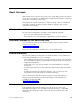
http://www.ibm.com/nc/pubs 2. If you have installed the Service Utility on a network server, ensure that the Service Utility services are running. If you have not installed the Service Utility on a network server, you can use another workstation as your flash update source. Continue with the next step. 3. From the Configuration Tool, click Remote Management / Software Update. 4. Click Configure Software Update Server Access. 5. Specify the IP address of the Service Utility server.
You need to specify the flash file that you want to use in the process, regardless of the method that you choose. See “Appendix E. Choosing a flash file” on page 55 for more information. Using one workstation to recover the flash image of another workstation You can use a peer workstation to perform a peer flash recovery on another workstation. The term peer flash recovery means that you use one workstation to recover the flash image of another workstation.
Do not exit the Configuration Tool at this time, as you will need to perform the procedure, “Disabling peer flash recovery on a workstation” on page 29 from this menu later. 7. Continue with the procedure, “Recovering the image on the peer-booted workstation”. Recovering the image on the peer-booted workstation The second step of peer flash recovery is recovering the image on the peer-booted workstation. The peer-booted workstation is the workstation whose flash image you are recovering.
Disabling peer flash recovery on a workstation The third step of peer flash recovery is to disable peer flash recovery on a workstation. Perform the following procedure from the workstation that you enabled to provide peer flash recovery: 1. From the Remote Management / Software Update menu, click Enable / Disable Peer Software Recovery.
13. Under Boot file server directory and file name, specify this directory and file name as the First option: /NS/flashbase/x86/kernel.2200 14. Under Boot file server protocol, set NFS to First. 15. Press F3 to save your settings and return to the Advanced Configuration menu. 16. Press F10 to reboot the workstation. 17. Specify the appropriate flash file, or BOM file, and press Enter to continue. For information on selecting the correct flash file, see “Appendix E. Choosing a flash file” on page 55.
Resolving hardware problems This section provides information on verifying and resolving hardware problems. If you cannot identify a hardware problem, you can request technical service and support by contacting IBM. You need to provide the machine type, model, and serial number of your NetVista thin client. You can obtain additional service and support information at the following URL: http://www.ibm.com/nc/support Notes: 1.
__ 2. Unplug the power cable from the electrical outlet. __ 3. Ensure that you properly connected all devices to the NetVista thin client. See “Connecting your hardware” on page 8 for more information. __ 4. Plug the NetVista thin client power cable into a properly grounded, working electrical outlet. __ 5. Power on the NetVista thin client. __ 6. Wait for the IBM NetVista thin client screen to appear on your monitor.
Table 4. Visible hardware failure (continued) Symptom What you should do The system LED does not light up when you 1. Verify that you plugged the power cable press the white power button to power on into a working electrical outlet. the NetVista thin client. 2. Verify that the power cable LED indicates a solid green color. 3. Reset power to the NetVista thin client by pressing the white power button. 4.
Table 4. Visible hardware failure (continued) Symptom v The mouse cursor stops moving; the mouse does not function at all. v The mouse cursor does not move smoothly. What you should do 1. Verify that you connected the mouse cable properly to the NetVista thin client keyboard. 2. If the mouse does not work, any of the following devices may be defective: v Mouse v Keyboard Substitute a properly working device for a defective device. Repeat the previous steps. See “Appendix A.
Table 5. Audio beep sequences Symptom The NetVista thin client emits a 1-3-1 beep sequence, and the system LED is flashing amber. What you should do Memory error 1. Check or replace the memory card. Refer to “Appendix B. Hardware maintenance procedures” on page 45 for instructions. 2. Verify that you properly connected the network cable to the NetVista thin client network connector. 3. Power on the NetVista thin client. 4.
Table 6. LED indications (continued) Symptom The system LED fails to function after power on. What you should do 1. Verify that you plugged the power cable into a working electrical outlet. 2. Press the white power button to reset power to the NetVista thin client. 3. If the system LED does not work, the power cable may be defective. Substitute a properly working power cable, and then repeat the steps.
If the NetVista thin client is not functioning properly, and an error code or text message appears on your screen, consult Table 7. Contact your technical support, reseller, or IBM, if these steps do not resolve the problem. Table 7. Error codes and text messages Symptom What you should do An error code or text message appears on the screen. 1. Record any error messages, audio beep sequences, or LED indications, and a description of the problem. 2. Perform any actions indicated within the error message.
Table 8. NSBxxxx error codes and text messages (continued) Error code Error message What you should do NSB21500 Audio failure. Replace the thin client logic unit (see “Appendix A. Replacing hardware parts” on page 41). Input, keyboard and mouse messages (NSB3xxxx, NSB31xxx, and NSB32xxx) NSB30500 No input device detected. Check the keyboard and mouse cable NS Boot will continue in connections. 10 seconds. NSB31500 Keyboard did not respond. Check the keyboard cable connection.
Table 8. NSBxxxx error codes and text messages (continued) Error code Error message What you should do NSB71509 DHCP option %d boot server name %s failed DNS. Verify that the DHCP server settings are correct. NSB71515 Missing DHCP option %d from server. Verify that the DHCP server settings are correct. NSB71525 Missing DHCP client IP address. Verify that the DHCP server settings are correct. NSB71535 Missing DHCP client directory and file name. Verify that the DHCP server settings are correct.
Table 8. NSBxxxx error codes and text messages (continued) Error code Error message What you should do NSB83539 Cannot PING boot server Verify your configuration settings in the NS x %s. Boot utility, and confirm the server configuration. NSB83549 Unable to open file. Confirm the server configuration. NSB83560 Boot file name or directory not valid. Verify your configuration settings in the NS Boot utility, and confirm the server configuration. NSB83579 Failed to boot after 1 attempt.
Appendix A. Replacing hardware parts You can order IBM replacement parts for the thin client. Contact IBM or your reseller to order warranty parts and non-warranty parts. IBM provides warranty service without charge for parts during the warranty period on an exchange basis only. To replace a logic unit, the customer must transfer features, such as memory DIMMs, CompactFlash cards, and any optional PCI adapter cards to the replacement assembly.
Replacing parts other than the N2800e CompactFlash card Use the following tables to determine the correct part number for replacement parts. Warranty service terms and conditions by country apply. Table 10.
Table 11.
Table 11. Detachable power cables (continued) Voltage Selection Plug Receptacle Country Part number 230V Denmark 13F9996 230V Israel 14F0086 230V Chile, Ethiopia, Italy 14F0068 230V Liechtenstein, Switzerland 14F0050 Returning hardware parts You may not need to return all defective items to IBM. Always check the replacement part packaging for any instructions regarding the return of defective parts.
Appendix B. Hardware maintenance procedures Removing the logic unit to install parts Read Safety notices, and “Handling static-sensitive devices” on page vi before continuing. 1. Turn off the power supply switch A . 2. Disconnect all cables from the thin client. 3. Hold the thin client cover assembly, lift latch B , and pull the logic unit C out. 4. Carefully lay the logic unit down with the internal components facing up. You are now ready to perform the installation procedures provided in this chapter.
Replacing a CompactFlash card Read “Caution notices” on page vi, and “Removing the logic unit to install parts” on page 45 before continuing. 1. Uninstall the N2800e thin client CompactFlash card by pulling it out of the connector B . 2. Match the grooves on the sides of the CompactFlash card that you are installing ( A ) to the inside of the connector B . 3. Install the CompactFlash card A into the connector B .
Exchanging the memory See “Resolving hardware problems” on page 31 to determine whether or not it is necessary to replace the logic unit, or any other parts. For information on ordering thin client hardware parts, refer to “Replacing parts other than the N2800e CompactFlash card” on page 42. Complete the procedure, “Removing the logic unit to install parts” on page 45 before performing the following Dual Inline Memory Module (DIMM) procedures: 1.
Removing the power supply: Notes: 1. Only IBM-authorized personnel should remove the power supply. 2. You will need a Phillips head screwdriver for the following procedure. 1. Complete the procedure, “Removing the logic unit to install parts” on page 45 before continuing. 2. Disconnect the power supply connector A from the logic board. Pinch the top of the power supply connector as you disconnect it from the logic board. This releases the power supply connector latch. 3.
Installing the power supply: 1. Carefully install the power supply into the logic unit so that the power supply fan assembly faces the front of the logic unit. 2. Slide the power supply toward the back of the logic unit until it stops. 3. Make sure that the power supply is seated correctly, and firmly into the logic unit. 4. Secure the power supply with the three Phillips head screws A removed during the power supply removal procedure. 5.
50
Appendix C. Setting the thin client voltage for your location Selecting the voltage for your location: Note: All N2800e thin clients are preset to the 230V setting when manufactured. 1. Power off the N2800e thin client. 2. Remove the base from the N2800e thin client. 3. Locate the voltage selector switch A . 4. Use a pen, or similar object, to slide the switch to the correct setting for your location (see Voltage selection in Table 11 on page 42). 5. Slide the base back on to the N2800e thin client. 6.
52
Appendix D. Recovering the boot block image This section provides instructions that should be followed only under the direction of the IBM Service and Support team. Use these instructions only if you encountered a power interruption during a software update. Read “Safety notices” on page v before you continue with these instructions. Creating a recovery CompactFlash card: This procedure creates a copy of the thin client firmware (hereafter referred to as flash image).
Recovering the flash image You need a CompactFlash card with an N2800e (machine type 8364) flash image to complete this procedure. See “Creating a recovery CompactFlash card” on page 53 to create a recovery CompactFlash card. 1. Complete the procedure, “Removing the logic unit to install parts” on page 45 before continuing. 2. Insert the CompactFlash card into the CompactFlash connector. 3. Move the jumpers into configuration 2 . Note: All systems ship with jumpers installed in configuration 1 . 4.
Appendix E. Choosing a flash file Regardless of which method you use to update the flash image of a workstation, you may need to specify the flash file to use. These files, which are sometimes called Bill of Material (BOM) files, contain a list of files that make up a flash image. When reflashing your flash card, you must specify which image you want. Note: The first three images listed below include Netscape browser and PPP Dialer support. Table 12.
56
Appendix F. Monitor specifications A basic video graphics adapter (VGA) class monitor that meets the VESA standards of refresh rate and resolution can function with the thin client. The thin client supports VESA Display Power Management Signaling (DPMS) and VESA Display Data Channel (DDC2B). A monitor that is attached to the thin client does not require either standard. You configure the resolution in each case at the client operating system (OS) level.
58
Appendix G. Connector pin information The following tables define the connector pins that are used with the N2800e thin client. Table 14.
Table 16. Parallel Connector (continued) Pin Signal 16 17 18 - 25 INIT SELECTIN Ground Table 17. RJ-45 Twisted Pair Connector Pin Name 1 2 3 4/5 6 7/8 TPOP TPON TPIP Not used TPIN Not used Table 18. USB connector Pin # Direction 1 2 3 4 5 6 7 8 Power Bidir Bidir Power Power Bidir Bidir Power Table 19. Power supply connector Pin # Voltage+5V dc 1 2 3 4 5 6 7 8 9 10 11 12 13 14 60 +5V dc +5V dc +3.3V dc +3.3V dc +3.
Notices This information has been developed for products and services that are offered in the U.S.A. IBM may not offer the products, services, or features that are discussed in this document in other countries. Consult your local IBM representative for information on the products and services currently available in your area. Any reference to an IBM product, program, or service is not intended to state or imply that only that IBM product, program, or service may be used.
IBM has not tested those products and cannot confirm the accuracy of performance, compatibility, or any other claims related to non-IBM products. Questions on the capabilities of non-IBM products should be addressed to the suppliers of those products. All statements regarding IBM’s future direction or intent are subject to change or withdrawal without notice, and represent goals and objectives only. If you are viewing this information softcopy, the photographs and color illustrations may not appear.
Trademarks The following terms are trademarks of International Business Machines Corporation in the United States, or other countries, or both: AS/400 IBM NetVista Network Station S/390 Wake on LAN Java™, and all Java-based trademarks, and logos are trademarks, or registered trademarks of Sun Microsystems, Inc. in the United States, other countries, or both. Microsoft®, Windows, Windows NT, and the Windows logo are trademarks of Microsoft Corporation in the United States, other countries, or both.
International Business Machines Corporation New Orchard Road Armonk, NY 10504 Telephone: 1-919-543-2193 Industry Canada Compliance Statement This Class B digital apparatus meets the requirements of the Canadian Interference-Causing Equipment Regulations. Avis de conformité à la réglementation d’Industrie Canada Cet appareil numérique de la classe B respecte toutes les exigences du Réglement sur le matériel brouilleur du Canada.
Glossary of abbreviations A H AC. Alternating Current HTTP. Hypertext Transfer Protocol ARP. Address Resolution Protocol Hz. Hertz or cycles per second B I BOM. Bill of Material IBM. International Business Machines BOOTP. Bootstrap Protocol ICA. Independent Computing Architecture C ICMP. Internet Control Message Protocol ISO. International Organization for Standardization CD. Compact Disc ID. Identification CRU. Customer-Replaceable Unit IEEE.
NSBXXXXX. Network Station Boot message with identification number (XXXXX) V NSM. Network Station Manager V. Volts NVRAM. Nonvolatile Random Access Memory (also referred to as local settings) VESA. Video Electronics Standards Association O VM. Virtual Machine OS. Operating System P PC. Personal Computer POST. Power On Self Test PPP. Point-to-Point Protocol R RAM. Random Access Memory RAP. Remote Authentication Protocol RIF. Routing Information Field RFS. Remote File System S SDRAM.
Index A access configuring initial modem settings for PPP dialer 22 prerequisites for using PPP 21 B BOM file, choosing a 55 boot block image 53 recovering 53 C CD installing the utilities from the NetVista Thin Client Utilities CD 16 CompactFlash card, replacing the N2800e Thin Client Express 41 configuration preparing the workstation for PPP dialer 21 Configuration Tool 12 accessing 13 using the configuration tool to perform a software update on a workstation 25 configuring N2800e 11 using the Configura
N2800e (continued) understanding 1 NC dialer window, learning about the 23 NetVista Thin Client website 16 network cables 4 O Operations Utility installing 15 using TCM to perform a software update on a workstation 26 using TCM to recover the flash image of a workstation 30 ordering replacement parts 42 P parameters maintaining and reconfiguring PPP dialer parameters 23 peer-booted workstation recovering the image 28 peer flash recovery 27 disabling 29 enabling 27 pin information connector 59 power consum
Readers’ Comments — We’d Like to Hear from You NetVista™ N2800e Thin Client Express Reference September 2000 To view or print the latest update, go to http://www.ibm.com/nc/pubs Publication No.
SA23-2808-00 ___________________________________________________________________________________________________ Readers’ Comments — We’d Like to Hear from You Cut or Fold Along Line _ _ _ _ _ _ _Fold _ _ _and _ _ _Tape _ _ _ _ _ _ _ _ _ _ _ _ _ _ _ _ _ _ _ _ _ _ _ _ _ _ _Please _ _ _ _ do _ _ not _ _ _staple _ _ _ _ _ _ _ _ _ _ _ _ _ _ _ _ _ _ _ _ _ _ _ _ _ _ _ _Fold _ _ _and _ _ Tape ______ PLACE POSTAGE STAMP HERE IBM CORPORATION ATTN DEPT 542 IDCLERK 3605 Highway 52 N ROCHESTER MN 55901-7829
SA23-2808-00