LV-671 Mini-ITX Motherboard User’s Manual Edition: 1.
LV-671 User’s Manual 2
LV-671 User’s Manual 3
LV-671 User’s Manual Copyright Copyright© 2003 - 2004. All rights reserved. This document is copyrighted and all rights are reserved. The information in this document is subject to change without prior notice to make improvements to the products. This document contains proprietary information and protected by copyright. No part of this document may be reproduced, copied, or translated in any form or any means without prior written permission of the manufacturer.
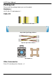
LV-671 User’s Manual Packing List Please check the package before you use this product Hardware: LV-671 Mini-ITX motherboard x 1 Cable Kit: 40-pin ATA100 IDE Cable x 1 26-pin Slim Type Floppy Cable x 1 4-pin to 4-pin Power Cable x 1 CPU Cooler x 1 Other Accessories Driver CD (Including User’s Manual ) x 1 5
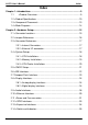
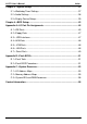
LV-671 User’s Manual Index Index Chapter 1 ..................................................................................... 9 1.1 .......................................................................... 9 1.2 ......................................................................... 10 1.3 ...................................................................... 13 1.4 .......................................
LV-671 User’s Manual Index Chapter 3 ................................................................................ 37 3.1 ..................................................................... 37 3.2
LV-671 User’s Manual (This Page is Left for Blank) 8
LV-671 User’s Manual Introduction Chapter 1 1.1 LV-671 is an all-in-one industrial compact Pentium-M level motherboard based on Mini-ITX form factor at 170 x 170 mm of dimension. Based on Intel 855GME and ICH4 chipset, LV-671 offers the compact, embedded, value and high performance solution with Intel Pentium-M CPU, 400MHz/533MHz of FSB, 1GBytes DDR200/266/333 SDRAM with ECC, Intel 855GME GMCH built-in Intel Extreme Graphics 2, Intel PRO/1000+ LAN, Hi-Speed USB 2.0, 5.
LV-671 User’s Manual 1.2 General Specification Form Factor CPU Memory Chipset BIOS Green Function Watchdog Timer Real Time Clock Enhanced IDE Mini-ITX motherboard at 170 x 170 mm (L x W) Package: 478 pin PGA/ 479 pin BGA L2 Cache: 512KB/1MB/2MB FSB: 400MHz/533MHz ( The Intel® Celeron® M Processor 4xx series have been designed to work with the Mobile Intel® 945 Express Chipset Family only .
LV-671 User’s Manual Frame Buffer Introduction Intel DVMT (Dynamic Video Memory Technology) 2.0 up to 64Mbytes shared with system* CRT and LCD monitors for analog display 24-bit single/dual channel LCD panel for digital display External DB15 female connector on rear I/O panel Internal 40-pin LVDS connector Display Type Connector *Under Windows 98/ME/2000/XP/Server2003 or Linux kernel 2.
LV-671 User’s Manual Power and Environment Power Requirement Input Voltage Range Input Current Dimension Temperature One external 19V/12V (auto switching) DC Adapter connector on rear panel 4-pin onboard 12V P4 4-pin power connector (Two power resources selectable for each) 11V ~ 13V for 12V power supply 16V ~ 20V for 19V power supply 12V/60W (with one 5.25” CDROM and 3.5” HDD) 19V/60W (with one 5.25” CDROM and 3.
LV-671 User’s Manual Introduction 1.3 1 x 184-pin DDR266/333 DIMM up to 1GB Intel ICH4 (Southbridge) Intel 855GME (Northbridge) Socket479 For 478-pin PGA Pentium M/Celeron M Onboard DC to DC inverter Intel 82540EM Gigabit LAN REALTEK ALC655 5.
LV-671 User’s Manual 1.4 Intel Pentium M processor with FC-PGA2/FC-BGA2 400MHz/533MHz FSB CRT DDR266/333 LVDS LCD DIMM Up to 1GB AGP 4x Mini-AGP 1 x 184-pin DVO B/C 855GME PCI Bus ATAPI Devices UltraATA100 USB Devices 33MHz USB2.
LV-671 User’s Manual Hardware Setup Chapter 2 This chapter contains the information for installation of hardware. The install procedure includes jumper settings, CPU and memory installation, fan, I/O and panel connections. 2.
LV-671 User’s Manual Hardware Setup 2.
LV-671 User’s Manual Hardware Setup 2.3 2.3.1 Connector CPU DIMM IDE1 IDE2 FDD CN_USB1 CN_USB2 CN_IR CN_12V CN_BPWR CN_SPWR JFRNT CPUFAN SYSFAN CN_AUDIO CDIN CN_WOL CN_LVDS CN_INV CN_DIO CN_LAN2 CN_2ND_IO CF PCMCIA Function MicroPGA479 CPU Socket 184-pin DIMM Socket 40-pin Primary IDE Port 44-pin Secondary IDE Port 26-pin slim type FDD Port 10-pin 3rd / 4th Hi-Speed USB 2.0 Port 10-pin 5th / 6th Hi-Speed USB 2.
LV-671 User’s Manual Hardware Setup 2.4 2.4.1 The board supports Intel Pentium M/ Celeron M processor with 400MHz/533MHz of front side bus, 512KB/1MB/2MB of L2 cache, there are two package type of the processor, 478-pin PGA for socket479 onboard version; 479-pin BGA for embedded processor version. Please check installation steps below for onboard socket479 version.
LV-671 User’s Manual Hardware Setup 2.4.2 The board supports one 184-pin DDR266/333 (PC2100/PC2700) SDRAM up to 1GB of capacity, and supports ECC (Error Correcting Code), unbufferred memory modules. DIMM 104-pin 80-pin Please check the pin number to match the socket side well before installing memory module.
LV-671 User’s Manual Hardware Setup 2.4.3 The board accessories come with one CPU cooler, the cooler’s specification is listed below, please check the installation steps before you start. Notice: Installing the cooler improperly may cause the system unstable, if you face system rebooting or other issue, please check this point. Cooler Specification: Rated Voltage 12V Consumption Max 0.12Amp Sound Level Max 27dB Rated Speed 5000rpm Air Flow Max 4.
LV-671 User’s Manual Hardware Setup 2.5 The board’s data of CMOS can be setting in BIOS. If the board refuses to boot due to inappropriate CMOS settings, here is how to proceed to clear (reset) the CMOS to its default values.
LV-671 User’s Manual Hardware Setup 2.6 The board supports two IDE interface up to 4 ATAPI devices, base on Intel ICH4, the IDE interface supports ATA66/100 ATAPI drives. The IDE1 supports +5V on pin-20 for DOM (Disk on Module), the jumper JDOM can let you select enable/disable this support. Jumper: JDOM Type: onboard 3-pin header JDOM Mode ON IDE1 pin-20 5V power supply enable OFF No 5V power supply on IDE1 pin-20 Default setting 39 1 40 2 JDOM IDE1 (40-pin pitch=2.
LV-671 User’s Manual Hardware Setup 2.7 Compact Flash Interface The board supports Compact Flash Type I socket for storage flash disk only, the jumper JCFSEL can let you to setup the flash card operate on secondary master or slave mode.
LV-671 User’s Manual Hardware Setup 2.8 2.8.1 The board is integrated with Intel 855GM GMCH chipset built-in Intel Extreme Graphics 2 with 266 MHz VGA core, 256-bit 3D engine and Intel Dynamic Video Memory up to 64MBytes shared with system memory. The CRT / analog VGA interface includes one external DB15 female connector on bracket on board. VGA 2.8.2 The board’s digital video interface provides LVDS flat panel support.
LV-671 User’s Manual Hardware Setup Connector: CN_INV Type: 5-pin LVDS Power Header Pin 1 2 3 4 5 Description +12V GND GND GND ENABKL Connector: JVLCD Type: 3-pin Power select Header Pin 1 2 3 Description VCC LCDVCC VCC3 Connector: CN_LVDS Type: onboard 40-pin connector for LVDS connector Connector model: HIROSE DF13-40DP-1.
LV-671 User’s Manual Hardware Setup LCD installing guide: 1. Prepare a panel, inverter and LV-671. 2. 3. Please check the datasheet of the panel to see the voltage of the panel, and set the jumper JVLCD to +5V or +3.3V. Prepare a LVDS type LCD cable Board side Panel side For sample illustrator only 4. Connect all the devices well.
LV-671 User’s Manual Hardware Setup After setup the devices well, you need to select the LCD panel type in the BIOS. The panel type mapping is list below: BIOS panel type selection form For 18-bit color For 24-bit color NO. Output format NO.
LV-671 User’s Manual Hardware Setup 2.9
LV-671 User’s Manual Hardware Setup Connector: CN_AUDIO Type: 10-pin (2 x 5) 2.
LV-671 User’s Manual Hardware Setup 2.10 The board integrates with Intel 82540EM Gigabit controller at the type of 10Base-T/100Base-TX/1000Base-T auto-switching Ethernet with full duplex and IEEE 802.3U compliant. The LAN function comes with a RJ45 jack on the rear I/O panel. The CN_WOL is for the Wake-Up-On-LAN function link with PCI LAN Card.
LV-671 User’s Manual Hardware Setup 2.11 The board comes with a 4-pin Mini-DIN power connector for DC 12V/19V auto-switching input, it also has one 4-pin P4 additional use power connector for internal power supply, you can choose one pf them to meet your application. The board has two power connectors for 5V/12V output to powering your ATAPI drives directly, and it has two fan connectors for CPU and system cooling.
LV-671 User’s Manual Hardware Setup Connector: CN_12V Type: 4-pin standard Pentium 4 +12V power connector Pin Description Pin Description 1 +12V 2 +12V 3 Ground 4 Ground Connector: DC_IN Type: 4-pin DC power connector Pin Description 1 +12V 3 +12V Connector: CPUFAN, SYSFAN Type: 3-pin fan wafer connector Pin Description Pin 1 Ground 2 Pin 2 4 Description Ground Ground Description +12V Pin 3 Description Fan Control Connector: CN_BPWR Type: 4-pin P-type connector for +5V/+12V output Pin Description Pi
LV-671 User’s Manual Hardware Setup 2.12 The board offers 16-bit digital I/O to customize its configuration to your control needs. For example, you may configure the digital I/O to control the opening and closing of the cash drawer or to sense the warning signal from a tripped UPS.
LV-671 User’s Manual Hardware Setup 2.13 The board comes with one slim type PCI slot and one optional Mini-AGP or Mini-PCI interface. The slim PCI slot supports up to 2 PCI devices through an optional riser card. For Mini-PCI interface, you can obtain a wireless LAN card for potable system. For Mini-AGP interface, you can obtain an extended graphic card to improve the onboard graphics performance.
LV-671 User’s Manual Hardware Setup 2.14 Connector: JFRNT Type: onboard 14-pin (2 x 7) 2.
LV-671 User’s Manual (This Page is Left for Blank) 36
LV-671 User’s Manual System Setup Chapter 3 3.1 The watchdog timer makes the system auto-reset while it stops to work for a period. The integrated watchdog timer can be setup as system reset mode by program.
LV-671 User’s Manual System Setup 3.2
LV-671 User’s Manual System Setup 3.3 This chapter shows you how to setup the display device under Windows OS. Before you using your display device: 1. Check your software Before you can use the display device properly, please install the VGA driver. 2. Check your hardware Please setup the display device properly before you boot up the system. For configure your Display device, please follow the instructions below: 1. Please lunch Display Properties.
LV-671 User’s Manual System Setup For advanced display settings, please click Advanced… button and choose Intel(R) Extreme Graphics. Please click Graphics Properties button to enter the advanced setup.
LV-671 User’s Manual System Setup While you entering the Graphics Properties, you will see the options below: This option can let you configure the CRT monitors for Colors, Screen Area (Resolution) and Refresh Rate. This option can let you configure the LCD panel for Colors, Screen Area (Resolution) and Full Screen option.
LV-671 User’s Manual System Setup This option can let you configure the Dual Display for clone mode (same display on two devices) This option can let you configure the Dual Display for Extended Desktop mode 42 Display Device Setup
LV-671 User’s Manual BIOS Setup Chapter 4 The single board computer uses the Award BIOS for the system configuration. The Award BIOS in the single board computer is a customized version of the industrial standard BIOS for IBM PC AT-compatible computers. It supports Intel x86 and compatible CPU architecture based processors and computers. The BIOS provides critical low-level support for the system central processing, memory and I/O sub-systems.
LV-671 User’s Manual (This Page is Left for Blank) 44
LV-671 User’s Manual I/O Port Pin Assignment Appendix A A.
LV-671 User’s Manual I/O Port Pin Assignment Connector: IDE2 2 44 1 43 Type: 44-pin (22 x 2) box header Pin 1 3 5 7 9 11 13 15 17 19 21 23 25 27 29 31 33 35 37 39 41 43 46 Description Reset D7 D6 D5 D4 D3 D2 D1 D0 Ground REQ IOW-/STOP IOR-/HDMARDY IORDY/DDMARDY DACKIRQ A1 A0 CS1 IDEACTVCC Ground Pin 2 4 6 8 10 12 14 16 18 20 22 24 26 28 30 32 34 36 38 40 42 44 Description Ground D8 D9 D10 D11 D12 D13 D14 D15 N/C Ground Ground Ground IDESEL Ground N/C CBLID A2 CS3 Ground VCC Ground IDE Port
LV-671 User’s Manual I/O Port Pin Assignment A.2 Connector: FDD Type: 26-pin connector Pin Description 1 VCC 3 VCC 5 VCC 7 DRV1 9 MTR1 11 RPM 13 N/C 15 Ground 17 Ground 19 N/C 21 N/C 23 Ground 25 Ground Pin 2 4 6 8 10 12 14 16 18 20 22 24 26 Description INDEX DRV0 DSKCHG N/C MTR0 DIR STEP WRITE DATA WRITE GATE TRACK 0 WRPTR RDATASEL A.
LV-671 User’s Manual I/O Port Pin Assignment A.4 5 Connector: CN_IR Type: 5-pin header for SIR Ports Pin Description 1 VCC 2 N/C 3 IRRX 4 Ground 5 IRTX 1 6 A.5 < VGA Port > 11 1 2 3 4 5 Connector: VGA Type: 15-pin D-sub female connector on bracket Pin Description Pin Description 1 RED 6 Ground 2 GREEN 7 Ground 3 BLUE 8 Ground 4 N/C 9 LVGA5V 5 Ground 10 Ground 12 13 14 15 10 Pin 11 12 13 14 15 Description N/C 5VCDA HSYNC VSYNC 5VCLK A.
LV-671 User’s Manual I/O Port Pin Assignment A.7 < Serial Port > 5 Connector: COM1 Type: 9-pin D-sub male connector on bracket Pin 1 2 3 4 5 Description MDCD1MSIN1MSO1MDTR1Ground Pin 6 7 8 9 1 9 Description MDSR1MRTS1MCTS1MRI1- 5 Connector: COM2 Type: 9-pin D-sub male connector on bracket Pin 1 2 3 4 5 Description MDCD2MSIN2MSO2MDTR2Ground Pin 6 7 8 9 6 9 1 6 Description MDSR2MRTS2MCTS2MRI2- Output Voltage: +/- 9V.
LV-671 User’s Manual (This Page is Left for Blank) 50
LV-671 User’s Manual Flash BIOS Appendix B B.1 The board is based on Award BIOS and can be updated easily by the BIOS auto flash tool. You can download the tool online at the address below: http://www.phoenix.com/en/home/ http://www.commell.com.tw/Support/Support_SBC.htm File name of the tool is “awdflash.exe”, it’s the utility that can write the data into the BIOS flash ship and update the BIOS. B.2 1. Please make a bootable floppy disk. 2. Get the last .
LV-671 User’s Manual (This Page is Left for Blank) 52
LV-671 User’s Manual System Resource Appendix C C.
LV-671 User’s Manual 54 System Resource x03F8 - x03FF Communication Port (COM1) x0400 - x04BF Motherboard Resource x04D0 - x04D1 Motherboard Resource x0500 - x051F Intel(R) 82801DB/DBM SMBus Controller - 24C3 x0778 - x077B Printer Port (LPT1) x0A78 - x0A7B Motherboard Resource x0B78 - x0B7B Motherboard Resource x0BBC - x0BBF Motherboard Resource x0CF8 - x0CFF PCI Bus x0E78 - x0E7B Motherboard Resource x0F78 - x0F7B Motherboard Resource x0FBC - x0FBF Motherboard Resource xA000 - xB
LV-671 User’s Manual System Resource C.
LV-671 User’s Manual System Resource C.3 C3.
LV-671 User’s Manual System Resource C3.
LV-671 User’s Manual Contact Information Any advice or comment about our products and service, or anything we can help you please don’t hesitate to contact with us. We will do our best to support you for your products, projects and business Taiwan Commate Computer Inc. Address 8F, No. 94, Sec. 1, Shin Tai Wu Rd., Shi Chih Taipei Hsien, Taiwan TEL +886-2-26963909 FAX +886-2-26963911 http://www.commell.com.tw Website TU UT info@commell.com.tw (General Information) E-Mail TU UT tech@commell.com.