Hardware Maintenance Manual for Service Level A For Micro Tower Models Machine Type 2169 European Market Only i
Note Before using this information and the product it supports, be sure to read the general information under “Notices“ on page 1.
Contents Notices ................................................................................ 4 Voltage Supply Switch Settings .......................................... 3 Safety Information................................................................ 4 Laser Compliance Statement.............................................. 33 Trademarks.......................................................................... 34 Preface................................................................................
Repairing Information ....................................................... 110 Removals and Replacements of machine type ................. 111 Identifying the Parts of the System Unit.............................. 112 Top Cover ............................................................................ 114 Adapter Cards ............................................................... 115 Diskette Drive ................................................................ 117 CD-ROM Drive .....................
Notices References in this publication to IBM products, programs, or services do not imply that IBM intends to make these available in all countries in which IBM operates. Any reference to an IBM product, program, or service is not intended to state or imply that only IBM’s product, program, or service may be used.
Safety Information DANGER To avoid a shock hazard, do not connect or disconnect any cables or perform installation, maintenance, or reconfiguration of this product during an electrical storm. To avoid shock hazard: q The power cord must be connected to a properly wired and earthed receptacle. q Any equipment to which this product will be attached must also be connected to properly wired receptacles.
To Connect 1. Turn Everything OFF. To Disconnect 1. Turn Everything OFF. 2. First, attach all cables to devices. 2. First, remove power cord(s) from outlet 3. Attach signal cables to receptacles. 3. Remove signal cables from receptacles. 4. Attach power cord(s) to outlet. 4. Remove all cables from devices. 5. Turn device ON NOTE: In the U.K., by law, the telephone cable must be connected after the power cord. When disconnecting, the power cord must be disconnected after the telephone line cable.
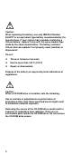
Caution: When replacing the battery, use only IBM Part Number 36L9077 or an equivalent type battery recommended by the manufacturer. If your system has a module containing a lithium battery, replace it only with the same module type made by the same manufacturer. The battery contains lithium and can explode if not properly used, handled, or disposed of.
DANGER Some CD-ROM drives contain an embedded Class 3A or Class 3B laser diode. Note the following. Laser radiation when open. Do not stare into the beam, do not view directly with optical instruments, and avoid direct exposure to the beam. ≥ 32 Kg ≥ 55Kg (70.5 (121.2 lbs) lbs) Caution: Use safe lifting practices when lifting your machine. Caution: Electrical current from power, telephone, and communication cables can be hazardous.
PERIGO Para evitar choques elétricos, não conecte ou desconecte nenhum cabo, nem efetue instalação, manutenção ou reconfiguração deste produto durante uma tempestade com raios. Para evitar choques elétricos: q q O cabo de alimentação deve ser conectado a um receptáculo corretamente instalado e aterrado. Todos os equipamentos aos quais este produto será conectado devem também ser conectados a receptáculos corretamente instalados.
Para Conectar Para Desconectar 1. DESLIGUE tudo. 1. DESLIGUE tudo. 2. Conecte primeiro todos os cabos nos dispositivos. 2. Remova primeiro o(s) cabo(s) de alimentação das tomadas. 3. Conecte os cabos de sinal nos receptáculos. 4. Conecte o(s) cabo(s) de alimentação nas tomadas. 3. Remova os cabos de sinal dos receptáculos. 4. Remova todos os cabos dos dispositivos. 5. LIGUE o dispositivo.
cuidado: Ao substituir a bateria, utilize apenas o Número de Peça IBM 33F8354 ou um tipo de bateria equivalente recomendado pelo fabricante. Se seu sistema possuir um módulo com uma bateria de lítio, substitua-o apenas pelo mesmo tipo de módulo, produzido pelo mesmo fabricante. A bateria contém lítio e pode explodir se não for utilizada, manuseada e descartada de forma adequada. Não: q Jogue ou coloque na água ¨ Aqueça a mais de 100°C (212°F) q Conserte nem desmonte.
PERIGO Algumas unidades de CD-ROM contém um diodo de laser da Classe 3A ou da Classe 3B. Observe o seguinte. Radiação de laser quando aberto. Não olhe diretamente para o feixe de laser, não olhe diretamente com instrumentos óticos, e evite exposição direta ao raio. ≥ 32 Kg (70,5 lbs) ≥ 55Kg (121,2 lbs) cuidado: Utilize práticas seguras para levantamento de peso ao levantar sua máquina. cuidado: A corrente elétrica proveniente de cabos de alimentação, de telefone e de comunicação é perigosa.
12
13
14
15
16
DANGER Pour éviter tout risque de choc électrique, ne manipulez aucun câble et n'effectuez aucune opération d'installation, d'entretien ou de reconfiguration de ce produit au cours d'un orage. Pour éviter tout risque de choc électrique : q Les cordons d'alimentation du présent produit et de tous les appareils qui lui sont connectés doivent être branchés sur des socles de prise de courant correctement câblés et mis à la terre.
attention: Remplacez la pile usagée par une pile de référence identique exclusivement - voir la référence IBM - ou par une pile équivalente recommandée par le fabricant. Si votre système est doté d'un module contenant une pile au lithium, vous devez le remplacer uniquement par un module identique, produit par le même fabricant. La pile contient du lithium et présente donc un risque d'explosion en cas de mauvaise manipulation ou utilisation. q Ne la jetez pas à l'eau.
DANGER Certaines unités de CD-ROM contiennent une diode laser de classe 3A ou 3B. Prenez connaissance des informations suivantes : Rayonnement laser lorsque le carter est ouvert. Évitez de regarder fixement le faisceau ou de l'observer à l'aide d'instruments optiques. Évitez une exposition directe au rayon. ≥ 32 Kg ≥ 55Kg attention: Ce produit pèse un poids considérable. Faites-vous aider pour le soulever.
Le courant électrique circulant dans les câbles de communication et les cordons téléphoniques et d'alimentation peut être dangereux. Pour votre sécurité et celle de l'équipement, avant de retirer les carters, mettez celui-ci hors tension et déconnectez ses cordons d'alimentation, ainsi que les câbles qui le relient aux réseaux, aux systèmes de télécommunication et aux modems (sauf instruction contraire mentionnée dans les procédures d'installation et de configuration).
Kabel anschließen Kabel lösen 1. Alle Geräte ausschalten und Netzstecker ziehen. 1. Alle Geräte ausschalten. 2. Zuerst alle Kabel an Einheiten anschließen. 2. Zuerst Netzstecker von Steckdose lösen. 3. Signalkabel an Anschlußbuchsen anschließen. 3. Signalkabel von Anschlußbuchsen lösen. 4. Netzstecker an Steckdose anschließen. 4. Alle Kabel von Einheiten lösen. 5. Gerät einschalten.
achtung: Wenn ein CD-ROM-Laufwerk installiert ist, beachten Sie folgendes. Steuer- und Einstellelemente sowie Verfahren nur entsprechend den Anweisungen im vorliegenden Handbuch einsetzen. Andernfalls kann gefährliche Laserstrahlung auftreten. Das Entfernen der Abdeckungen des CD-ROM-Laufwerks kann zu gefährlicher Laserstrahlung führen. Es befinden sich keine Teile innerhalb des CD-ROM-Laufwerks, die vom Benutzer gewartet werden müssen. Die Verkleidung des CD-ROM-Laufwerks nicht öffnen.
VORSICHT Manche CD-ROM-Laufwerke enthalten eine eingebaute Laserdiode der Klasse 3A oder 3B. Die nachfolgend aufgeführten Punkte beachten. Laserstrahlung bei geöffneter Tür. Niemals direkt in den Laserstrahl sehen, nicht direkt mit optischen Instrumenten betrachten und den Strahlungsbereich meiden. ≥ 32 Kg ≥ 55Kg achtung: Beim Anheben der Maschine die vorgeschriebenen Sicherheitsbestimmungen beachten. achtung: An Netz-, Telefon- und Datenleitungen können gefährliche elektrische Spannungen anliegen.
PERICOLO Per evitare il pericolo di scosse elettriche durante i temporali, non collegare o scollegare cavi, non effettuare l'installazione, la manutenzione o la riconfigurazione di questo prodotto. Per evitare il pericolo di scosse elettriche: q collegare il cavo di alimentazione ad una presa elettrica correttamente cablata e munita di terra di sicurezza; q collegare qualsiasi apparecchiatura collegata a questo prodotto ad una presa elettrica correttamente cablata e munita di terra di sicurezza.
ATTENZIONE: Quando si sostituisce la batteria, utilizzare solo una batteria IBM o batterie dello stesso tipo o di tipo equivalente consigliate dal produttore. Se il sistema di cui si dispone è provvisto di un modulo contenente una batteria al litio, sostituire tale batteria solo con un tipo di modulo uguale a quello fornito dal produttore. La batteria contiene litio e può esplodere se utilizzata, maneggiata o smaltita impropriamente.
PERICOLO Alcune unità CD-ROM contengono all'interno un diodo laser di Classe 3A o Classe 3B. Prestare attenzione a quanto segue: Aprendo l'unità vengono emesse radiazioni laser. Non fissare il fascio, non guardarlo direttamente con strumenti ottici ed evitare l'esposizione diretta al fascio. ≥ 32 Kg ≥ 55Kg ATTENZIONE: Durante il sollevamento della macchina seguire delle norme di di sicurezza. ATTENZIONE: La corrente circolante nei cavi di alimentazione, del telefono e di segnale è pericolosa.
27
28
29
PELIGRO Para evitar una posible descarga eléctrica, no conecte ni desconecte los cables ni lleve a cabo ninguna operación de instalación, de mantenimiento o de reconfiguración de este producto durante una tormenta eléctrica. Para evitar una posible descarga: q El cable de alimentación debe conectarse a un receptáculo con una instalación eléctrica correcta y con toma de tierra.
caution: Al cambiar la batería, utilice únicamente la batería IBM Número de pieza 33F8354 o un tipo de batería equivalente recomendado por el fabricante. Si el sistema tiene un módulo que contiene una batería de litio, sustitúyalo únicamente por el mismo tipo de módulo del mismo fabricante. La batería contiene litio y puede explotar si no se utiliza, manipula o desecha correctamente. Lo que no debe hacer • • • Tirar o sumergir el producto en agua. Exponer el producto a una temperatura superior a 100°C.
PELIGRO Algunas unidades de CD-ROM tienen incorporado un diodo de láser de Clase 3A o de Clase 3B Tenga en cuenta la siguiente información. Cuando la unidad está abierta se generan emisiones de rayos láser. No dirija la mirada al haz, no lo observe directamente con instrumentos ópticos y evite la exposición directa. ≥ 32 Kg ≥ 55Kg caution: Alce la máquina con cuidado; el sobrepeso podría causar alguna lesión.
Laser Compliance Statement The CD/DVD-ROM drive in the computer is a laser product. The CD/DVD-ROM drive's classification label (sample shown below) is located on the drive. CLASS 1 LASER PRODUCT APPAREIL A LASER CLASSE 1 LASER KLASSE 1 LUOKAN 1 LASERLAITE PRODUIT LASER CATEGORIE 1 The CD/DVD-ROM drive is certified in the U.S. to conform to the requirements of the Department of Health and Human Services 21 Code of Federal Regulations (DHHS 21 CFR) Subchapter J for Class 1 laser products.
Trademarks The following are trademarks of the IBM Corporation in the United States or other countries or both: Operating System/2 AT HelpCenter IBM OS/2 Personal System/2 PS/1 PS/2 Intel, Pentium, MMX, EtherExpress, and LANDesk are trademarks or registered trademarks of Intel Corporation. Microsoft, MS-DOS, Windows, and Windows NT are trademarks or registered trademarks of Microsoft Corporation. Other company, product, and service names may be trademarks or service marks of others.
Preface This manual contains service information for the Service Level A (SL-A) model of the IBM Personal Computer, European market only. This manual is intended to be used as a stand-alone document to service Machine type 2169 product. It is divided into the following chapters: Notices contains important safety information and notices required to service this computer. General Information contains a brief description of this manual.
General Information General Information .......................................................... 36 Introduction .......................................................................... 37 Product Overview................................................................. 37 Hardware Interfaces ............................................................ 40 .............................................................................................. 41 Flash (BIOS) Update Procedure ......................
Introduction This chapter gives a general overview of the Machine Type 2169, describes the standard and optional features, and details functional and environmental specifications. 2169 is a Micro Tower type product Product Overview The machine type mentioned above contains two PCI slots and the system board supports the Intel Celeron processor. Listed below are system features: Processors: • Socket 370 • Detachable CPU heat sink with fan.
• Mouse port (6-pin PS/2 mini-din connector) • Two USB ports • Microphone-in jack • Line-out jack • Line-in jack Diskette Drive • AT-type • 3.5-in. 1.44MB • Hard Disk Drive 3.5-in., 1-in. height IDE AT drive. • 512 KB cache buffer in hard disk drive. CD-ROM Drive • • 5.25-in. high-performance, 40X CD-ROM IDE/AT drive. Read data and play audio from standard and mini CD-ROM and audio compact discs (audio CDs). Multimedia • One pair of external speakers (Not all models).
− − Windows 98 power utility timer elapses System sleep timer elapses Power Supply • • 150-watt switchable high/low voltage power supply. Standard SFX power supply with +5V and +3.3V standby power Internal Cabling • • • • • 40-pin ribbon cable for CD-ROM and ATA-66 cable for hard disk drive. One 34-pin ribbon cable for AT diskette drive. One 2-pin (2-wire) cable for hard disk drive light-emitting diode (LED). One 2-pin (2-wire) cable for power light-emitting diode (LED).
Hardware Interfaces The following peripheral interfaces for adapters, options, and drives are supported in the system unit. Table 1-1 System Board Hardware Interfaces Item Interface Expansion slot for I/O adapter cards Two PCI (peripheral component interconnect) v2.1 compatible expansion slots that operate at 33 MHz bus speed. PCI slots can accept short (175mm) PCI adapter cards. Hard Disk Drives Two PCI local bus Enhanced IDE v1.
Table 1-1 System Board Hardware Interfaces Item Interface USB USB controller integrated in core logic chip set.
Flash (BIOS) Update Procedure NOTE: This system does not deny acces tot he BIOS Setup Utility. The flash update procedure does not change the model number and serial number information in BIOS. 1. Prepare a bootable DOS diskette with AWD753.EXE and VXXYYZZ.BIN files NOTE: The AWD753.EXE is flash utility programs. The VXXYYZZ.BIN is a BIOS source code binary file. 2. Insert the diskette and boot from drive A. WARNING: Do not boot with any memory related driver such as HIMEM.SYS, EMS.SYS …. 3.
BIOS-contained Model Number and Serial Number The model number and serial number information is stored in BIOS ROM and displayed in the “Model Information” of BIOS Setup main menu. If a repair is completed by replacing the system board or installing a new BIOS ROM, then you need to enter the original system model number and serial number in the new BIOS ROM. To enter the model number and serial number into BIOS: 1. 2. Prepare a bootable DOS diskette with VPD.EXE files.
BIOS Setup Utility The Setup Utility lets you review and change important information about the computer and its hardware. Working with the Setup Menus Starting the Setup Utility Follow these steps to enter Setup when the computer is off: 1. Turn on your monitor. 2. Turn on the system unit. 3. When you see the IBM logo, press DEL to enter Setup and display the Main Menu. Refer to the Setup Utility Main Menu below.
The following table lists specific keys on the keyboard that will help you move through the Setup menus: Keys Function Down- or up-arrow key Use these arrow keys to highlight an option on the menu. (Press the Enter key to choose the option.) Page Up or Page Down keys After selecting an option from a menu, use these keys to change that options settings. F1 Displays general help. F2 Displays help for certain options F5 Discards changes made since entering utility.
Standard CMOS Features Option This option displays a table of items which defines basic information about your system. Date and Time The Date and Time items show the current date and time held by your computer. If you are running a Windows OS, these items are automatically updated whenever you make changes to the Windows Date and Time Properties utility.
Video Default: EGA/VGA This item defines the video mode of the system. This System Board has a built-in VGA graphics system so you must leave this item at the default value. Halt On Default: All But Keyboard This item defines the operation of the system POST (Power On Self Test) routine. You can use this item to select which kind of errors in the POST are sufficient to halt the system. Base Memory, Extended Memory, Total Memory These items are automatically detected by the system at start up time.
First/Second/Third Boot Device Default: Floppy/CDROM/HDD-0 Use these three items to select the priority and order of the devices that your system will search for an operating system at start-up time. Boot Other Device Default: Enabled If you enable this item, the system will search all other possible locations for an operating system if it fails to find one in the devices specified under the first, second and third boot devices.
acceleration begins. Typematic Rate (Chars/Sec) Default: 6 If the item Typematic Rate Setting is enabled, you can use this item to define how many characters per second are generated by a held-down key. Security Option Default: Setup If you have installed password protection, this item defines if the password is required at system start up, or if it is only required when a user tries to enter the setup utility.
Advanced Chipset Features Option This option displays a table of items that define critical timing parameters of the System Board components including the memory, and the system logic. Generally, you should leave the items on this page at their default values unless you are very familiar with the technical specifications of your system hardware. If you change the values incorrectly you may introduce fatal errors or recurring instability into your system.
Integrated Peripherals Option This option displays a list of items that defines the operation of some peripheral components on the system’s input/output ports. IDE device driver controllers can support up to two separate drives. These drives have a master/slave relationship which is determined by the cabling configuration used to attach them to the controller. PIO means Programmed Input/Output.
Enable this item if you are using a keyboard connected through the USB Port. Ensure the USB controller is enabled. Init Display First Default: PCI Slot Use this item to define if your graphics adapter is installed in one of the PCI slots or select Onboard if you have a graphics system integrated on the System Board. Onboard PCI Audio Default: Enabled Your PC has an integrated PCI audio system, use this item to enable or disable it.
This item lets you disable the built-in parallel port, or enable it by assigning an I/O address and an Interrupt Request Line (IRQ). Parallel Port Mode Default: ECP ECP Mode Use DMA Default: 3 This item defines the operation of the parallel port. If you are connected to a parallel device that supports the higherperformance EPP (enhanced parallel port) or the ECP (extended capabilities port) make the appropriate changes to this item.
Power Management Setup Option This option displays items that let you control the system power management. Operating systems take care of much of the power management. This mainboard supports ACPI (advanced configuration and power interface). The system has various power saving modes including powering down the hard disk, turning off the video, suspending to RAM, and a software power down that allows the system to be automatically resumed by certain events.
Suspend Type Default: Stop Grant If this item is set to the default "Stop Grant", the CPU will go into the Idle Mode. MODEM Use IRQ Default: 3 If you want an incoming call on a modem to automatically resume the system from a power-saving mode, use this item to specify the interrupt request line (IRQ) that is used by the modem. You might have to connect the fax/modem to a mainboard Wake On Modem connector for this feature to work.
CPU Thermal Limit Default: NA Board Thermal Limit Default: NA These two items can be used to set threshold temperatures for the CPU and the mainboard. If the temperatures are exceeded, the system uses power management to reduce the temperatures. CPU Thermal-Throttling Default: 50.0% This item sets the percentage of time that the CPU is idled if CPU throttling is initiated by excess heat.
If you encounter a problem with Standby Mode S3, set this option to S1 and check to see if updated device drivers that support Standby Mode S3 are available for your adapters.
PNP/PCI Configuration Option This option displays a table of items that configures how PNP (Plug and Play) and PCI expansion cards operate in your system. Reset Configuration Data Default: Disabled If you enable this item and restart the system, any PNP configuration data stored in the BIOS setup is cleared from memory. New updated data is created. Resources Controlled By Default: Auto(ESCD) You should leave this item at the default Auto(ESCD).
PCI Health Status Option On mainboards which support hardware monitoring, this item lets you monitor the parameters for critical voltages, critical temperatures, and fan speeds. If this option is active on your system, we recommend that you accept the default values. Frequency Control Option This item allows you to set the clock speed and system bus for your system. The clock speed and system bus are determined by the kind of processor you have installed in your system.
Load Optimized Defaults Option This option opens a dialog box that lets you load optimized defaults for all appropriate items in the whole setup utility. From the main menu, highlight the option Load Optimized Settings, then press Enter. A dialog box appears confirming you want to load the default settings. Press the Y key and then Enter to install the defaults.
Set Supervisor and User Passwords These items can be used to install a password. A Supervisor password takes precedence over a User password, and the Supervisor can limit the activities of a User.To install a password, follow these steps: 1. 2. 3. 4. 5. 6. Highlight the item Set Supervisor/User password on the main menu and press Enter. The password dialog box appears.If you are installing a new password, carefully type in the password. You cannot use more than 8 characters or numbers.
Erasing a lost or forgotten password (clearing CMOS) To erase a forgotten password, or clear a corrupted CMOS: 1. 2. 3. 4. 5. 6. 7. 62 Turn off the computer and all attached devices. Unplug the power cord. Remove the cover. See “Removing the cover” on page 114. Refer to the system board diagram on page 124 to locate the clear CMOS jumper on the system board. Set the jumper from the standard position (pins 1 and 2) to pins 2 and 3 for a few seconds.
Specifications Dimensions (width x depth x height): • System unit: For machine type 2169: − 380 (h) x 196 9w) x 360 (d) Weight: • System unit: For machine type 2169: − 7.
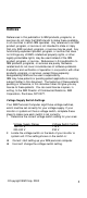
Operating Requirements All machines require two power inputs: one on the system unit and one on the monitor display. The system unit comes with a voltage selector switch, allowing selection of either 115 V ac or 230 V ac. This switch must be in the 115V ac position when the machine is plugged into a 100 – 127 V ac electrical outlet, and 230 V ac position when the machine is plugged into a 200 - 240V ac electrical outlet.
Special Tools The following special tool is required to service this system when running the diagnostics program (PC-Doctor): • Wrap plug, P/N 72X854 65
CheckProcedures Check Procedures ............................................................. 66 Introduction .......................................................................... 67 Start...................................................................................... 68 Index of Symptoms, Messages, Error Codes, or Beeps .... 74 Troubleshooting ................................................................... 87 Factory-Installed Storage Devices................................
Introduction This chapter contains the check procedures used to diagnose the causes of product failures. The diagnostic information consists of: Start: This is the starting point for any diagnostic action. Based on high-level symptoms, the check procedure directs you to more detailed procedures to help resolve machine failures.
Start This is the entry point for all check procedures. The check procedures use failure symptoms, Power-On Self Test (POST) error codes, or beeps to help determine the defective field replaceable unit (FRU). Follow the suggested check procedures or use the diagnostics diskette to determine the problem FRU. IMPORTANT: Replace FRUs ONLY when it is determined that the error is not a result of software, loose contacts, or dirty component surfaces.
range of diagnostic utilities to determine the operating condition of the computer’s hardware components. The diagnostic program includes the following: • PC-Doctor’s Diagnostic Software This interface serves as the control program for running both the IBM PC Enhanced Memory Diagnostics and the suite of diagnostic tests provided by PC-Doctor.
If a newly replaced FRU does not correct the problem: If you have reached this point of the check procedures and were instructed to replace a FRU but doing so did not correct the problem, reinstall the original FRU and go through "Start" again. If you want to print a copy of a BIOS Setup Utility screen to an attached printer, press Print Screen key, while the screen is displayed. PLEASE READ THE FOLLOWING: Human Error is a cause for concern when applied to check procedures.
q Make sure that the monitor refresh rate is correct. q Note any symptoms, messages, error codes, or beeps. q Make sure that there are no diskettes or CDs in the drives. 002 - DOES AN IBM LOGO SCREEN APPEAR? (YES, READ AHEAD. NO, GO TO STEP 004.) q Insert the diagnostics diskette in the diskette drive.
005 q If the keyboard responds incorrectly, go to "Keyboard" on page 96. 006 - q DOES THE SYSTEM CONFIGURATION REPORT CORRECTLY IDENTIFY THE DEVICES INSTALLED IN SYSTEM? (YES, READ AHEAD. NO, GO TO STEP 007.) Select Diagnostics from the diagnostics program menu. q Select and execute All Tests. q Go to step 008. 007 The system configuration report shows only those devices supported by the diagnostics diskette.
008 - DOES THE DIAGNOSTICS FINISH WITHOUT ANY ERRORS? (YES, READ AHEAD. NO, GO TO STEP 009.) q If the Diagnostics \ All Tests did not detect a failure but the system still indicates a failure: q Check all adapter card jumper settings. q Check all adapter cards switch settings. q Check all adapter card cables and connectors. q Make sure that all of the above are set correctly and show the correct voltages and continuity. Replace any defective cables or adapter cards.
Index of Symptoms, Messages, Error Codes, or Beeps How to Use Error Messages: Use the messages, error codes, and beeps combinations that occur to diagnose failures. If more than one failure occurs, diagnose from the first failure that appears. The cause of the first failure can result in false messages, error codes, or beeps. If you did not receive any messages, error codes, or beeps, see if the symptom is listed in Table 2-3, "Error Symptoms List” on page 79.
NOTES: If an error message and incorrect audio response occur, diagnose the error message first. If you cannot run the diagnostics program tests but did receive a POST error code, diagnose the POST error message. If you did not receive any error message, look for a description of your error symptoms in “Error Symptoms List” in page 79. Check all power supply voltages, switch, and jumper settings before you replace the system board.
Table 2-1 BIOS Error Codes, Messages, and Beeps List BIOS Error Codes, Messages, beeps Action/FRU NOTE: To diagnose a problem, first find the BIOS error messages, codes, or beeps in left column. If directed to a check procedure, replace the FRU indicated in the check procedure. If no check procedure is indicated, the first Action/FRU listed in right column is the most likely cause. Memory test failure. Insert the memory modules in the DIMM sockets properly, and then reboot the system. Memory module.
Table 2-1 BIOS Error Codes, Messages, and Beeps List BIOS Error Codes, Messages, beeps Action/FRU NOTE: To diagnose a problem, first find the BIOS error messages, codes, or beeps in left column. If directed to a check procedure, replace the FRU indicated in the check procedure. If no check procedure is indicated, the first Action/FRU listed in right column is the most likely cause.
Table 2-2 BIOS Error Codes, Messages, and Beeps List BIOS Error Codes, Messages, beeps Action/FRU NOTE: To diagnose a problem, first find the BIOS error messages, codes, or beeps in left column. If directed to a check procedure, replace the FRU indicated in the check procedure. If no check procedure is indicated, the first Action/FRU listed in right column is the most likely cause.
Table 2-3 Error Symptoms List Error Symptoms Action/FRU NOTE: To diagnose a problem, first find the error symptom in the left column. If directed to a check procedure, replace the FRU indicated in the check procedure. If no check procedure is indicated, the first Action/FRU listed in right column is the most likely cause.
Table 2-3 Error Symptoms List Error Symptoms Action/FRU NOTE: To diagnose a problem, first find the error symptom in the left column. If directed to a check procedure, replace the FRU indicated in the check procedure. If no check procedure is indicated, the first Action/FRU listed in right column is the most likely cause. System works but fails to enter power saving mode when the Power Management is to Enabled, and power saving timer set in BIOS has elapsed. Load default settings.
Table 2-3 Error Symptoms List Error Symptoms Action/FRU NOTE: To diagnose a problem, first find the error symptom in the left column. If directed to a check procedure, replace the FRU indicated in the check procedure. If no check procedure is indicated, the first Action/FRU listed in right column is the most likely cause. Media and drive are mismatched. Make sure that the diskette drive is configured correctly in the Disk Drives of BIOS Setup. Make sure that the diskette drive is correctly formatted.
Table 2-3 Error Symptoms List Error Symptoms Action/FRU NOTE: To diagnose a problem, first find the error symptom in the left column. If directed to a check procedure, replace the FRU indicated in the check procedure. If no check procedure is indicated, the first Action/FRU listed in right column is the most likely cause. Hard disk drive LED fails to light, but system operates normally.
Table 2-3 Error Symptoms List Error Symptoms Action/FRU NOTE: To diagnose a problem, first find the error symptom in the left column. If directed to a check procedure, replace the FRU indicated in the check procedure. If no check procedure is indicated, the first Action/FRU listed in right column is the most likely cause. CD-ROM drive can play audio CD but no sound output.
Table 2-3 Error Symptoms List Error Symptoms Action/FRU NOTE: To diagnose a problem, first find the error symptom in the left column. If directed to a check procedure, replace the FRU indicated in the check procedure. If no check procedure is indicated, the first Action/FRU listed in right column is the most likely cause.
Table 2-3 Error Symptoms List Error Symptoms Action/FRU NOTE: To diagnose a problem, first find the error symptom in the left column. If directed to a check procedure, replace the FRU indicated in the check procedure. If no check procedure is indicated, the first Action/FRU listed in right column is the most likely cause. Make sure that the printer driver is properly installed. Printing failed. Refer to the service manual for the printer. Printer. Printer cable. System board. Printer problems.
Table 2-3 Error Symptoms List Error Symptoms Action/FRU NOTE: To diagnose a problem, first find the error symptom in the left column. If directed to a check procedure, replace the FRU indicated in the check procedure. If no check procedure is indicated, the first Action/FRU listed in right column is the most likely cause. Pressing power switch cannot turn on system.. Check the voltage selector on the power supply if it is off. Power switch cable assembly. Executing software Load default settings.
Troubleshooting Failing Parts or Assemblies: The check procedures generally help you trace a problem to one part or assembly. The last step of the specific check procedure you are using indicates that a part or assembly is failing. You should inspect the part or assembly before you decide to replace it. It might be loose, dirty, or in need of a small repair. The check procedures might lead you to two, or even three, possible failing parts or assemblies.
Factory-Installed Storage Devices Use this check procedure to test any factory-installed drives. ATTENTION: The customer may have customized settings in the Setup Utility (other than default settings) on the computer you are servicing. Running the Setup Utility might alter those settings. Take note of the current settings and verify that the customer settings are in place when service is complete.
004 - IF THE NUMBER OF DISKETTE, HARD DISK, OR CD-ROM DRIVE IS NOT CORRECT, READ AHEAD; OR GO TO STEP 005. q Check the cable installation of all disk drives. q Diskette drive should be connected to the system board Floppy connector. (Please refer to the connectors and functions illustrated in chapter 5.) q IDE Primary Channel Master and Slave Drives in BIOS Setup should be connected to the system board primary IDE connector. (Please refer to the connectors and functions illustrated in chapter 5.
q If an error or other symptom appears, go to “Index of Symptoms, Messages, Error Codes, or Beeps” on page 74. q If no error can be detected or the symptom is intermittent, go to “Undetermined Problems” on page 104. q End.
Factory-Installed Modem Card 001 - START q Power off the system unit. q In Windows 98 Device Manager, make sure that the modem is not configured with a conflicting COM port and IRQ setting. q Make sure that the communication software is configured with the correct COM and IRQ settings (same as COM port and IRQ as the modem). q Make sure that all communication parameters (baud rate, data, stop and parity bits) are properly configured and are identical on both sides.
004 - CAN THE MODEM DIAL OUT AND CONNECT TO ANY BBS SUCCESSFULLY? (YES, READ AHEAD. NO, GO TO STEP 005.) q The modem adapter functions normally. q End. 005 q Make sure that Windows 98 is properly installed, then power off the system unit. q Plug the modem adapter card into a different PCI slot. q Go to step 002. q If the error symptom still remains, replace the modem adapter card. q End.
Audio (Not Supported by Diagnostics Program) NOTE: Audio tests for the sound card cannot be carried out in the PC Doctor DOS diagnostics program. It is, however, possible to carry out a dial tone test for the modem. While performing this check, you may need to enter and exit Microsoft Windows 98 several times. When instructed to select an icon or button, double-click on the item with the mouse. For more information about using Microsoft Windows 98, see the user's guide that came with the computer.
004 q Perform the following under Windows 98. NOTE: If an operating system other than Microsoft Windows 98 is installed, the program screens and icons may differ from these instructions. 1. Start Microsoft Windows 98. 2. Select the Start icon. 3. Select Settings, then select Control Panel. 4. Select the Sound icon. 5. In the Sound window, select chimes from the Names field. (To test other adapter card software, select an action from a menu in that software.
CD-ROM Drive 001 - START q Insert the diagnostics diskette into the diskette drive and make sure that there is no CD in the CD-ROM drive. q Select Interactive Tests menu, then select and execute CD-ROM Test. 002 - DO YOU SEE A MESSAGE “NO CD-ROM DRIVE OR MSCDEX DEVICE DRIVER INSTALLED.” ? (YES, READ AHEAD. NO, GO TO 003.) q Exit the diagnostics program and power off the system.
q Power on the system unit. q Take note of any messages, error codes, or symptoms. 002 - q DO YOU RECEIVE POST MEMORY ERROR MESSAGE? (YES, READ AHEAD. NO, GO TO STEP 003) Enter BIOS Setup Utility then reboot the system. Take note of any messages, error codes, or symptoms. If the error message remains, go to step 005. 003 q Follow the screen instructions to run the Memory test. 004 - DOES THE MEMORY TEST COMPLETE WITHOUT AN ERROR? (YES, READ AHEAD. NO, GO TO STEP 005.
003 - DOES THE KEYBOARD FUNCTION CORRECTLY? (YES, READ AHEAD. NO, GO TO STEP 004.) q Keyboard is functioning normally. q End. 004 - ARE THERE ANY STUCK KEYS OR ANY GRIME IN THE GAP OF KEYCAPS? (YES, READ AHEAD. NO, GO TO STEP 005.) q Power off the system unit. Carefully remove the grime and solve the stuck keys problem. q Go to step 001. 005 - q ARE THERE ANY BROKEN PINS IN THE KEYBOARD PLUG? (YES, GO TO STEP 007. NO, READ AHEAD.) Try with a known good keyboard.
q Test right (left) button and check if right (left) button works. 004 q DOES THE MOUSE BUTTON WORK? (YES, READ AHEAD. NO, GO TO STEP 007) Test mouse cursor movement. 005 - DOES THE MOUSE MOVE SMOOTHLY AND KEEP X AND Y COORDINATES CHANGED? (YES, READ AHEAD. NO, GO TO STEP 006) q Mouse is functioning normally. q End. 006 q Power off the system unit. q Open mouse bottom cover and clean track ball. q Go to step 002. 007 q Power off the system unit. q Check the mouse plug.
Power Supply 001 - START q Power off the system unit. q Check the power cord for continuity. Replace if necessary. q Check for the correct line voltage from the power outlet, and verify that the voltage selector switch is set to the correct voltage. q Power on the system unit. 002 - DOES THE POWER SUPPLY FAN RUN? (YES, GO TO STEP 003. NO, GO TO STEP 004) 003 - DOES THE SYSTEM FAIL TO SHUT OFF WHEN THE ON/OFF SWITCH IS PRESSED? (YES, READ AHEAD.
11 20 1 10 Power Supply Connectors (Bottom View) Hard Drive or CD-ROM End of Power Cable 3.5-In.
006 - ARE THE VOLTAGES CORRECT AND DOES THE FAN RUN? (YES, READ AHEAD. NO, GO TO STEP 009) q The power supply is working normally. q If you suspect the on/off switch cable assembly, see Step 003. q If the fan continues to run when all connectors are plugged back in, go to “Undetermined Problems” on page 104. If the fan stops running when a drive connector is plugged back in, go to "Start" on page 68.
Monitor First, set the system to VGA mode. To do this in Windows 98, press the F8 function key during startup. Safe mode (VGA) will be set for Windows 98. Use the operating system's video setup to change the monitor resolution. If the monitor type is set to the power saving mode, the screen remains black and the LED lights or flashes in amber color. When the monitor is turned on alone, or is turned on and connected to a powered-off system unit, the monitor LED blinks in amber color.
002 - IS THE SCREEN READABLE? (YES, READ AHEAD. NO, GO TO STEP 004) NOTE: If the screen shows a blinking cursor with no memory count running, answer this question "No". q Select Interactive Tests from the Main Menu. q Select and execute Video test from the menu. q Follow the prompts and perform the video test. q Go to “Index of Symptoms, Messages, Error Codes, or Beeps” on page 74. NOTE: 003 - You might have to adjust the monitor controls to obtain the best image.
Undetermined Problems If an error code is present, go to “Index of Symptoms, Messages, Error Codes, or Beeps” on page 74. If no error code is present, continue with this check. Check the power supply voltages (see “Power Supply Cable Connector Specifications" on page 129). If the voltages are correct, return here and continue with the following steps: 1. Power off the system unit. 2.
Diagnostic Aids Diagnostic Aids.................................................................. 105 Introduction .......................................................................... 106 Power-On Self Test ............................................................. 106 Diagnostics Tools ................................................................ 107 Diagnostics Program Features .....................................
Introduction This section explains the diagnostic aids, power-on self test (POST) and diagnostics program (PC-Doctor), that are available for troubleshooting problems on the system. Power-On Self Test Each time you power-on the system, the power-on self test (POST) is initiated. Several items are tested during POST, but is for the most part transparent to the user.
4. If no keyboard keys are pressed, and if POST is completed without errors, the system will then proceed with the loading of DOS or other operating system from diskette drive A or a hard disk drive or CD-ROM drive, depending on the options selected in the Setup Utility. If any errors are detected by POST, there will be an error message accompanied with an error code shown on display screen and a beep.
3. 4. 5. 6. 7. 8. 9. Turn off your computer. If the computer will not turn off after you hold down the power button for at least four seconds, unplug the power cord and wait a few seconds before reconnecting it. Turn on your computer. Wait for the prompt, To start the Product Recovery program, press F11. Quickly press F11. The prompt displays for only a few seconds. If you are using a CD, wait for the Product Recovery program menu to appear on the screen.
Hardware Info • • • • • • • • • • • • • • • • • • • • Onboard Ethernet USB Port System Configuration Memory Contents IRQ and DMA Use Device Drivers COM and LPT Ports Physical Disk Drives Logical Disk Drives VGA Information Software Interrupts SCSI Devices I/O Use IDE Drive Info Network Information PCMCIA Information PCI Information SMP Information PNPISA Info DMIBIOS Info Utility • • • • • Log File Utilities Surface Scan Hard Disk Run External tests Tech Support Form Select Language Quit • • • • Exi
Repair Information Repairing Information ....................................................... 110 Removals and Replacements of machine type ................. 111 Identifying the Parts of the System Unit.............................. 112 Top Cover ............................................................................ 114 Adapter Cards ............................................................... 115 Diskette Drive ................................................................ 117 CD-ROM Drive ..
Removals and Replacements of machine type 2169 BEFORE REMOVING ANY FRU, POWER-OFF THE COMPUTER UNPLUG ALL POWER CORDS FROM ELECTRICAL OUTLETS, THEN DISCONNECT ANY INTERCONNECTING CABLES. ATTENTION: The System board, processors, adapter cards, DIMMs, and upgrade processors can be damaged by electrostatic discharge. Use an electrostatic discharge (ESD) strap to establish personal grounding.
Identifying the Parts of the System Unit This computer system has 4 bays, each bay may have a factory-installed drive in it. The devices are 3.5” Diskette, 40X CD-ROM drive (some models only) and 5.0 GB hard disk (some models may have hard disk of 7.5 or 10 GB capacity). Diskette drives in this unit use the standard diskette advanced technology (AT) Interface. Hard disk and CD-ROM drives in this unit use an integrated drive Electronics (IDE) AT interface.
1. CD-ROM Drive This machine has a factory-installed 40 X CDROM drive. 2. Power Supply 150Watt power supply 3. Diskette Drive This machine has a factory-installed 3.5” 1.44MB Floppy drive. 4. Hard Disk Drive This machine has a factory-installed 3.5” (5 min) GB hard disk drive. 5. CPU 6. Fansink 7. System Board 8. Modem card The system may include a V.90 Data/Fax modem. 9. Diskette cable 10.Hard disk drive cable 11.Front Bezel Assy.
Top Cover To remove the top cover of this system unit: q Remove the 3 screws that secure the top cover at the back of the system unit. q Hold both sides of the system unit cover and push it backward about 25 mm. q Lift the top cover up to remove it completely. q Touch the bare metal frame of your system unit to dissipate the static electricity from your body. Do not touch any of the components inside the frame before you touch the frame.
Adapter Cards Installing Adapter Cards q Remove the screw that secures the adapter card retainer and slot cover. Then remove the card retainer and slot cover. q Align and insert the adapter card into the adapter card connector. q Secure the card with the screw that you removed in the first step. q Reinstall all hardware (except for the slot cover, which cannot be reinstalled) and screws that you removed prior to the installation of the adapter card.
Removing Adapter Cards Follow these steps to remove an adapter card: q Position the system unit so that the card is accessible to you. q If the adapter card has cables, disconnect them. Be sure to take note of where the cable is connected. You will have to reconnect these cables when you reinstall the card. q Remove the adapter card screw q Firmly hold the adapter card and carefully pull it from the card connector.
Diskette Drive To remove the diskette drive: q Disconnect the power and signal cables from the back of the diskette and HDD drives. q Remove the single screw on the side of the cage q Remove the diskette mounting tray from the chassis as following illustration : q Slide the drive-mounting tray toward the rear of the computer and remove it. (Illustration below shows replacement direction).
CD-ROM Drive To remove CD-ROM Drive: q Disconnect the power, sound and signal cables from the CD-ROM. q Remove the four screws (two on each side) that hold the CD-ROM drive to the chassis. q Open the door on the front of the computer. q Slide the CD-ROM drive forward through the front opening and remove it.
Hard Disk Drive To remove or replace the hard disk drive: q Disconnect the power and signal cables from the back of the diskette and HDD drives. q Remove the single screw on the side of the cage q Remove the diskette mounting tray from the chassis as following illustration : Slide the drive-mounting tray toward the rear of the computer and remove it. (Illustration below shows replacement direction).
System Board To remove the system board from the system: q To remove the system board. You must remove the adapter cards first. q Disconnect the power cable, CD-ROM cable, Diskette Drive cable, Hard Disk Drive cable, audio cable, power switch cable and LED cables from system board. q Remove the three screws on the back planar plate. q Slide the plate forwards and lift out with the syatem board together. Note: Be sure to keep the I/O Port Bracket on chassis when replacing the system board.
Power Supply This system has a 150-watt switching power supply. 1. To remove the power supply. You must remove the top cover first. 2. Disconnect the power cable from the riser board and all drives. 3. Remove the screws in the machine rear that secure the power supply. Memory (DIMM) This system has 2 system memory module sockets, DIMM 0 and DIMM 1. These sockets hold dual in line memory modules (DIMM) that contains 3.3V signal or double-sided synchronous DRAM (SDRAM).
Parts/Test Point Locations Parts/Test Point Locations ............................................... 122 Introduction .......................................................................... 123 System board Layout Power Supply Cable Connector Specifications .................. 129 Main Output Pin Assignment ........................................ 130 Factory-Installed Modem Card Layout................................ 132 Factory-Installed Modem Card Connector Functions .. 132 3.5-In.
Introduction This chapter contains system board layouts and jumper settings. It is useful when you are asked to measure voltages. Use this information to help you locate parts such as electronic boards, connectors, pin numbers, and test points. This chapter also contains jumper settings for the hard disk drive, CD-ROM (compact disc-read-only memory) drive, and the connector information for modem adapter card.
Layout of system board of the machine type 2169 CPUFAN1 ATX1 DIMM1 DIMM2 JP2 Socket-370 COM2 JP3 FDD1 IDE2 SIR1 IDE1 CASFAN1 LED1 CD2 CD1 TV-Out/LCD Panel Riser Slot PANEL1 PCI1 WOM1 MODEM2 PCI2 LED2 JP1 FP1 J1 J2 WOL1 Component Socket-370 PCI 1, 2 TV-Out/LCD Panel Riser DIMM 1, 2 FDD1 IDE1, IDE2 ATX1 SIR1 PANEL1 WOM1 WOL1 USB1 *LED1 **LED2 COM2 CASFAN1 CPUFAN1 MODEM2 CD1 124 USB1 Description Socket for PPGA Celeron Processor Two 32-bit PCI Slots Slot for a TV-Out/LCD Panel Riser card.
CD2 Auxiliary audio connector for CDROM/DVD drive FP1 J1 J2 JP1 JP2 Auxiliary microphone and speaker out Chassis open detect connector Connector for two-color LED Clear CMOS memory jumper Function disabled – not used JP3 Force system bus frequency to 100 MHz jumper *LED1 This red indicator turns on if your system is suspended to RAM. In a suspend to RAM, the system turns off most of the power-consuming components except for the 3.3V required to refresh the memory.
t CPU FAN : CPU cooling FAN Power connector. Pin 1 nearest to cpu Pin No. Function 1 GND. 2 +12V 3 SENSE t CAS FAN: Power FAN Connector. Pin 3 nearest to cpu Pin No. 1 GND. 2 +12V 3 SENSE Function t JP1 : Clear CMOS. Pin 1 marked on pcb Pin No. 1-2 close 2-3 close Function Normal operation (Default). Clear CMOS t CD1: CD Audio Line in. Pin 4 nearest to cpu Pin No. 1 2,3 4 Function CD_L GND CD_R t CD2 :AUX_IN. Pin 1 nearest to cpu Pin No.
PANEL1: PANEL CONNECTORS FOR SWITCHES AND INDICATORS The panel connector is used to implement the switches and indicators on your system case. Note: Only pins 15, 16 (Hard Disk Indicator) and pins 21, 22 (Power Switch) are used on 2169 standard models. Connector J2, referred to on the system board diagram is used for the power on LED.
Replacing the system battery Follow these steps to replace the battery: 1. Place the blade of a small, flat-blade screwdriver under the edge of the retaining clip. 2. Turn the screwdriver one quarter turn, raising the clip while pressing down on the old battery to remove it. 3. Carefully raise the retaining clip, and insert the new battery with the + symbol facing out. 4.
Power Supply Cable Connector Specifications Refer to the following figures when checking for voltages on power supply cable connectors. When checking voltages, the power supply fan must be running. To power on the power supply without using the on/off switch, use a screwdriver or other tools to short the power supply connector (with the switch cable disconnected from the connector on the system board) or use a connection (jumper) to short the black and green wires of the 20-pin connector on power supply.
Main Output Pin Assignment Table 5-7. Main Output Pin Assignment Pin Function Color 1 +3.3 V Orange 2 3.3 V Orange 3 COMMON BLACK 4 +5Vdc RED 5 COMMON BLACK 6 +5Vdc RED 7 COMMON BLACK 8 POWER GOOD GRAY 9 +5Vs PURPLE 10 +12Vdc YELLOW 11 3.3V Orange 12 -12Vdc BLUE 13 COMMON BLACK 14 P.
Hard Drive or CD-ROM Power Cable Connector 3.5-In.
Factory-Installed Modem Card Layout 1 2 Factory-Installed Modem Card Layout Factory-Installed Modem Card Connector Functions Item Function Connect to… 1 Telephone line-out Some modem adapters may come without this jack. Telephone set 2 Telephone line-in Telephone line NOTE: 132 Care should be taken while connecting the voicein/speaker-out connector. The longer exposed end (approx. 15mm) of the cable should be connected to the modem card. The other end should be connected to the system board.
3.5-In. Hard Disk Drive Jumper Locations & Settings 3.
CD-ROM Drive CD-ROM Front Panel NOTE: Item Position of CD-ROM switches and LEDs may vary from illustration. Description 1 Load / eject button 2 Headphone jack 3 Power-on / busy indicator, lights up in green color while disc is set in ready state; lights up and flashes in amber color during data read or seek operation. 4 Headphone volume control 5 Emergency eject hole. See CD-ROM Emergency-exit below.
CD-ROM Drive Rear Panel Connectors and Features NOT USED 1 2 5 CABLE SELECT SLAVE MASTER IDE AUDIO R GGL CSM SLA 1 2 5V G 2 3 4 DC INPUT INTERFACE 39 40 G 12V 1 CD-ROM Rear Panel Item Function Connect to… 1 Power supply connector Power supply 2 IDE Connector IDE channel on system board. 3 CD-ROM drive jumper settings -- 4 Audio out CD1 5 Not Used -- CD-ROM Drive Jumper Settings CS SL MA DESCRIPTION -- -- On Drive configured as a Master.
System Board Connector Pin Signals Monitor Port Signals Pin Signal Name I/O Pin Signal Name I/O 1 Red Video O 2 Green Video O 9 +5 V dc N/A 10 Synch Ground N/A 3 Blue Video 4 No Connection O 11 No Connection N/A N/A 12 Monitor ID Bit 1 I 5 Synch Ground 6 Red Ground N/A 13 Horizontal Synch O N/A 14 Vertical Synch O 7 8 Green Ground N/A 15 Monitor ID Bit 3 I Blue Ground N/A Serial Port Signals Pin Signal Name I/O Pin Signal Name I/O 1 Data Carrier Detect
7 Data Bit 5 I/O 20 Ground Power 8 Data Bit 6 I/O 21 Ground Power 9 Data Bit 7 I/O 22 Ground Power 10 Acknowledge I 23 Ground Power 11 Busy I 24 Ground Power 25 Ground Power 12 Paper Empty I 13 Select O Mouse Port Signals Pin Signal Name I/O Pin Signal Name 1 Mouse Data I/O 4 +5 V dc 2 No Connection N/A 5 Mouse Clock I/O 3 Ground No Connection N/A Power 6 I/O Power Keyboard Port Signals Pin Signal Name I/O Pin Signal Name 1 Keyboard Data I/O
Diskette Drive Cable Connector Signals Pin Signal Name I/O 1 No Connection N/A 18 2 Density Select 3 No Connection O Pin 19 N/A 20 I I/O O Ground Step O High Density Out 5 Ground N/A 22 6 No Connection N/A 23 Ground 7 Ground N/A 24 Write GATE 8 Index 25 Ground N/A 9 Ground N/A 26 Track 0 I 10 No Connection N/A 27 Ground N/A 11 Ground N/A 28 Write Protect Drive Select 1 13 Ground N/A 30 Read Data 14 No Connection N/A 31 Ground 15 Ground N/A 32 SIDE
IDE Cable Connector Signals Pin Signal Name I/O Pin Signal Name I/O 1 Host Reset O 21 DMA Request 2 Ground N/A 22 Ground 3 Host Data 7 I/O 23 Host IOW 4 Host Data 8 I/O 24 Ground 5 Host Data 6 I/O 25 Host IOR 6 Host Data 9 I/O 26 Ground 7 Host Data 5 I/O 27 8 Host Data 10 I/O 28 No Connection 9 Host Data 4 I/O 29 DMA Acknowledge 10 Host Data 11 I/O 30 Ground 11 Host Data 3 I/O 31 Host IRQ 12 Host Data 12 I/O 32 No Connection 13 Host Data 2 I/
Safety Inspection Guide Safety Inspection Guide ................................................... 140 General Guidelines .............................................................. 141 Copyright IBM Corp.
General Guidelines The purpose of this Safety Inspection Guide is to help you identify possible unsafe conditions on machines that are being inspected for a Maintenance Agreement. Each machine has necessary functions items installed to provide the operators and service personnel with an acceptable level of safety. This guide lists only these items. Good judgment should be used to identify possible safety conditions not covered by this Safety Inspection Guide.
Parts Catalog Part Catalog of machine type ............................................. 144 Assembly 1: System Unit..................................................... 144 Assembly 2: Diskette Drive, Hard Disk Drive ................ 147 Assembly 3: CD-ROM, Modem Card............................. 148 Assembly 4: Keyboard and Mouse ................................ 150 Copyright IBM Corp.
Part Catalog of machine type 2169 Assembly 1: System Unit Asm-Index FRU Number 1 See Assy 3 2 11P7621 3 See Assy 2 Floppy Disk Drive 4 See Assy 2 HDD Drive 5 09N9307 INTEL Celeron 533MHz assy with fansink 6 06P2446 Fansink, Supports Celeron (non-PIII base) Processors 7 11P7551 ECS P6IWP-Fe i810 Planar 8 See Assy 3 56.
10 See Assy 2 HDD/CD-ROM IDE cable 11 11P7557 Front bezel assy 12 11P7447 32MB module (PC100) Not Shown 14F0032 Power Cord UK/HK/Singapore Not Shown 13F9978 Power Cord Euro Not Shown 14F0050 Power Cord Swiss Not Shown 13F9996 Power Cord Denmark Not Shown 14F0014 Power Cord South Africa Not Shown 62X0663 Power Cord Saudi Arabia Not Shown 14F0068 Power Cord Italy, Chile Not Shown 14F0033 Power Cord Arabic Not Shown 14F0086 Power Cord Israel Not Shown 11P7555 Top Cover No
Not Shown 11P7610 ECS Screw Kit (All screws except CD and HDD).
Assembly 2: Diskette Drive, Hard Disk Drive Asm-Index FRU Number Description 2-1 19K1583 5 GB Hard Disk Drive, 3.5” 2-2 11P7556 3.
Assembly 3: CD-ROM, Modem Card Asm-Index FRU Number 3-1 09N0879 40X CD-ROM, LG 3-1 19K1515 40XCD-ROM, LITEON 3-2 37L5098 CD-ROM IDE Cable 3-3 75H9219 CD-ROM Audio Cable (2169) 3-5 09N1676 Modem, 56K Data Fax, GVC EMEA/ANZ/India/Singapore 3-4 09N1626 Modem, 56K Data Fax, Askey EMEA 3-5 36L9016 Phone Cord Not Shown 60H6023 Modem Phone Cable Adapter Spain/Southern Ireland Not Shown 60H6026 Modem Phone Cable Adapter Belgium 148 Description
Not Shown 60H6027 Modem Phone Cable Adapter Denmark Not Shown 60H6028 Modem Phone Cable Adapter Norway/Finland Not Shown 60H6029 Modem Phone Cable Adapter FR Not Shown 60H6030 Modem Phone Cable Adapter Germany Not Shown 60H6031 +60H6023 Modem Phone Cable Adapter UK/Northern Ireland Not Shown 60H6032 Modem Phone Cable Adapter Italy Not Shown 60H6033 Modem Phone Cable Adapter Netherlands Not Shown 60H6034 Modem Phone Cable Adapter Sweden Not Shown 60H6035 Modem Phone Cable Adapter Sw
Assembly 4: Keyboard and Mouse 4-2 4-1 4-3 Asm-Index FRU Number 4-1 10L6145 IBM Mouse 4-2 37L2518 105 PALM REST ARABIC 275 4-2 37L2519 105 PALM REST, EURO BELGIUM/FR 120 4-2 37L2520 4-2 37L2521 4-2 37L2522 4-2 37L2523 4-2 37L2524 4-2 37L2525 4-2 37L2526 4-2 37L2527 4-2 37L2528 150 Description 105 PALM REST, EURO BELGIUM/UK 120 105 PALM REST BULGARIAN 442 105 NO PALM REST CZECH 243 105 PALM REST, EURO DANISH 159 105 PALM REST, EURO DUTCH 143 105 PALM REST, EURO FRENCH 189 1
105 PALM REST HUNGARIAN 208 105 PALM REST ICELANDIC 197 105 PALM REST, EURO ITALY 142 105 PALM REST, EURO NORWEGIAN 155 4-2 37L2529 4-2 37L2530 4-2 37L2531 4-2 37L2532 4-2 37L2533 105 PALM REST 214 4-2 37L2534 105 PALM REST PORTUGUESE 163 4-2 37L2535 105 PALM REST ROMANIAN 446 4-2 37L2536 104 PALM REST 443 4-2 37L2537 105 PALM REST SERBIAN/CYR 118 4-2 37L2538 105 PALM REST 245 4-2 37L2539 105 PALM REST, EURO SPANISH 145 4-2 37L2540 105 PALM REST, EURO SWED/FINN 153 4-2 37L2
Appendix A. Online Support Information This section describes online technical support services available to help repair the computer. This section covers: q IBM PC Company Fax-Back Service q IBM useful sites on the World Wide Web (WWW) q IBM Online Assistant q Discussion Forums The IBM PC Company offers online resources including several Internet World Wide Web sites, the IBM Online HelpCenter support areas, and a Fax-Back service.
Index A Adapter Cards Installing, 115 Removing, 116 Audio Check Procedure, 93 Error Symptoms, 83 B Beeps, 67, 74, 75 BIOS Flash Update Procedure, 42 Model Number and Serial Number, 43 BIOS setup Utility, 44 C Cabling, 39 CD-ROM Drive, 38, 40, 118, 134 Check Procedure, 95 Connectors and Features, 135 Emergency-exit, 134 Error Symptoms, 82 Front Panel, 134 Jumper Settings, 135 Check Procedures, 66 CMOS Reset, 41 D Diagnostic Aids, 105 Diagnostic Diskette, 85 Diagnostic Program Error symptoms, 85 Diagnostic
M Memory, 37 Check Procedure, 95 DIMM Configurations, 135 Error Symptoms, 79 Model Number, 43 Modem, 39 Check Procedure, 91 Connector Functions, 132 Error Symptoms, 83 Layout, 132 Monitor, Check Procedure, 102 Error Symptoms, 83 Port Signals, 136 Mouse, 39 Check Procedure, 97 Mouse Port Port Signals, 137 Multimedia, 38 O Online Support Information, 152 P Parallel Port, 40 Error Symptoms, 84 Port Signals, 136 Parts Catalog of machine type 2193, 2194 and 6345, 143 CD-ROM, Modem Card, 148 Diskette Drive, Har
Printed in U.