
Specifications


Thermal/Mechanical Design Guide 35
Thermal Solutions
5.3 Assembly
The assembly process for the 1U reference heatsink begins with application of
Honeywell PCM45F thermal interface material to improve conduction from the IHS.
Tape and roll format is recommended. Pad size is 35 x 35mm, thickness is 0.25mm.
Next, position the heatsink such that the heatsink fins are parallel to system airflow.
While lowering the heatsink onto the IHS, align the four captive screws of the heatsink
to the four threaded nuts of the back plate.
Using a #2 Phillips driver, torque the four captive screws to 8 inch-pounds.
This assembly process is designed to produce a static load of 39 - 51 lbf, for 0.062" -
0.100" board thickness respectively. Honeywell PCM45F is expected to meet the
performance targets in Table 5-1 from 30 - 60 lbf. From Table 4-3, the Heatsink Static
Compressive Load of 0 - 60 lbf allows for designs that vary from the 1U reference
heatsink. Example: A customer’s unique heatsink with very little static load (as little as
0 lbf) is acceptable from a socket loading perspective as long as the T
CASE
specification
is met.
Compliance to Board Keepout Zones in Appendix B is assumed for this assembly
process.
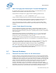
Figure 5-3. 1U Reference Heatsink Assembly
1U Reference Heatsink
Thermal Interface Material:
Honeywell PCM45F
Captive Screw
IHS: Integrated
Heat Spreader
Reference Back Plate
(Unified Back Plate)
Threaded Nut
1U Reference Heatsink
Thermal Interface Material:
Honeywell PCM45F
Captive Screw
IHS: Integrated
Heat Spreader
Reference Back Plate
(Unified Back Plate)
Threaded Nut