IBM PC Servers SY33-0193-00 IBM SerialRAID Adapter for PC Servers Hardware Maintenance Manual Supplement October 1998 Use this supplement with the Hardware Maintenance Manual for the PC Server
IBM PC Servers SY33-0193-00 IBM IBM SerialRAID Adapter for PC Servers Hardware Maintenance Manual Supplement October 1998 Use this supplement with the Hardware Maintenance Manual for the PC Server
Note Before using this information and the product it supports, be sure to read the general information under “Notices” in the product documentation.
Contents About This Supplement . . . . . . . . . . . . . . . . . . . . . . . . . . . . . . . How This Book Is Organized . . . . . . . . . . . . . . . . . . . . . . . . . . . . . Related Publications . . . . . . . . . . . . . . . . . . . . . . . . . . . . . . . . . v v vi Introducing the IBM SerialRAID Adapter . . . . . . . . . . . . . . . . . . . . . General Information . . . . . . . . . . . . . . . . . . . . . . . . . . . . . . . . . . 1 2 Service Request Numbers (SRNs) . . . . Displaying SRNs . . . .
iv The Identify Function . . . . . . . . . . . . . . . . . . . . To Identify with the DOS Configurator . . . . . . . . . To Identify With the RSM Configurator . . . . . . . . . Download Microcode Function . . . . . . . . . . . . . . . Finding the Physical Location of a Device . . . . . . . . . . Finding the Device When Service Aids Are Available Finding the Device When No Service Aids Are Available The Event/Error Logger . . . . . . . . . . . . . . . . . . . Analyze SSA Event Log . . . . . . . . . . . . .
About This Supplement This book is intended for service representatives who maintain PC servers that use the IBM SerialRAID Adapter. How This Book Is Organized “Introducing the IBM SerialRAID Adapter” on page 1 introduces the IBM SerialRAID Adapter. “Service Request Numbers (SRNs)” on page 3 provides a table of service request numbers (SRNs) that are related to the IBM SerialRAID Adapter. “Removing and Replacing FRUs” on page 19 describes how to exchange disk drives, DRAMs and the Fast-Write cache.
Related Publications Other manuals that you might find useful are: IBM SerialRAID Adapter: Installation and User’s Guide, S33-3283-00 IBM SerialRAID Adapter: Technical Reference, SA33-3275-01 For more information, contact IBM or your IBM Authorized Dealer.
Introducing the IBM SerialRAID Adapter The IBM SerialRAID Adapter is a Peripheral Component Interconnect (PCI) adapter that serves as the interface between systems based on PCI architecture and devices that use Serial Storage Architecture (SSA). The adapter has four ports, which can be connected in pairs to drive two SSA loops. Each loop can contain a maximum of 48 disk drives. Two adapters, each one located in a different PC Server, can drive the same SSA loop.
Flashing continuously: One of the ports is not operational. This condition occurs if the cable to the port is not connected correctly, or if the device in the loop connected next to the adapter is not operational. Off: Both ports are non-operational. General Information For general information regarding the IBM SerialRAID Adapter, RAID technology and SSA loops, see the IBM SerialRAID Adapter: Installation and User's Guide.
Service Request Numbers (SRNs) Service request numbers (SRNs) are generated by the error logging facility and by the diagnostics. SRNs help you to identify the cause of a problem, the failing field-replaceable units (FRUs), and the service actions that might be needed to solve the problem. Displaying SRNs To see the SRNs run the Remote Systems Management (RSM) Configurator.
1. Find the SRN in the table. If you cannot find the SRN, refer to the documentation for the subsystem or device. If you still cannot find the SRN, you have a problem with the diagnostics, the microcode, or the documentation. Call your support center for assistance. 2. Read carefully the “Action” you must do for the problem. Do not exchange adapters unless you are instructed to do so. 3. Normally exchange only one adapter at a time.
FRU List Problem 40032 SRN 32 MB DRAM module 0 (100%) (“Exchanging DRAMs on the IBM SerialRAID Adapter” on page 22). Description: A 32 MB DRAM in adapter card module 0 has failed. Action: Exchange the FRU for a new FRU. 40064 64 MB DRAM module 0 (100%) (“Exchanging DRAMs on the IBM SerialRAID Adapter” on page 22). Description: A 64 MB DRAM in adapter card module 0 has failed. Action: Exchange the FRU for a new FRU.
SRN 42500 FRU List Problem Fast-Write Cache Card (98%) (“Exchanging the Fast-Write Cache Card” on page 23) SSA Adapter Card (2%) (Installation and User Guide) Description: The Fast-Write Cache Card has failed. Action: 1. Exchange the Cache Card for a new one 2. Switch on power to the using system 3. New error codes are produced if the original cache card contained data that was not moved to a disk drive. Run diagnostics on the adapter and if a SRN is produced, do the actions for that SRN.
SRN 42520 FRU List Problem Fast-Write Cache Card (100%) Description: A Fast-Write Cache Card has failed. Data has been written to the cache card and cannot be recovered. The location of the lost data is not known. The disk drive is offline. Action: 1. Ask the customer to determine: Which disk drives are affected by this error How much data has been lost Which data recovery procedures can be done 2.
SRN 42522 FRU List Problem Fast-Write Cache Card (100%) (“Exchanging the Fast-Write Cache Card” on page 23) Description: A Fast-Write Cache card has failed. Data has been written to the card and cannot be recovered. One or more 4 KB blocks of data for a known disk have been lost and cannot be read. Action: 1. Ask the customer to determine: Which disk drives are affected by this error How much data has been lost Which data recovery procedures can be done 2.
SRN 42525 FRU List Problem None Description: The wrong Fast-Write Cache Card has been detected by a fast-write disk drive that contains unsynchronized data. Action: The failing disk drive is offline. If the disk drive has just been moved from another adapter, do either of the following actions: Return the disk drive to its original adapter. Move the original Fast-Write Cache card to this adapter so that the data can be synchronized.
FRU List Problem 44PAA SRN Device (100%) (“Exchanging Disk Drives” on page 19). Description: An SSA device has a ‘Failed’ status. Action: If the SSA service aids are available, run the Disk service aid (see “Service Aids and Other Utilities” on page 29) to find the failing device. If no device is listed as Rejected, use the PAA part of the SRN to determine which device is failing. Before you exchange the failing device, run nonconcurrent diagnostics to that device to determine the cause of the problem.
FRU List Problem 49700 SRN None Description: The parity for the array is not complete. Action: Go to “MAP 2010: START” on page 2010-1. 50000 SSA adapter card (100%) Description: The SSA adapter failed to respond to the device driver. Action: Exchange the FRU for a new FRU. 50001 SSA adapter card (100%) Description: A data parity error has occurred. Action: Exchange the FRU for a new FRU. 50002 SSA adapter card (100%) Description: An SSA adapter DMA error has occurred.
Software and Microcode Errors Some SRNs indicate that a problem might have been caused by a software error or by a microcode error. If you have one of these SRNs, do the following actions: 1. Make a note of the contents of the error log for the device that has the problem. 2. Go to the system service aids and select Display Vital Product Data to display the VPD of the failing system. Make a note of the VPD for all the SSA adapters and disk drives. 3. Report the problem to your support center.
The procedure, using the RSM configurator, for removing the Fast-Write function from a resource when advised to do this is as follows: 1. Start the RSM Configurator and select all the resources that have Fast-Write enabled 2. Perform the following actions on each resource in turn: a. Go to the Resource View page for each resource you want to change b. Select Delete FW Note: All Fast-Write resources are identified with the symbol of a lightening flash against them.
14 IBM SerialRAID Adapter Maintenance Information
SSA Link Errors SSA link errors can be caused by a number reasons, for example if: Power is removed from an SSA device An SSA device is failing An SSA device is removed A cable is disconnected. Errors might be indicated in various ways, such as: SRN 45PAA A flashing link status (Ready) light on the SSA device at each end of the failing link The indication of an open link when using the Disk Service Aid.
Example 2 This link is between two disk drives that are in the same subsystem. It has five parts. SSA Subsystem Internal Disk Drive 1 Connection Dummy Disk Drive Internal Disk Connection Drive 2 Example 3 This link is between two disk drives that are not in the same subsystem. It has seven parts. SSA Subsystem Internal Disk Drive Connection SSA Connector Card SSA Subsystem Cable SSA Connector Card Internal Disk Connection Drive Example 4 This link is between a disk drive and an SSA RAID Adapter.
Status of Light Meaning Off Both SSA links are inactive. Permanently on Both SSA links are active. Slow flash (two seconds on, two seconds off) Only one SSA link is active. If you need more information about the lights, see: For adapter lights, “Introducing the IBM SerialRAID Adapter” on page 1 in this book. For other lights, the service information for the device that contains the lights.
To help locate these disk drives, select the disk drive, and press F9 (FlashOn). The Check light on the selected disk drive flashes. This action does not affect the customer’s operations. For more information about the service aids, see “Service Aids and Other Utilities” on page 29.
Removing and Replacing FRUs Exchanging Disk Drives When a maintenance procedure requires you to replace a faulty disk drive with a new one, first check whether the disk drive to be removed is a member of a RAID array. If the disk drive to be changed IS NOT a member of an array, go to “Exchanging an Array Disk” on page 20. If the disk drive to be changed IS a member of an array, go to “Exchanging a Non-Array Disk Drive.
8. Repeat the procedure given above for any other disk drive that you are changing. 9. If necessary, convert the newly-installed disk drive into a free resource (see the configurator information in the IBM SerialRAID Adapter: Installation and User's Guide). Using the RSM Configurator 1. Start the RSM configurator and select the appropriate adapter from the Adapter List. 2. On the Adapter View page, select the Physical View. 3. On the Physical View page, select the disk drive you want to change. 4.
Exchanging an Array Disk Using the DOS Configurator 1. Start the DOS Configurator. 2. From the Main Menu, select SSA Adapter List, then select the required adapter from the list. 3. From the Adapter Menu, select RAID 5 Resources. 4. Select the array from which you want to remove a disk drive. 5. Select View Members. 6. Select the disk drive that you want to remove. 7. Press F7 (Exchange Members).
The array disk drive is logically removed from the array, returned to the list of Free Resources and replaced by the selected Free Resource. 9. If you need to perform maintenance on the disk drive you have logically removed from the array: a. Display the list of Free Resources. b. Select the disk drive that you logically removed from the array. c. Set Service Mode. You can now physically remove the disk drive for maintenance.
Installing a DRAM 1. Ensure that the DRAM to be installed is the correct type. 2. Insert the DRAM into the keyed socket. 3. Press the DRAM into the socket, then rotate the DRAM until the clips .1/ click into place. 4. Reinstall the adapter into the system unit (see the service information for the system unit). 5. Turn on the power to the system. 6. Start up the system. Exchanging the Fast-Write Cache Card The following procedures explain how to remove and replace the Fast-Write Cache card.
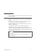
1 Figure 1. The SSA Fast-Write Card Installed on an IBM SerialRAID Adapter 4. Refer to Figure 2.
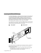
2 1 Figure 2. Releasing the Fast-Write Cache Card 5. Remove the pin .2/ and the collar .1/ from the Fast-Write Cache card. 6. Referring to Figure 3, pull the Fast-Write Cache card .1/ in the direction shown by the arrow in the diagram. This action unplugs the card from the connector on the adapter card.
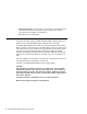
1 Figure 3. Removing the Fast-Write Cache Card Installing the Cache Card Attention Adapter cards contain parts that are electrostatic-discharge (ESD) sensitive. Use the tools and procedures defined by your organization to protect such parts. 1. Remove the adapter from the using system, if not already removed (see the Installation and User Guide for the using system).
1 Figure 4. Installing the Fast Write Cache Card onto a IBM SerialRAID Adapter. 2. Orient the Fast-Write Cache card as shown in the diagram, and place it onto the adapter card. 3. Push the card .1/ in the direction shown by the arrow in the diagram, and plug it into the connector on the adapter card. 4. Refer to Figure 5 on page 28.
1 2 Figure 5. Installing the Collar and Pin of the Fast-Write Cache Card 5. Hold the collar .2/ so that its split end is downward. 6. Install the collar into the Fast-Write Cache card so that its split end is downward. 7. Install the pin .1/ into the collar, and push it fully home. 8. Reinstall the adapter card into the system unit (see the service information for the system unit).
Service Aids and Other Utilities A number of service aids and utilities are available with the DOS Configurator to assist in maintenance tasks. These include: The Disk Service Aids The Identify function The Download Microcode function How to find the physical location of a device Similar functions are available through the RSM Configurator, but the RSM also provides access to Event/Error Logging.
à@ ┌───────────────────────────────────────────────────────────────────────┐ ð │ISSACFG SSA Configurator and Service Aids yymmdd DOS Version│ └───────────────────────────────────────────────────────────────────────┘ ┌──────────────────────────────┐ │ Main Menu │ ├──────────────────────────────┤ │ │ │ SSA Adapter List │ │ Dump Configuration Details │ │ Service Aids │ │ About │ │ │ │ │ │ │ └──────────────────────────────┘ ┌────────────────────────────────────────────────────────────────┐ │ Exit
Service Mode A disk drive must be placed in Service Mode before it can be removed from the SSA loop and maintenance performed on it. When Service Mode is set: The Check light of the disk drive comes on for identification. All SSA loop activity through the disk drive stops. The disk drive motor stops. The Check light (if present) of the enclosure that contains the selected disk drive comes on. The SSA loop is broken and no communication to the disk is possible.
à@ ┌───────────────────────────────────────────────────────────────────────┐ ð │ISSACFG SSA Configurator and Service Aids yymmdd DOS Version │ └───────────────────────────────────────────────────────────────────────┘ ┌────────────────────────────┐ │ Main Menu │ ├────────────────────────────┤ │ ┌─────────────────────────────────────┐ │ │ Disk Service Aids │ │ ├─────────────────────────────────────┤ │ │ Link SSA UID Status │ │ │ Port A1 │ │ │ UIDxxxxx │ │ │ UIDyxxxx │ │ │ UID3xxxx │ │ │ -------│ │ │ UID4xxxx
5. To reset Service Mode, press Esc (exit from the Disk Service Aids window). Note: A disk must be in one of the states: Free Resource, New Resource or Rejected, before it can be formatted or put into Service Mode. Array members, System Resources and Hot-Spare disk drives cannot be formatted or put into Service Mode. To Set Service Mode With the RSM Configurator 1. Start the RSM Configurator (see “Accessing Service Aids from the RSM Configurator” on page 30). 2.
Format Disk Attention: Formatting a disk drive destroys all the data on that disk drive. Use this function only when instructed to do so by the service procedures. To Format Using the DOS Configurator 1. Start the DOS Configurator (see “Accessing Service Aids from the DOS Configurator” on page 29) and select SSA Adapter List. 2. Select the required adapter from the list, then from the Adapter Menu select Disk Service Aids. The Disk Service Aids window is displayed.
à@ ┌───────────────────────────────────────────────────────────────┐ ð │ Confirmation │ ├───────────────────────────────────────────────────────────────┤ │ Do you really want to format this disk? │ │ │ │ Yes │ │ │ │ No │ │ │ │ Disk drive nnnnnnnn has been selected for formatting │ │ All data on this physical disk will be lost. │ │ Note - before formatting a physical disk, ensure that the disk│ │ has been powered on for at least 3ð minutes.
à@ ┌───────────────────────────────────────────────────────────────────────┐ ð │ISSACFG SSA Configurator and Service Aids yymmdd DOS Version │ └───────────────────────────────────────────────────────────────────────┘ ┌────────────────────────────┐ │ Main Menu │ ├────────────────────────────┤ │ ┌─────────────────────────────────────┐ │ │ Disk Service Aids │ │ ├─────────────────────────────────────┤ │ │ Link SSA UID Status │ │ │ Port A1 │ │ │ UIDxxxxx │ │ │ UIDyxxxx │ │ │ UID3xxxx │ │ │ UID4xxxx │ │ │ Port A2
The Identify Function This service aid enables you to determine the position of a particular disk drive that you want to identify, but do not want to remove. Identify causes the Check light of the disk drive to flash for identification (two seconds on, two seconds off), but has no effect on the normal operation of the disk drive. It also causes the Check light (if present) of the unit containing the selected disk drive to flash.
To install the latest version of the adapter microcode, follow the same instructions as for disk microcode except that the download tool to use is ISSAADLD and file extensions are .lxx, where xx identifies the adapter type (04 is for the IBM SerialRAID Adapter). Note: To check the latest instructions on how to download microcode, read the README.TEXT file that is on one of the diskettes supplied with the adapter.
The Event/Error Logger The adapter software includes an Event/Error Logger. This is automatically loaded into the system during the installation of the adapter software, and afterward at each power-on operation. The event/error logger collects information about SSA errors and can indicate when service action is required. Error logging is only accessible using the RSM configurator, on the Adapter List page. Functions available are: Analyze SSA Event Log. View SSA Event Log. Stop SSA Event Logging.
40 IBM SerialRAID Adapter Maintenance Information
Maintenance Tasks This section describes a number of tasks called from the MAPs during maintenance of the IBM SerialRAID Adapter that involve running the configurator utilities. There are two configurator utilities provided with the IBM SerialRAID Adapter, both of which provide access to disk service aids in addition to the procedures for setting the configuration. The DOS configurator. This is on a self-contained bootable diskette provided with the IBM SerialRAID Adapter.
Using the RSM Configurator: 1. Start the RSM Configurator. The opening page to be displayed is the adapter list. 2. From the adapter list, select the appropriate adapter. This opens the adapter view page. 3. On the adapter view page, select the logical view. The logical view includes details of new resources if there are any detected by the adapter. These are listed under the heading of System (AIX). 4. Click on the heading System (AIX).
Deleting a Resource from the System Resource List Note: Only resources that are listed in the system resource list are configured when you next boot the system. Using the DOS Configurator: 1. Start the DOS configurator and select SSA Adapter List from the main menu. 2. From the adapter list menu, select System Resources. 3. Select the resource that you want to remove from the system resource list. Note: A resource can be a disk drive or an array. . 4. Press Delete.
must be deleted manually. This option allows you to list the names of such arrays, and to delete the records of those arrays. Note: Only 32 NVRAM entries may exist and each RAID 5 array requires an entry. Therefore, to have 32 RAID 5 arrays it may be necessary to delete dormant array entries. 1. Start the DOS Configurator. 2. From the Main Menu select SSA Adapter List. then select the required adapter. 3. From the Adapter Menu, select the adapter whose records you are checking. 4. Select Non-Volatile RAM.
6. Press F8 (Modify Attributes). The screen that is displayed allows you to modify the attributes for the array. When you press Enter, the cursor moves to the next changeable attribute in the list. When you press Enter on the final changeable attribute, a list of components for the array is displayed. 7. If you need information about the attributes, press F1 for a detailed description of each one. Creating an Array To create an array: 1. Start the DOS Configurator. 2.
5. When you have selected all the disk drives required, create the array by pressing Esc and follow the prompt to confirm the creation of the array. The screen that is displayed in step 3 on page 45 reappears showing the new array in the list. You can return to the Main menu by repeatedly pressing Esc. 6. The array that you have created is in the free state. You must now attach the array to your system. Go to “Attaching a Resource to the System” on page 47.
Attaching a Resource to the System 1. Start the DOS Configurator and select SSA Adapter List from the main menu. 2. Select the appropriate adapter, then from the Adapter Menu, select System Resources. A list is displayed showing the resources that are attached to the system. The list will be empty if this is the first time the configurator has been run, since no resources have yet been attached. Items in the list can include disks, arrays, and disks or arrays with fast write capabilities.
48 IBM SerialRAID Adapter Maintenance Information
Maintenance Analysis Procedures (MAPs) The maintenance analysis procedures (MAPs) describe how to analyze a failure that has occurred in an SSA loop. Introduction to Using the MAPs Do not turn off the system unit when servicing an SSA loop, unless the system unit needs to be turned off for some other reason. Unit power cables and external SSA cables that connect the devices to the system can be disconnected while that system is running.
Notes 50 IBM SerialRAID Adapter Maintenance Information
MAP 2010: START This MAP is the entry point to the MAPs for the IBM SerialRAID Adapter If you are not familiar with these MAPs, read “Introduction to Using the MAPs” on page 49 first. You might have been sent here because: The system problem determination procedures sent you here. Action from an SRN list sent you here. A problem occurred during the installation of a disk subsystem or a disk drive. Another MAP sent you here.
MAP 2010 (continued) 005 (continued) If no SRN is produced, go to “MAP 2410: SSA Repair Verification” on page 2410-1. 006 Go to “Service Request Numbers (SRNs)” on page 3. 007 (From step 003) IS THE SRN 45PAA? Yes No 008 Go to Step 010. 009 Go to “MAP 2320: SSA Link” on page 2320-1. 010 (From step 008) IS THE SRN IN THE RANGE 21000 THROUGH 29FFF? Yes No 011 Go to Step 013. 012 Go to “MAP 2323: SSA Intermittent Link Error” on page 2323-1.
015 Go to “MAP 2324: SSA RAID” on page 2324-1.
Notes 2010-4 IBM SerialRAID Adapter Maintenance Information
MAP 2320: SSA Link This MAP helps you to isolate FRUs that are causing an SSA loop problem between a device and the IBM SerialRAID Adapter, or between two devices. If you are not familiar with SSA loops, read the information relating to SSA links, strings, and loops contained in the IBM SerialRAID Adapter: Installation and User's Guide. Attention: It is not necessary to turn off the system unit when servicing the SSA loop, unless you have to turn it off for some other reason.
MAP 2320 (continued) 007 (continued) – Select Disk Service Aids from the Adapter menu.
009 Go to Step 010. 010 (From step 009) – Observe the Status column on the screen. If the status of any disk drive is ‘Power’, that disk drive has detected a loss of redundant power or cooling. In the example shown here, the fourth disk drive has detected such a loss. On the RSM configurator this is shown as a red line in the Physical View, with the added text Break.
MAP 2320 (continued) 013 (From step 011) – Observe the Status column on the screen. If the status of any disk drive is ‘Failed’, that disk drive is failing. In the example shown here, the fourth disk drive is failing. On the RSM configurator this is shown as an icon in the PFA column of the Physical View.
016 (continued) (From step 014) – Observe the list of disk drives on the screen. A dotted line (-----) shows that a link in one of the loops is broken. If two dotted lines are displayed, two links are broken, one in each loop. In the example shown here, a break has occurred between the fourth and the fifth disk drive. On the RSM configurator this is shown as a red line in the Physical View, with the added text Break.
Notes 2320-6 IBM SerialRAID Adapter Maintenance Information
MAP 2323: SSA Intermittent Link Error This MAP helps you to isolate FRUs that are causing an intermittent SSA link problem. You are here because you have an SRN from the series 21000 through 29000. If you are not familiar with SSA loops, read the information relating to SSA links, strings, and loops contained in the IBM SerialRAID Adapter: Installation and User's Guide.
MAP 2323 (continued) 001 (continued) Adapter port 2 is identified as B1. Adapter port 3 is identified as B2. SRNs 21000 through 29000 include the adapter port number (0–3). Go to Step 002. 002 (From step 001) – Observe the SRN that sent you to this MAP. It is in the series 21PAA through 29PAA (where P is the number of the adapter port, and AA is the SSA address of the device). Note the value of PAA in the SRN. For example: If the SRN is 24002, PAA = 002. If the SRN is 24104, PAA = 104.
à@ ┌───────────────────────────────────────────────────────────────────────┐ ð │ISSACFG SSA Configurator and Service Aids yymmdd DOS Version " └───────────────────────────────────────────────────────────────────────┘ ┌────────────────────────────┐ │ Main Menu │ ├────────────────────────────┤ │ ┌─────────────────────────────────────┐ │ │ Disk Service Aids │ │ ├─────────────────────────────────────┤ │ │ Link SSA UID Status │ │ │ Port A1 │ │ │ UIDðxxxx │ │ │ UID1xxxx │ │ │ UID2xxxx │ │ │ UID3xxxx │ │ │ Port A2
MAP 2323 (continued) 1. One of the two devices that are identified by the SRN (see “Exchanging Disk Drives” on page 19). 2. The other of the two devices. 3. The internal SSA connections of the unit or units in which the devices are installed. 4. The external SSA cable.
MAP 2324: SSA RAID This MAP helps you to solve problems that have occurred in SSA RAID arrays. Attention: It is not necessary to turn off the system unit when servicing and SSA link, unless it needs to be turned off for some other reason. Unit power cables and external SSA cables that connect devices to the system can be disconnected while that system is running. Before starting this MAP, ensure that all the disk drives are working correctly. 1.
MAP 2324 (continued) 001 (continued) (From steps 009, 077, and 080) You have been sent to this step either from another step in this MAP, or because you have one of the following Service Request Numbers (SRNs): 46000, 47000, 47500, 49000, 49100, 49500, 49700 DO YOU HAVE SRN 49500? Yes No 002 – Run concurrent diagnostics on the IBM SerialRAID Adapters. Go to Step 004. 003 No hot-spare disk drives are available. Go to Step 048 on page 2324-10.
009 (continued) – Solve the problems that caused the SRN. Return to Step 001 on page 2324-2. 010 (From step 006) – Find your SRN in the following table, then do the appropriate actions. Note: If you still do not have any of these SRNs, you are in the wrong MAP. SRN Cause Action 46000 An array is in the Offline state. Go to Step 011. 47000 You have more than the maximum number of arrays allowed. Go to Step 018 on page 2324-5. 47500 A partial loss of data has occurred.
MAP 2324 (continued) 013 (continued) The status of the array changes to Good when the adapter can find all the member disk drives of the array. 014 (From step 012) Either more than one disk drive has failed, or an array that is not complete has been connected to the IBM SerialRAID Adapter. If no disk drives have been added to this system, go to Step 015.
017 (continued) – Run the Certify service aid (see “Certify Disk” on page 35) to all the disk drives that are listed as rejected. Go to Step 072 on page 2324-15. 018 (From step 010) An attempt has been made to create a new array, but the adapter already has the maximum number of arrays defined. Go to “Listing or Deleting Records of Old Arrays in the NVRAM” on page 43, and delete any array names that are no longer used (dormant).
MAP 2324 (continued) 022 (continued) – Using the DOS Configurator and Service Aids Utility, select the appropriate adapter, then from the adapter menu select System Resources. – Select the failing array, then Select View Members. – Using the RSM configurator, go to the Logical View and select RAIDx, then select the appropriate array to see the members. – Select the failing disk drive, and note the Resource Names of the disk drives that are members of the array.
027 (continued) – Run the Format service aid (see “Format Disk” on page 34) to the disk drive. – Run the Certify service aid again to the disk drive. Go to Step 028. 028 (From step 027) DID THE CERTIFY SERVICE AID FAIL AGAIN? Yes No 029 – Ask the user to recreate the array. Go to Step 069 on page 2324-15. 030 – Exchange the failing disk drive for a new one (see “Exchanging Disk Drives” on page 19).
MAP 2324 (continued) 033 (continued) – Run nonconcurrent diagnostics to all the disk drives that are listed as rejected. – Run the Certify service aid (see “Certify Disk” on page 35) to all the disk drives that are listed as rejected. If problems occur on any disk drive go to Step 034, otherwise, continue with this procedure. – Do the actions described in “Adding a Disk Drive to an Array” on page 44.
038 (continued) DOES ANY SSA DISK DRIVE HAVE ITS CHECK LIGHT ON? Yes No 039 The disk drive might have been removed from the subsystem. – Reinstall the removed drive, or select a new disk drive for addition to the array. – Do the actions described in “Adding a Disk Drive to an Array” on page 44. – Referring to the displayed instructions, select a disk from the list of array candidate disk drives, and add that disk drive to the array that is in the Degraded state.
MAP 2324 (continued) 043 (continued) – Run the Certify service aid (see “Certify Disk” on page 35) to all the disk drives that are listed as rejected. If problems occur on any disk drive go to Step 044, otherwise continue with this procedure. – Do the actions described in “Adding a Disk Drive to an Array” on page 44. – Referring to the displayed instructions, select a disk from the list of array candidate disk drives, and add that disk drive to the array that is in the Exposed state.
048 (continued) – Using the SSA Configurator and Service Aids Utility, select the adapter against which SRN 49500 was logged. – Select Spare Disk. No spare disk drives are listed. – Using the Insert function, try to make a spare disk drive. (Use the default block size.) ARE ANY CANDIDATE DISK DRIVES LISTED? Yes No 049 – Review with the user the requirement for hot-spare disk drives. If the customer wants hot-spare disk drives, one or more disk drives must have their use changed to Hot-Spare Disk.
MAP 2324 (continued) 051 (continued) – Start the DOS Configurator. – From the Main menu, select SSA Adapter List. – Select the required adapter from the SSA Adapter List. – Check whether a rebuild operation is running on any array. IS A REBUILD OPERATION RUNNING ON ANY ARRAY? Yes No 052 Go to Step 057. 053 – Wait for the rebuild to complete. – Rerun concurrent diagnostics to the adapter. Go to Step 054. 054 (From step 053) IS THE PROBLEM SOLVED? Yes No 055 Go to Step 057. 056 No further action is needed.
057 (continued) DOES ANY ARRAY HAVE ONE OR MORE UNBUILT PARITY STRIDES, OR ONE OR MORE UNBUILT COMPONENT STRIDES? Yes No 058 The error might have occurred because a hot spare drive was being started and rebuilt. – Check whether any failed disk drives are present in the array. 059 – Note the array name of the failing array. Go to Step 060. 060 (From step 059) – Using the DOS Configurator, open the adapter list and select the appropriate adapter. – select System Resources from the adapter menu.
MAP 2324 (continued) 062 (continued) – Exchange the failing disk drive for a new one (see “Exchanging Disk Drives” on page 19). Go to Step 090 on page 2324-18 to add the disk drive to the group of disk drives that are available for use by the RAID manager. 063 (From step 061) – Run the Certify service aid (see “Certify Disk” on page 35) to the disk drives that you noted previously. DID THE CERTIFY SERVICE AID FAIL WHEN RUN TO ANY PARTICULAR DISK DRIVE? Yes No 064 – Ask the user to recreate the array.
RAID Checkout You are now starting the RAID checkout procedure 069 (From MAP 2410 step 006 on page 2410-2) (From steps 008, 026, 029, 064, and 067) – Using the DOS Configurator, open the adapter list and select the appropriate adapter. – From the adapter menu select Rejected Disks. – Using the RSM configurator, go to the Logical View and select Rejected. ARE ANY DISK DRIVES LISTED? Yes No 070 Go to Step 075 on page 2324-16.
MAP 2324 (continued) 074 (continued) Go to Step 090 on page 2324-18 to add the disk drive to the group of disk drives that are available for use by the RAID manager. 075 (From steps 070 and 073) – Using the DOS Configurator, open the adapter list and select the appropriate adapter. – Select RAID 5 Arrays. – Select each array type in turn. ARE ANY ARRAYS LISTED WITH A STATUS OTHER THAN GOOD OR REBUILDING? Yes No 076 Go to Step 078. 077 Go to Step 001 on page 2324-2.
080 Go to Step 001 on page 2324-2. 081 (From step 079) HAVE DISK DRIVES BEEN GOING INTO THE REJECTED STATE WITH NO OTHER FAILURE INDICATIONS? Yes No 082 Go to Step 084. 083 This problem can occur if an array is accessed before all the member disk drives are available. – Ensure that the power system turns on power to all the disk drives before, or when, it turns on the power to the system unit.
MAP 2324 (continued) 087 (continued) WAS SRN 49100 LOGGED, BUT NO ERROR FOUND, WHEN CONCURRENT DIAGNOSTICS WERE RUN? Yes No 088 You have solved all the array problems. 089 An array was in the Exposed state, but is now in the Good state. This problem might have occurred because a disk drive was temporarily removed from the system. – Ensure that the power system turns on power to all the disk drives before, or when, it turns on the power to the system unit.
092 (continued) – Do the procedure described in “Converting a New Resource to a Free Resource” on page 41. – Change the new disk drive to a free resource.
Notes 2324-20 IBM SerialRAID Adapter Maintenance Information
MAP 2410: SSA Repair Verification This MAP helps you to verify a repair after a FRU has been exchanged for a new one. Attention: Unless the system unit needs to be turned off for some other reason, do not turn off the system when servicing an SSA link or a unit in which SSA devices are installed. Unit power cables and external SSA cables that connect devices to the system can be disconnected while that system is running.
MAP 2410 (continued) 006 (continued) 2. If you have just exchanged a disk drive or an SSA RAID Adapter, you must use the configurator to restore the device to the system. – If the original problem was not reported by a device, run diagnostics to each SSA RAID Adapter in the system unit. – Run the Fix procedure (see “Displaying SRNs” on page 3). Note: If you do not run this service aid, the diagnostics might create an SRN for a problem that has already been solved.
IBM Part Number: 09L5504 ð9L55ð4 Printed in the United Kingdom SY33-ð193-ðð