January 2000 This manual supports: ThinkPad 600X (MT 2645) ThinkPad 600X (MT 2646)
Note Before using this information and the product it supports, be sure to read the general information under “Notices” on page 78.
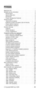
Contents Read this first . . . . . . . . . . . . . . . . Related service information . . . . . . . . . Reset switch . . . . . . . . . . . . . . Service Web site . . . . . . . . . . . . Passwords . . . . . . . . . . . . . . . Power management features . . . . . . . Checkout guide . . . . . . . . . . . . . . . Testing the computer . . . . . . . . . . Detecting system information with PC-Doctor Power system checkout . . . . . . . . . Port replicator checkout . . . . . . . . . Product overview . . . . . . . . .
1100 PC Card slot assembly . . . . . . . . . . 1110 Asset ID RF adapter kit . . . . . . . . . 1120 Sub card . . . . . . . . . . . . . . . . 1130 Guide rail, microphone cable, or TV Out card 1140 CPU card and fan . . . . . . . . . . . . 1150 Modem cable assembly . . . . . . . . . 1160 System board . . . . . . . . . . . . . . 2010 LCD front cover . . . . . . . . . . . . . 2020 LCD Hinges and cables . . . . . . . . . 2030 Inverter card . . . . . . . . . . . . . . Locations . . . . . . . . . . . . . . . . . . .
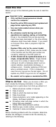
Read this first Read this first Before you go to the checkout guide, be sure to read this section. Important notes Only certified trained personnel should service the computer. Read the entire FRU removal and replacement page before replacing any FRU. Use new nylon-coated screws when you replace FRUs. Be extremely careful during such write operations as copying, saving, or formatting.
Read this first Note for warranty: During the warranty period, the customer may be responsible for repair costs if the computer damage was caused by misuse, accident, modification, unsuitable physical or operating environment, or improper maintenance by the customer. The following list provides some common items that are not covered under warranty and some symptoms that might indicate that the system was subjected to stress beyond normal use.
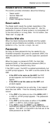
Related service information Related service information This section provides information about the following: “Reset switch” “Service Web site” “Passwords” Power management features Reset switch The Reset switch resets the system (regardless of the microcode status) and forces the power off. Use this pushbutton to power off when power is not completely off or the microcode is in a hung state. For its location, see “Rear view” on page 66.
Related service information Supervisor and hard disk passwords: The supervisor password (PAP) and the hard disk password (HDP) are security features that are used to protect the system and the hard disk data from unauthorized access. No overriding capability is provided. If only a hard disk password is set, you must get the password from its owner in order to run diagnostic tests and perform service.
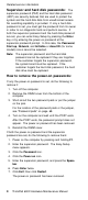
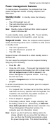
Related service information Power management features To reduce power consumption, the computer has three power management modes: standby, suspend, and hibernation. Standby mode: In standby mode, the following occurs: The LCD backlight turns off. The hard disk drive motor stops. The speaker is muted. Note: Standby mode in Windows 98 is called suspend mode in Windows 95. To enter standby mode, press Fn + F3. To end standby mode and resume normal operation, press any key.
Related service information behavior is independent of the operating system. So, if you have set the low-battery alarm, the computer may not do what you specified. It chooses either your setting or the default setting, whichever is appropriate. Any one of the following events causes the computer to resume operation from suspend mode: The Fn key is pressed. The LCD cover is opened. The ring indicator (RI) is signaled by a serial device or a PC Card device. The power switch is turned on.
Checkout guide The timer conditions are satisfied in suspend mode (for operating systems other than Windows 98). A critically low battery condition occurs and mode is set to Hibernate when battery becomes low. When the power is turned on, the computer leaves hibernation mode and resumes operation. The hibernation file in the boot record on the hard disk drive is read, and system status is restored from the hard disk drive.
Checkout guide Dock the 770 series computer to the docking station. Then start Easy-Setup. To run the test, do as follows: Note: In the following procedure, you can select an item not only with the arrow keys, but also with the TrackPoint. Instead of pressing Enter, click the left button. 1. Insert the PC-Doctor disk into the diskette drive; then power on the computer. If the computer cannot be powered on, go to “Power system checkout” on page 9, and check the power sources.
Checkout guide 4. Run the applicable function test. 5. Follow the instructions on the screen. If there is a problem, PC-Doctor shows some messages. 6. To exit the test, select Quit — Exit Diag. To cancel the test, press Esc.
Checkout guide 4. Check that power is supplied when you power on the computer. 5. Power off the computer. 6. Disconnect the ac adapter and install the charged battery pack. 7. Check that power is supplied by the battery pack when you power on the computer.
Checkout guide Perform operational charging. If the battery status indicator or icon does not turn on, remove the battery pack and let it return to room temperature. Reinstall the battery pack. If the charge indicator or icon still does not turn on, replace the battery pack. If the charge indicator still does not turn on, replace the system board. Then reinstall the battery pack. If the reinstalled battery pack is not charged, go to the next section.
Checkout guide Checking the backup battery: Do the following: 1. Power off the computer, and unplug the ac adapter from it. 2. Turn the computer upside down. 3. Remove the backup battery Note: Removing the backup battery will cause loss of configuration data unless the battery pack is installed and operational. (see “Checking the battery pack” on page 11). 4. Measure the voltage of the backup battery. See the following figure. Wire Voltage (V dc) Red +2.5 to +3.
Product overview Universal serial bus test with the USB parallel test cable Parallel port test with the wrap plug installed on the port replicator 10. If diagnostic errors appear, replace the port replicator or the diskette drive. If the problem remains after the replacement, replace the system board. 11. If power problems appear only when the port replicator is used, replace the port replicator.
Product overview Feature Description Diskette drive (External) 1.44 MB (3-mode), 3.5-inch Hard disk drive 6.0 GB, 2.5-inch, IDE interface 12.0 GB, 2.5-inch, IDE interface CD-ROM/DVD drive 24 x CD-ROM drive DVD drive (6 x DVD) I/O port External monitor Headphone Line-in Microphone Mouse Parallel Port replicator Serial USB Video output port Internal modem 56.
Product overview Status indicators The system status indicators blink green or orange to show the status of the computer. 1 2 3 4 5 6 Symbol Color Meaning .1/Battery Green The battery is fully charged. Orange The battery is charging. Blinking orange The battery needs charging. .2/Suspend mode Green Suspend mode. Blinking green Entering suspend mode. .3/Hard disk in use Orange Data is read from or written to the hard disk drive. .
Product overview Fn key combinations The following table shows the function of each combination of Fn with a function key. The Fn key works independently from the operating system. The operating system obtains the status through the system management interface to control the system. Fn + Description F1 Reserved. F2 Turn the Fuel Gauge display on or off. F3 Turn standby mode on. F4 Turn suspend mode on. F5 Reserved. F6 Reserved. F7 Switch between the LCD and an external monitor.
Symptom-to-FRU error messages Symptom-to-FRU error messages This chapter describes the Symptom-to-FRU error messages. How to use error messages Use the error codes displayed on the screen to diagnose failures. If two or more error codes are displayed, begin the diagnosis with the first one. Whatever caused the first error code can cause false error codes to be displayed. If no error code is displayed, see if the error symptom is listed in the “Symptom-to-FRU index.
Symptom-to-FRU error messages Numeric error codes Symptom or error 10X FRU or action, in sequence 1. System board 101: Interrupt failure. 102: Timer failure. 103: Timer interrupt failure. 104: Protected mode failure. 105: Last 8042 command not accepted. 107: NMI test failure. 108: Timer bus test failure. 109: Low meg-chip select test. 110 System board parity. 1. Go to “Testing the computer” on page 7. 2. DIMM card. 3. If the expansion unit is attached to the computer, detach it. 4. System board.
Symptom-to-FRU error messages Symptom or error FRU or action, in sequence 161 Dead battery. 1. Go to “Checking the backup battery” on page 12. 2. Backup battery. 3. System board. 163 Time and date were not set. 1. Set time and date. 2. System board. 173 Configuration data was lost. 1. Select OK in the error screen; then set the time and date. 2. Backup battery. 3. System board. 174 1. Check device configuration. 2. Hard disk drive assembly. 3. System board. 175, 177, 178 1. System board.
Symptom-to-FRU error messages Symptom or error FRU or action, in sequence 191XX PM initialization error. 1. System board. 192 Fan error. 1. Go to “Testing the computer” on page 7. 2. Measure the voltage of the backup battery. If the voltage is not correct, replace the backup battery. 3. Fan. 4. System board. 193 RF Antenna has been removed. 1. Type the correct supervisor password at the password prompt. 2. Reseat the RF Antenna to the HDD cover. 194 The computer is carried through the portal gate.
Symptom-to-FRU error messages Symptom or error FRU or action, in sequence 301, 303, 304, 305, 3XX 301: Keyboard error. 1. Go to “Testing the computer” on page 7. 2. Keyboard. 3. External numeric keypad. 4. External keyboard. 5. Keyboard and mouse cable. 6. System board. 601, 6XX 601: Diskette drive or controller error. 1. Go to “Testing the computer” on page 7. 2. Diskette drive assembly. 3. Diskette. 4. System board. 602 Diskette read error. 1. Go to “Testing the computer” on page 7. 2. Diskette. 3.
Symptom-to-FRU error messages Symptom or error 861X Pointing device error when TrackPoint is enabled. 8611: System bus error–I/F between 8042 and IPDC. 8612: TrackPoint error. 8613: System board or TrackPoint error. I9990301 I9990302 I9990305 I9990301: Hard disk error. I9990302: Invalid hard disk boot record. I9990305: No bootable device. I9990303 (Bank–2 flash ROM check sum error.) Other codes not listed above. 22 FRU or action, in sequence 1. Go to “Testing the computer” on page 7. 2.
Symptom-to-FRU error messages Beep symptoms Symptom or error FRU or action, in sequence Continuous beeps. 1. System board. One beep and a blank, unreadable, or flashing LCD. 1. Reseat the LCD connector. 2. LCD assembly. 3. System board. One beep, and the message “Unable to access boot source.” 1. Boot device. 2. System board. One long and two short beeps, and a blank or unreadable LCD. 1. System board. 2. LCD assembly.
Symptom-to-FRU error messages Symptom or error No beep during POST, but system runs correctly. FRU or action, in sequence 1. Turn the volume up and check the speaker. 2. Speaker. 3. Sub card. 4. System board. Audio-related symptoms Symptom or error FRU or action, in sequence In OS/2, DOS, or Windows multimedia programs, no sound comes from the computer. (Only system beeps are heard at power-on.) Check that the device driver is installed correctly.
Symptom-to-FRU error messages Symptom or error FRU or action, in sequence The compact disc cannot be read. Make sure that: The compact disc is not dirty. If it is, clean it with a CD-ROM cleaner kit. The compact disc is not defective. If it is, try another compact disc. The compact disc is placed in the tray with the label side up.
Symptom-to-FRU error messages Symptom or error FRU or action, in sequence The CD-ROM does not work. Make sure that: The computer power is turned on and a compact disc is in the CD-ROM drive. The CD-ROM drive connector is firmly connected to the computer. The CD-ROM drive tray is firmly closed. The device drivers are correctly installed. If the CD-ROM drive in the docking station still does not work, do the following: 1. Click on Start. 2.
Symptom-to-FRU error messages Function-related symptoms Symptom or error The system does not suspend or resume when the LCD is closed or opened. FRU or action, in sequence 1. Go to “Suspend mode” on page 5, and check that the computer can enter suspend mode. 2. Boot an operating system and press Fn+F4. If the computer enters suspend mode, suspect that the application program is not working properly. 3. LCD assembly. 4. System board. The battery Fuel Gauge does not go higher than 90%.
Symptom-to-FRU error messages Infrared-related symptoms Symptom or error Unable to communicate using the Infrared (IR) Port. FRU or action, in sequence 1. Make sure the setup for the IR is correct. Use the ThinkPad Configurations utility. 2. Make sure there are no fluorescent lights near the computer. The computer may receive optical noise from the fluorescent light. 3. Run the advanced diagnostic test. If an error occurs and a FRU code is displayed, replace the parts shown by the FRU code.
Symptom-to-FRU error messages LCD-related symptoms Important The TFT LCD for the notebook computer contains many thin-film transistors (TFTs). A small number of dots that are missing, discolored, or always lighted is characteristic of TFT LCD technology, but excessive pixel problems can cause viewing concerns. The LCD should be replaced if the number of missing, discolored, or lighted dots in any background is: XGA (13.
Symptom-to-FRU error messages Symptom or error FRU or action, in sequence In OS/2, DOS, or Windows, the modem does not work. Check that the modem is active. OS/2 and Windows: Click on the Modem icon in the ThinkPad Configuration program. DOS: Run the MWMODEM ON command. PC Card-related symptoms Symptom or error PC Card does not work in either the upper slot or the lower slot. PCMCIA slot pin is damaged. PC Card does not work. FRU or action, in sequence 1. Reseat the PCMCIA slot assembly. 2.
Symptom-to-FRU error messages Power-related symptoms Symptom or error FRU or action, in sequence Power shuts down during operation. 1. Go to “Power system checkout” on page 9. 2. Battery pack. 3. Remove the battery pack and let it cool for 2 hours. 4. System board. 5. Check the power outlet. The system does not power off. (See “Reset switch” on page 3.) 1. Press the power shutdown switch. 2. System board.
Symptom-to-FRU error messages Verify that all attached devices are supported by the computer. Verify that the power supply being used at the time of the failure is operating correctly. (See “Power system checkout” on page 9): 1. Power off the computer. 2. Visually check the attached devices damage. If any problems are found, replace the FRU. 3. Remove or disconnect all of the following devices: a. Non-IBM devices b. Devices attached to the port replicator c. Printer, mouse, and other external devices d.
FRU replacement notices FRU replacement notices This section contains notices for removal and replacement. Read this section carefully before replacing any FRU. Screw notices Loose screws can cause a reliability problem. The IBM ThinkPad computer address this problem with special nylon-coated screws that have the following characteristics: They maintain tight connections. They do not easily come loose, even with shock or vibration. They need additional force to tighten.
FRU replacement notices have a torque screwdriver. Never use a screw that you removed. Use a new one. Make sure the screws are tightened firmly Retaining serial numbers This section includes the following descriptions: “Restoring serial number of the system unit” “Retaining the UUID” Restoring serial number of the system unit: When the computer was manufactured, the EEPROM on the system board was loaded with the serial numbers of the system and all major components.
FRU replacement notices 1. Install the ThinkPad Hardware Maintenance Diskette Version 1.60, and restart the computer. 2. Select 4. Assign UUID from the main menu. A new UUID is created and written. If a valid UUID already exists, it is not overwritten.
FRU removals and replacements FRU removals and replacements This section presents information and drawings for use in removing and replacing a FRU. Be sure to observe the following general rules: 1. Do not try to service the computer unless you have been trained and certified. An untrained person runs the risk of damaging parts. 2. Before replacing any FRU, review “FRU replacement notices” on page 33. 3. Begin by removing any FRUs that have to be removed before the failing FRU.
FRU removals and replacements Attention The system board is sensitive to, and can be damaged by, electrostatic discharge. Establish personal grounding by touching a ground point with one hand before touching these units. You must use an electrostatic discharge (ESD) strap (P/N 6405959) must be used to establish personal grounding.
FRU removals and replacements 1010 Backup battery Caution The backup battery is a lithium battery and can cause a fire, an explosion, or severe burns. Do not recharge it, remove its polarized connector, disassemble it, heat it above 100°C (212°F), incinerate it, or expose its cell contents to water. Dispose of the battery as required by local ordinances or regulations. The use of an incorrect battery can result in ignition or explosion of the battery. Note: Loosen the screw .1/, but do not remove it.
FRU removals and replacements 1020 DIMM 39
FRU removals and replacements 1025 Modem card 40 ThinkPad 600X Hardware Maintenance Manual
FRU removals and replacements 1030 Battery pack Unlock Lock 2 1 41
FRU removals and replacements 1040 Hard disk drive Attention Do not drop or apply any shock to the hard disk drive. The hard disk drive is sensitive to physical shock. Incorrect handling can cause damage and permanent loss of data. Before removing the drive, have the user make a backup copy of all the information on the drive if possible. Never remove the drive while the system is operating or is in suspend mode. 1 3 2 Step Screw (Quantity) Color Torque .
FRU removals and replacements 1050 UltraslimBay device 1 2 When the security screw is installed In step .1/, use a 2.5-mm allen wrench to remove the security screw.
FRU removals and replacements 1060 Keyboard assembly Battery pack (1030) Hard disk drive (1040) UltraslimBay device (1050) 1 2 3 4 Step Screw (Quantity) Color Torque .1/ M2.5 × 19.5 mm, nylon-coated (3) Black 4 kgcm .2/ M2.5 × 16 mm, nylon-coated (2) Black 4 kgcm .3/ M2.5 × 4.8 mm, nylon-coated (1) Black 4 kgcm .4/ M2.5 × 3 mm, nylon-coated (4) Yellow 4 kgcm Now turn the computer right side up.
FRU removals and replacements 5 Step Screw (Quantity) Color Torque .5/ M2.5 × 4.
FRU removals and replacements 8 46 ThinkPad 600X Hardware Maintenance Manual
FRU removals and replacements 1070 Keyboard Battery pack (1030) Hard disk drive (1040) UltraslimBay device (1050) Keyboard assembly (1060) Note: In step .1/, remove the insulator gently for it is reused. 2 3 4 1 2 Bottom view 4 Step Screw (Quantity) Color Torque .2/ M2.
FRU removals and replacements 1080 Speakers Battery pack (1030) Hard disk drive (1040) UltraslimBay device (1050) Keyboard assembly (1060) Note: In step .1/, remove the insulator on the left speaker. 2 3 2 4 1 4 Bottom view Step Screw (Quantity) Color Torque .2/ M2.
FRU removals and replacements Cable route: When replacing the right speaker, see the following figure for its cable route.
FRU removals and replacements 1085 Speaker cable Battery pack (1030) Hard disk drive (1040) UltraslimBay device (1050) Keyboard assembly (1060) Note: In step .1/, remove the insulator on the left speaker. 2 4 1 3 Bottom view Step Screw (Quantity) Color Torque .2/ M2.
FRU removals and replacements 1090 LCD assembly Battery pack (1030) Hard disk drive (1040) UltraslimBay device (1050) Keyboard assembly (1060) 1 3 2 4 3 5 6 7 Step Screw (Quantity) Color Torque .1/ M2.5 × 4.8 mm, nylon-coated (4) Black 4 kgcm .3/ M2.5 × 4.8 mm, nylon-coated (4) Black 4 kgcm .4/ M2.5 × 4.
FRU removals and replacements 1100 PC Card slot assembly Battery pack (1030) Hard disk drive (1040) UltraslimBay device (1050) Keyboard assembly (1060) 2 1 Connector 3 Step Screw (Quantity) Color Torque .1/ M2.0 × 9.5 mm, nylon-coated (4) Black 2.
FRU removals and replacements 1110 Asset ID RF adapter kit Battery pack (1030) Hard disk drive (1040) UltraslimBay device (1050) Keyboard assembly (1060) 53
FRU removals and replacements 1120 Sub card Battery pack (1030) Hard disk drive (1040) UltraslimBay device (1050) Keyboard assembly (1060) LCD assembly (1090) 2 Cennector 3 1 Step Screw (Quantity) Color Torque .2/ M2.5 × 4.
FRU removals and replacements 1130 Guide rail, microphone cable, or TV Out card Battery pack (1030) Hard disk drive (1040) UltraslimBay device (1050) Keyboard assembly (1060) Sub card (1120) Step Screw (Quantity) Color Torque .4/ M2.0 × 9.5 mm, nylon-coated (1) Black 2.5 kgcm .5/ M2.5 × 4.8 mm, nylon-coated (2) Black 4 kgcm .7/ M2.5 × 7 mm, nylon-coated (1) Yellow 4 kgcm When replacing: Make sure the connector on the TV Out card is firmly connected.
FRU removals and replacements 1140 CPU card and fan Battery pack (1030) Hard disk drive (1040) UltraslimBay device (1050) Keyboard assembly (1060) 3 2 3 1 Cennector 4 Step Screw (Quantity) Color Torque .1/ M2.0 × 9.5 mm, nylon-coated (1) Black 2.5 kgcm .3/ M2.0 × 9.5 mm, nylon-coated (4) Black 2.
FRU removals and replacements 5 Fan 6 CPU card Step Screw (Quantity) Color Torque .5/ M2.0 × 4.0 mm, nylon-coated (2) Black 2.5 kgcm When replacing: When you replace the CPU card, press it only at the places indicated in the figure. Press both sides at the same time. Do not press only one side or any other part of the card; to do so might damage it.
FRU removals and replacements 1150 Modem cable assembly Battery pack (1030) Hard disk drive (1040) UltraslimBay device (1050) Keyboard assembly (1060) 1 2 3 Step Screw (Quantity) Color Torque .1/ M2.5 × 4.
FRU removals and replacements Cable route: When replacing the modem cable, see the preceding figure for its cable route. Step Screw (Quantity) Color Torque .4/ M2.5 × 4.
FRU removals and replacements 1160 System board Backup battery (1010) DIMM (1020) Modem card (1025) Battery pack (1030) Hard disk drive (1040) UltraslimBay device (1050) Keyboard assembly (1060) LCD assembly (1090) PC Card slot assembly (1100) Sub card (1120) TV Out card (1130) CPU card and fan (1140) Modem cable assembly (1150) 2 3 4 1 Step Screw (Quantity) Color Torque .1/ M2.5 × 4.8 mm, nylon-coated (3) Black 4 kgcm .2/ M2.5 × 4.
FRU removals and replacements 2010 LCD front cover Battery pack (1030) Hard disk drive (1040) UltraslimBay device (1050) Keyboard assembly (1060) LCD assembly (1090) Important The TFT LCD for the notebook computer contains many thin-film transistors (TFTs). A small number of dots that are missing, discolored, or always lighted is characteristic of TFT LCD technology, but excessive pixel problems can cause viewing concerns.
FRU removals and replacements 2020 LCD Hinges and cables Battery pack (1030) Hard disk drive (1040) UltraslimBay device (1050) Keyboard assembly (1060) LCD Assembly (1090) LCD front cover (2010) (Continued) 62 ThinkPad 600X Hardware Maintenance Manual
FRU removals and replacements When you replace the cables, make sure they are not caught by the LCD panel.
FRU removals and replacements 2030 Inverter card Battery pack (1030) Hard disk drive (1040) UltraslimBay device (1050) Keyboard assembly (1060) LCD assembly (1090) LCD front cover (2010) 3 1 2 Step Screw (Quantity) Color Torque .1/ M2.5 × 4.
Locations Locations Front view .1/ .2/ .3/ .4/ .5/ .6/ .7/ .8/ .9/ .1ð/ .11/ .12/ .13/ .14/ LCD panel Brightness control Built-in microphone PC Card slots PC Card eject button Infrared port Headphone jack Line-in jack Microphone jack External diskette drive Diskette-eject button Video-out connector LCD latch UltraslimBay Note: The UltraslimBay accepts storage devices, such as a DVD drive or a CD-ROM. .15/ .16/ .17/ .18/ .19/ .
Locations Rear view .1/ .2/ .3/ .4/ .5/ .6/ .7/ .8/ .9/ .1ð/ .
Locations Bottom view .1/ .2/ .3/ .4/ .5/ .6/ .7/ .8/ .9/ .
Locations Password pads 68 ThinkPad 600X Hardware Maintenance Manual
Parts list Parts list 69
Parts list No. FRU 1 LCD unit (see “LCD FRU” on page 73.
Parts list No. FRU P/N 20 Cover, modem 08K6031 21 Modem card 08K3429 22 Fan assembly 08K5909 Fan assembly, for 2465-5Fx and -9Fx 08K6290 23 Keyboard bracket (see System miscellaneous parts) 24 TrackPoint III cap 84G6536 25 Speaker 02K4897 Cable, diskette drive 05K2844 Doors 05K4828 Diskette drive I/O right I/O left USB TV out card 10L1352 Screw kit All nylon-coated screws: 05K4841 M2 x 4 mm, pan head (5) M2 x 9 mm, flat head (10) M2.
Parts list Keyboard 72 Language P/N Arabic 02K4837 Belgian 02K4801 Czech 02K4839 Canadian French 02K4788 Danish 02K4794 Dutch 02K4791 French 02K4790 German 02K4789 Greek 02K4843 Hungary 02K4841 Hebrew 02K4835 Italian 02K4795 Japanese 02K4786 Korean 02K4800 Latin American Spanish 02K4799 Norwegian 02K4793 Portuguese 02K4798 Russian 02K4833 Spanish 02K4796 Swedish or Finnish 02K4792 Swiss 02K4797 Taiwan 02K4803 Turkish 02K4802 U.K. English 02K4787 U.S.
Parts list LCD FRU 13.3-inch XGA TFT No.
Parts list . No.
Parts list Option list AC adapter (56W, Sanken) 02K6555 AC adapter for Japan 02K6554 AC adapter (56W, ASTEC) 02K6557 AC adapter for Japan (56W, ASTEC) 02K6556 Battery attachment 02K6501 Battery charger 11J9003 Blank bezel for bay 05K4842 Carrying case, for CD-ROM 05K4843 Enhanced video cable 05K2821 External diskette drive case 05K6187 Modem kit for Austria 22L1863 for Australia 22L1939 for Belgium 22L1861 for Brazil 22L1871 for Cyprus 22L1887 for Denmark 22L1879 for France
Parts list for Switzerland 22L1882 for Turkey 22L1884 for U.K. 22L1876 for Vietnam 22L1875 Secondary battery 02K6505 Slim Bay adapter 05K5858 SelectaBase 600 12J2480 SuperDisk (LS-120) UltraslimBay drive 20L1922 Telephone cable 05K2707 UltraslimBay HDD adapter 05K5338 24X-10X IDE CD-ROM drive 12J2471 6.
Parts list Power cords: IBM power cords for a specific country are usually available only in that country: For 2-pin power cords: Used in these countries P/N Japan 13H5273 Argentina 36L8870 For 3-pin power cords: Used in these countries P/N Argentina 36L8867 People's Republic of China (other than Hong Kong) 76H3514 Argentina, Australia, New Zealand, Papua New Guinea, Paraguay, Uruguay 76H3516 Aruba, Bahamas, Barbados, Bermuda, Bolivia, Brazil, Canada, Cayman Islands, Colombia, Costa Rica, C
Notices References in this publication to IBM products, programs, or services do not imply that IBM intends to make these available in all countries in which IBM operates. Any reference to an IBM product, program, or service is not intended to state or imply that only that IBM product, program, or service may be used. Any functionally equivalent product, program, or service that does not infringe any of the intellectual property rights of IBM may be used instead of the IBM product, program, or service.