4560SLX Tape Library User’s Guide Important: To maintain your new IBM 4560SLX Tape Library at peak performance and reliability, follow the maintenance procedures described in Chapter 5, “Maintenance” on page 43. Failure to do so may impact your product warranty.
4560SLX Tape Library User’s Guide
Note: Before using this information and the product it supports, read the information in Appendix E, “Warranty information” on page 99 and Appendix F, “Notices” on page 111. First Edition (August 2002) © Copyright International Business Machines Corporation 2002. All rights reserved. US Government Users Restricted Rights – Use, duplication or disclosure restricted by GSA ADP Schedule Contract with IBM Corp.
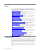
Contents Safety . . . . . . . . . . . . . . . v Preface . . . . . . . . . . . . . . vii Product Registration . . . . . . . . . . . vii Chapter 1. Introduction . . . . . . . . 1 Contents . . . . . . . . Configurations. . . . . . Library interfaces . . . . . Front panel . . . . . . . Magazine doors . . . . . Magazines . . . . . . . Mail slots . . . . . . . Power supply . . . . . . Tape drives . . . . . . . Library controller board . . Robotics . . . . . . . . Multi-module library systems. . . .
Cabling considerations for fail-over operation . Fail-over initiation . . . . . . . . . . Restoring normal operation . . . . . . . . 88 . 88 . 89 Appendix C. Specifications . . . . . . 91 Hardware . . . . . . . Environmental . . . . . Safety . . . . . . . Electromagnetic emissions Electrostatic discharge . . Temperature, humidity, and Shock . . . . . . . Vibration . . . . . . Primary power . . . . . Voltage limits . . . . . Frequency limits . . . . Power requirements . . Sag/Surge protection . .
Safety Before installing this product, read the Safety Information. Antes de instalar este produto, leia as Informações de Segurança. Pred instalací tohoto produktu si prectete prírucku bezpecnostních instrukcí. Læs sikkerhedsforskrifterne, før du installerer dette produkt. Ennen kuin asennat tämän tuotteen, lue turvaohjeet kohdasta Safety Information. Avant d’installer ce produit, lisez les consignes de sécurité. Vor der Installation dieses Produkts die Sicherheitshinweise lesen.
vi 4560SLX Tape Library: User’s Guide
Preface This manual provides step-by-step installation instructions and information required for ongoing use and maintenance of the IBM® 4560SLX Tape Library. This manual is written for the installer and user of this equipment. The following information is contained in this manual: v Chapter 1, “Introduction” provides an introduction to the 4560SLX Tape Library, along with a brief description of the library parts.
viii 4560SLX Tape Library: User’s Guide
Chapter 1. Introduction The IBM 4560SLX Tape Library is a backup and restore solution for high-end xSeries™ servers. The library provides many features and functions not normally found in similarly classed products. Please read this document in its entirety before attempting to install or use the library. This chapter provides an introduction to the 4560SLX Tape Library.
– Fibre Channel Option (FCO) card – Interface cables (two) – Fibre Option User Guide v SDLT magazine option (Part number: 59P6661) – Left magazine – Right magazine – Barcode pack – 4560SLX Tape Library Quick Installation Guide v LTO magazine option (Part number: 59P6659) – Left magazine – Right magazine – Barcode pack – 4560SLX Tape Library Quick Installation Guide v Cartridge elevator option (Part number: 59P6662) – Ethernet router – Base mechanism – Interconnect cables (three) – 4560SLX Tape Library Quick
1 2 3 4 5 Left magazine door Internal viewing window Touch screen Library status LED Right magazine door Figure 1. Library front panel Table 1 describes the different indicator settings of the library status LED. Table 1. Library front panel indicators Library Indicators Solid Green The library is operating correctly under normal conditions. Flashing Green The library is operating correctly.
Magazines The 4560SLX Tape Library contains two removable tape cartridge magazines that are accessible through the magazine doors as shown in Figure 3. The magazine doors are opened using the touch screen. Note: The magazine must match the installed tape drive. For example, an LTO magazine should be installed on an LTO drive and an SDLT magazine should be installed on an SDLT drive. 1 2 Left magazine with integrated mail slot Right magazine Figure 3.
Power supply The power supply is accessible from the rear of the library as shown in Figure 5. These auto-ranging power supplies are capable of using any nominal ac voltage between 100 and 240 V power at 50 Hz or 60 Hz. Power to the library is supplied through the cord on the rear panel of the power supply. Library power is controlled from the touch screen. However, a manual power disconnect switch, located on the rear of the power supply, can also be used.
Tape drives The 4560SLX Tape Library supports a 0-drive, 1-drive, or 2-drive configuration as shown in Figure 6. All inactive tape drives are hot-swap capable. SCSI I/O is accomplished through two VHDCI-series 68-pin SCSI connectors located on the rear of the library directly under each tape drive as shown in Figure 7. 1 2 Tape drive 1 Tape drive 2 Figure 6. Tape drive locations 1 2 3 Drive 1 Drive 2 bay VHDCI 68-pin connectors Figure 7.
1 2 Rear access card cage Library controller board Figure 8. Library controller adapter and PCI slots The library controller board contains a single microprocessor and associated logic devices to control all robotics operations and manage overall library functions. The microprocessor enables the SCSI interface between the library and the host system, including Web TLC (Total Library Control). Web TLC is built into the library controller board.
1 2 Bar code reader Cartridge shuttle assembly Figure 9. Library robotics Multi-module library systems The 4560SLX Tape Library is an expandable tape library that can be configured in a variety of module and drive combinations. The drives are mounted in a removable drive shoe that enables easy installation and removal. Therefore, a failed drive can be swapped without the server or library power needing to be cycled.
library control software as a single library. For multi-module applications, the top library module becomes the primary master module and all other libraries become slave modules. The library robotics pick up and place tape cartridges into an elevator so that individual tapes can be passed up or down between libraries in a multi-unit library configuration. The 4560SLX Tape Library supports fail-over protection for multi-unit library configurations.
10 4560SLX Tape Library: User’s Guide
Chapter 2. Installation This chapter explains how to install the 4560SLX Tape Library. Sections in this chapter include: v Setup v SCSI cable configurations v Turning on the library Setup Before rack mounting the library, make sure there is adequate space available in the rack. See “Installation considerations” on page 96, for considerations relating to multi-unit rack-mounted environments. Note: When lifting the library use a mechanical lifter or a two person minimum.
1 2 3 4 5 6 7 Inner slide member Hex screw (eight M4 x 8mm) Front mounting bracket Rear mounting bracket Outer slide member Middle slide member Screw, flat washer, lock washer, nut (eight sets) 8 9 10 11 12 13 14 Clip or cage nut (eight 8-32) Screw (eight 10-32 x 5/8) Clip or cage nut (two 10-32) Ball bearing slide member Sticker Thumbscrew (two 10-32) Door latch insert Note: If you are installing the library on the IBM Netbay42 Enterprise rack, clip nuts ( 8 and 10 ) are p
Attaching the slide members to the rack To attach the slide members to the rack, complete the following procedure: 1. Attach the front (shorter) and rear (longer) mounting brackets to the outer and middle slide members as shown in Figure 12. IMPORTANT: Fully tighten the front mounting bracket screws. Leave the rear mounting bracket screws “finger tight” to prevent binding when mounting the library module. Once the distance between rails is set, the screws should be fully tightened.
3. Push the middle slide member as far as possible to the front of the slide member assembly. Installing a library in the rack To install a library in the rack, complete the following procedure: 1. Install a clip or cage nut on each side of the front vertical rails as shown in Figure 14. 1 2 Clip or cage nut Vertical member mounting holes Figure 14. Installing the library module 2. Lighten the library module by removing the drives. 3.
Figure 15. Retaining screws 8. Remove the door latch insert (the red tab located on the front panel). 9. Re-insert the drives. 10. Fully tighten the rear mounting bracket screws. 11. Close the doors. 12. Connect the ac power supply to the library. SCSI cable configurations The 4560SLX Tape Library supports multiple SCSI cable configurations on single and dual host systems. SCSI interface connectors The library should be attached to a low voltage differential SCSI bus.
SCSI configuration Your specific configuration will depend on the speed of your host and SCSI controller. The library uses high performance tape drives. The tape drive performance might be degraded if you attach too many drives to a single SCSI host controller. One tape drive on a single host system Figure 16 shows a typical SCSI cable configuration for a library with one tape drive (drive 1) installed. 1 2 3 SCSI terminator To library controller card To host system Figure 16.
1 2 SCSI terminator To library controller card 3 4 Jumper cable To host system Figure 17. Two tape drives single host Two tape drives on a dual host system Figure 18 shows a typical SCSI cable configuration for a library with two tape drives installed using a dual host system. 1 2 3 SCSI terminator To library controller card To host (drive 1) 4 5 To host (drive 2) SCSI terminator Figure 18. Two tape drives dual host Chapter 2.
Multiple libraries on a single host system Figure 19 shows a typical SCSI cable configuration for a multi-unit library with a varying number of drives using a single host system. 1 1 2 To host system SCSI terminator Figure 19.
Multiple libraries on a dual host system Figure 20 shows a typical SCSI cable configuration for a library with multiple libraries and tape drives installed using a dual host system. 1 1 2 2 3 4 5 6 7 WAN To host system SCSI terminators Figure 20. Dual host multi-unit system Turning on your library Use the following instructions to apply power to the library: 1. Connect the supplied power cord to the ac receptacle located on the back of the library module as shown in Figure 21 on page 20.
1 2 3 Power cord Power switch Touch screen Figure 21. Powering library module 2. Toggle the power switch to on “|”. 3. Press the touch screen to activate the display. When power is first applied to the libraries, a series of Power-On Self Test (POST) diagnostics are performed. After the POST completes, the Initialization screen will appear. 4. Select Continue. The library default screen will display.
Chapter 3. Library configuration The library provides several configuration options to support a variety of applications and platforms. The settings for each of the available options are stored in non-volatile memory in the library. For most applications, you do not have to change the default settings. However, if you need to change the configuration, use the instructions provided in the following sections. If you are uncertain whether you need to change a setting, contact your authorized service provider.
Figure 23. SCSI ID selection screen 5. Select the button next to the SCSI ID you want to set. The screen will display the current setting as shown in Figure 24. Figure 24. SCSI ID editing screen 6. Enter a new value for the SCSI ID. This places your request in the New data field. 7. Select Save. A confirmation screen appears on the display as shown in Figure 25. Figure 25. SCSI ID Confirmation screen 8. Select OK to confirm.
Figure 26. Drive 1 Bus 3 Data Field screen 9. Press the Back button to return to the Main menu screen. Repeat this procedure to set any remaining SCSI IDs. Setting up reserved tape cartridge slots You might want to reserve tape cartridge slots to meet licensing requirements or dedicate them as cleaning slots. Standard tape cartridge slots are numbered from the front of the magazine to the rear as shown in Figure 27 on page 24.
1 2 #12 #25 #11 #24 #10 #23 #9 #22 #8 #21 #7 #20 #6 #19 #5 #18 #4 #17 #3 #16 #2 #15 #1 #14 MAIL SLOT #13 Reserved slot #1 Mail slot (left magazine only) Figure 27. Slot numbering To reserve a slot, complete the following procedure: 1. From the Menu screen, select the Library option from the Edit Options area. 2. From the Library options screen, press the down arrow to scroll to the screen that contains the Total Reserved Slots option as shown in Figure 28. Figure 28.
Figure 29. Reserved slots numeric keypad 4. Enter a new value and select Save. A confirmation screen appears on the display as shown in Figure 30. Figure 30. Total Reserved Slots Confirmation screen 5. Press the Back button until you return to the Main menu screen. Your change will take effect the next time you boot the library. Chapter 3.
26 4560SLX Tape Library: User’s Guide
Chapter 4. Operation This chapter describes how to operate the 4560SLX Tape Library. Using the touch screen The touch screen enables you to set up and configure the library.
Figure 32. Mail Slot Access screen Note: In a scaled multi-module library system, selecting the Mail Slot Access button on the master library touch screen displays the mail slots of all the libraries in the stack. This is the only way to access the mailslots of the other libraries. Magazine Access Select this option to display the Magazine Access screen as shown in Figure 33. The Magazine Access option enables you to access the magazine doors for tape cartridge placement or removal.
Figure 34. Move Media screen To move a cartridge, complete the following procedure: 1. Touch the Source box or Source Element Type from the Move Media screen. The Source box will change from gray to an active state as shown in Figure 35. Figure 35. Move Media screen (source) 2. From the Source Element Type area, select the element type you want to move. Drive 2 is used for this example. 3. Touch the Destination box on the Move Media screen.
option is displayed in the Destination box. For example, touching Slot three times displays Slot 3 in the Destination box. 5. Select the Execute Move button. The library robotics moves the cartridge to the destination you selected. LCD contrast controls This option enables you to increase or decrease the contrast of the LCD display. Incremental steps are set by adjusting the LCD contrast controls using the up and down arrows from the upper right corner of the library default screen.
Figure 38. View Library Options screen (initial screen) Table 2 describes the available Library options. Table 2. Library options Option Description Library Stays Offline After Power-up Initialization The library does not go online after power-up initialization. You must select the online option from the menu screen on the touch screen. The default is disabled. Auto Power-up an Installed Drive This option enables a tape drive to be automatically powered up after replacing a tape drive.
Table 2. Library options (continued) Option Description Barcode Label Size This option enables you to limit the maximum number of characters of the bar code label. Possible settings are 1 through 8. The default is 8. Barcode Label Alignment This option enables you to specify the alignment of a bar code label. The options are left or right. When used in conjunction with the label size option, this option strips unwanted trailing characters (left alignment) or leading characters (right alignment).
Table 3. SCSI configuration options (continued) Definition Option and default description Default value Library SCSI Bus Parity This option enables you to set the library robotics SCSI bus parity checking. Enabled SCSI Mode This option defines the loader as SCSI-2 or SCSI-3. SCSI-3 Mailslot access This option defines when the mailslot is accessible.
Table 3. SCSI configuration options (continued) Definition Option and default description Default value TapeAlert Mode This option enables you to specify the conditions for logging and reporting the following tape alert data options: Logging Disabled v Logging Disabled: Inhibits the logging feature. v No Exceptions: Prohibits the library from reporting information exceptions. v Generate Unit Attention: Reports information exceptions with a Unit Attention sense key and an ASC/ASCQ of 5D/00.
Figure 40. View Network Options screen Table 4 describes the available Network options. Table 4. Network configuration options Definition Option and default description Default value IP Address Determination This option enables you to set the way an IP address is determined. The possible choices are: Obtain An IP Address From a DHCP Server and User Specified IP Address. Obtain An IP Address From a DHCP Server Private IP Base Address This option enables you to specify a private IP base 92.168.1.
Figure 41. View Library Info screen Cartridge Map: This option provides a visual indication of all library drives, mail slots and magazine slots, including whether there is a cartridge present and corresponding barcode label, if available. Figure 42.
Figure 43. Security Level screen Table 5. Security level options Security level Access User Level 1 Mail slot access only User Level 2 Mail slot and magazine access only Service User and Service menus Factory User, Service, and Factory menus Edit Options The Edit Options area contains the following screens: v Library v SCSI v Network v Passwords Library: This option enables you to define the library options used to configure the library for your specific needs.
Figure 45. Edit SCSI Options screen Network: This option enables you to define the network options used to configure the library for your specific needs as shown in Figure 46. For a description of the available network options, see Table 4 on page 35. Figure 46. Edit Network Options screen Passwords: This option enables you to define the password options used to configure the library for your specific needs as shown in Figure 47 on page 39. The Password screen offers three levels of security.
Figure 47. Edit Passwords Options screen Each password is represented by four decimal digits that are stored in NVRAM (non-volatile memory) in a range of 0001 to 9999. 0000 is used to disable password verification for that level. Enabling a password causes all disabled higher levels to also be enabled to that value. As a result, prior to accessing a higher level operation, you are prompted first to enter the higher level password.
Figure 48. Status screen Power This option initiates a library power-down operation. Figure 49 shows the confirmation screen that is displayed when this option is selected. The library moves the shuttle assembly to the parked position before powering down. Figure 49. Power Down Initiation screen Using tape cartridges This section describes how to remove magazines, insert cartridges into a magazine, use the mail slot, and use bar codes.
1 2 Left magazine Right magazine Figure 50. Removing tape cartridge magazines Inserting cartridges into a magazine A full magazine is shown in Figure 51. Note that the lowest numbered tape cartridge slot is the one closest to the front of the magazine. Insert tape cartridges so that the bar code labels are facing outward. Note: Handle and store tape cartridges in a clean and dust-free environment.
magazine door for mail slot access. After opening the left magazine door, pivot the mail slot forward to insert a tape cartridge as shown in Figure 52. IMPORTANT: The mail slot must be enabled (factory default) using the Mail Slot Mode option from the Edit Library Options menu. For more information on Library options, see Table 2 on page 31. 1 2 Mail slot Tape cartridge Figure 52. Left magazine mail slot Bar code labels Sample bar code labels are included with your purchase.
Chapter 5. Maintenance This chapter describes how to replace and run cleaning cartridges in the 4560SLX Tape Library. Note: Only qualified service technicians should perform the other menu options contained in the Maintenance submenu.
Manually running a cleaning cartridge You can manually run a cleaning cartridge from three locations: v The mail slot - Running a cleaning cartridge from this location does not require a magazine to be removed, a data cartridge slot to be used, or a cleaning cartridge slot to be reserved. v A data cartridge slot - Running a cleaning cartridge from this location requires a magazine to be removed so that a cleaning cartridge can be inserted in a data cartridge slot.
1. Reserve the cleaning cartridge slot. For more information, see “Setting up reserved tape cartridge slots” on page 23. 2. Install a cleaning cartridge in the reserved slot. 3. Select the Clean Drive menu option from the Maintenance submenu on the Menu screen. The Source window defaults to the cleaning slot (cleaning slot 0). 4. Select Cleaning. If the default entry is not the tape drive to be cleaned, select Drive in the Destination Element Type box to sequence through the available tape drive choices.
11. Select Destination and then select Cleaning Slot in the Destination Element Type box. 12. Select Execute Move to put the new cleaning cartridge in the reserved slot.
Chapter 6. Troubleshooting The following information might be useful if you experience problems using the 4560SLX Tape Library. Platform problems Incorrectly installing or configuring the 4560SLX Tape Drive can cause platform problems. In this occurs, the library appears to be operating normally, but no data can be interchanged. An error code might be displayed on the touch screen. To identify this type of problem, check your installation and configuration setup.
TROUBLESHOOTING AND ERROR RECOVERY ERROR, FAULT, MALFUNCTION Determine Suspected Error Type PLATFORM No FSC displayed. Normal front panel operation GENERAL DRIVE FSC and ERP displayed on touch screen Cycle the power to the library Follow the ERP on touch screen Retry Find FSC in Table 7 Check configuration (see Chapter 3) Follow the ERP in Table 6 Call Technical Support Call Technical Support CARTRIDGE ERROR FSC might be displayed Cartridge will not eject Normal operation impossible Figure 54.
Fault symptom codes (FSCs) Table 7 lists the FSCs and their related ERPs that might be displayed on the touch screen. If an FSC continues, report it to IBM technical support. Table 7.
Table 7.
Table 7.
Table 7.
Table 7. Fault symptom codes (continued) Message FSC ERP Invalid comm. get attempt A005 C,G Comm initialization error A006 C,G Put of a NULL comm A007 C,G Msg contains no comm A008 C,G Comm return address is unknown A009 C,G Note: If an error message is displayed that is not included in Table 7, write down the fault code number and follow the recovery procedure. If the same error occurs again, call IBM technical support. Chapter 6.
54 4560SLX Tape Library: User’s Guide
Chapter 7. Using the NeoCenter utility The NeoCenter utility enables you to configure the unit using the Windows® interface.
An upload process screen is displayed for a moment and then the Configure dialog box appears: Figure 55. Configure dialog box - IP addresses 3. Select the IP Addresses tab. 4. Set the IP addresses by doing one of the following: v Select the check box if you want the addresses to be set by a Dynamic Host Configuration Protocol (DHCP) or BootP server. v Specify the addresses individually. 5. Click OK to save the settings.
2. On the Configure screen, select the Access tab. The Access tab panel is displayed. 3. Place the text cursor into a level field and type in the password. 4. Enable or disable Level 2 access. 5. Enter the library name. 6. Click OK to save the settings. Note: The Access tab panel permits you to specify a familiar, mnemonic name for your library. This name will be displayed on many pages of your Web TLC site.
Setting SCSI parameters 1. Establish communications with the library. 2. On the Configure Library screen, click the SCSI Parameters tab. The SCSI Parameters tab panel is displayed. 3. Click OK to save the settings. For a complete description of the above selectable options, including default options, see Chapter 3, “Library configuration” on page 21. Setting the SCSI identification 1. Establish communications with the library. 2. On the Configure Library screen, click the SCSI Identification tab.
Figure 56. Upload Data From Library prompt 3. Click the radio button for System Trace or Non-Volatile Trace. 4. Use the Browse button to select a network destination for the uploaded binary file. The default file name appears in the Binary File field at the end of the network path. 5. To create a text version of the file, select the Post-Process Upload Data check box. 6. Use the associated Browse button to select NexGen.tdb in the Database File field.
Downloading data The library firmware is resident in flash memory; however, IBM periodically updates this code. You can find the latest firmware files by searching on ″4560SLX″ on the http://www.pc.ibm.com/support IBM Web site. The configuration utility enables you to remotely download flash image files that contain the updated firmware. The download process takes place in two stages. First, the data is downloaded into RAM and is verified; then, it is programmed into the flash memory.
Rebooting the library To 1. 2. 3. reboot the library, complete the following procedure: Establish communications with the library. From the Diag menu, select the Reboot NeoCenter option. Click Yes. 4. Click OK. Chapter 7.
62 4560SLX Tape Library: User’s Guide
Chapter 8. Web TLC Web TLC (Total Library Control) is a remote interface device built into your 4560SLX Tape Library that enables you to monitor and control your automated tape library. Web TLC enables you to view overall status and provides a control panel for making adjustments and viewing details down to the cartridge level. Web TLC hosts a dedicated, protected Internet site that displays a graphical representation of your library.
Serial Configuration Cable Hub Figure 59. Local area network In order to use Web TLC, you must have the following: v A 10 BaseT Ethernet network v A dedicated IP address (either Internet or local) v A host computer with COM port (initial setup and alternative maintenance procedures only) v Access to your network v A web browser installed on your computer (either Microsoft Internet Explorer 3.0 or higher or Netscape 3.
Figure 60. Web TLC login prompt 2. Enter your password in the appropriate field and click Login. The Web TLC Control Panel page appears with the Status screen displayed. Figure 61. Web TLC control panel Status Click the Status button to view itemized status information for the library and for each drive. You can configure two browser settings from this screen: v Auto refresh: off / 1 min / 2 min / 5 min Auto refresh setting ensures that the status of your library displayed on the browser remains valid.
To move a selected cartridge using Web TCL, complete the following procedure: 1. Specify the source slot and destination. 2. Click the Execute the move button. A screen is displayed notifying the user that selecting confirm will cause the library to go offline during the move media operation. 3. Click Confirm to proceed with the move. Setup Click Setup to set various configuration options. Select one of the configuration options from the menu to view or change parameters.
Appendix A. Adding a tape drive This appendix explains how to add a tape drive to the library. See Chapter 1, “Introduction” for a list of tape drives supported by the library. To add a tape drive, complete the following procedure: 1. Unpack the tape drive and inspect it for any damage. If the tape drive has been damaged, return it to IBM for a replacement. Note: With a blank panel or tape drive removed, there is access to moving parts. DO NOT reach into open cavities. 2.
Figure 63. Installing a tape drive 4. Secure the tape drive to the library using the two thumbscrews. 5. Configure the tape drive using the touch screen.
Appendix B. Adding a library module The 4560SLX architecture is uniquely suited to growing storage needs. It enables the robotics in the 4560SLX Tape Library to exchange cartridges by means of a pass-through cartridge elevator, integrating the robotics of each individual module into a single high-performance library robotics system. The 4560SLX Tape Library can be modified by adding modules and cartridge elevators. Add drives to speed performance or magazine space for greater capacity.
The cartridge elevator is composed of a 10U motor drive assembly with extensions equal to the combined heights of the number of modules installed in the rack. You will need to install an additional extension section and timing belt with each additional library you install.
1 1 2 3 4 5 6 2 3 4 5 6 7 WAN Mounting holes 10BaseT connection ports Host port COM port (factory use only) Power switch ac power Figure 64. Cartridge elevator router 2. Position the router at the top rear of the rack to locate the appropriate mounting holes in the rack rails. 3. Install the four captive fasteners into the rack rails. 4. Mount the router using the four screws (10-32x 1/2 P.H.). Do not apply power or connect any cables. 5.
Figure 65. Cartridge elevator router installed Installing the cartridge elevator To install the cartridge elevator, complete the following procedure: Note: The following procedure assumes that the modules have been prepared for rack-mount installation or are installed in a rack. 1. Ensure that the router is mounted at the top of the rack. 2. If modules are rack-mounted, verify that all units are powered down and the power cords are removed.
Figure 66. Drive shoe and blank panel removal Note: With a blank panel or tape drive removed, there is access to moving parts. DO NOT reach into open cavities. a. Loosen the captive retainer screws at the top center and lower left of the drive module. b. Pull straight back on the drive shoe handle to remove the drive. Some effort will be required to overcome the initial resistance of unplugging the module from the receiver. c.
Figure 67. Cover plate removal 5. Install all of the modules in the equipment rack. 6. Slide each of the 4560SLX Tape Libraries a few inches forward, starting below the top (master) library module. When installing the cartridge elevator assembly, work from top to bottom of the library assembly. This eases alignment with less binding of the inner guide pins.
Figure 68. Cartridge elevator (two units) installed 11. Replace drive 2 or the blank cover to all modules. If replacing a drive, repeat the procedure below for each module. a. Fully support the drive shoe assembly while starting it into the receiver, being careful not to damage the drive load handle. b. Push the drive shoe assembly slowly into the receiver until it seats against the back of the library. c. Tighten the two captive retainer screws to secure the module to the library. d.
v Tie bars (to connect extensions) v Install hardware The following are required tools for the cartridge elevator: v #2 Phillips, stubby, or right-angle screwdriver v Flat-blade screwdriver v 0.05 in. allen wrench v Scissors or knife (for sizing the belt) Figure 69 shows a typical 10U cartridge elevator assembly. The motor drive section always goes on top, and the base section with the idler pulley always goes on the bottom.
Figure 70. Cartridge elevator bottom plate 2. Slide the elevator car to the top of the primary chassis. The elevator car is now positioned over the belt block bracket access cutout next to the PCB and drive motor. Figure 71. Cartridge elevator media elevator car 3. On the tensioner ramp/idler pulley base of the primary chassis, compress the springs until the holes in the tensioner ramp are aligned with the holes in the base of the tensioner, and insert a 0.05 in.
Figure 72. Tensioner ramp/idler pulley zero point 4. Turn the primary chassis face down. The belt block brackets and fasteners are now visible through the access cutout. 5. Remove the four mounting screws from the two belt block brackets as shown in Figure 73. Figure 73. Cartridge elevator belt block and brackets 6. Turn the primary chassis face up and remove the belt from the media elevator car and the tensioner ramp/idler pulley. 7. Remove the belt tensioner components as shown in Figure 74 on page 79.
Figure 74. Tensioner ramp/idler pulley 8. Mount the cartridge elevator extension: a. Insert alignment pins of the extension to the slot at the bottom of the primary chassis as shown in Figure 75. Figure 75. Cartridge elevator extension alignment b. Align the tie bar pins of the two narrow tie bars to the holes in the extension and primary chassis and attach with the four mounting screws (two each) as shown in Figure 76 on page 80. Appendix B.
Figure 76. Tie bar installation c. Attach the large tie bars with the four mounting screws so that the beveled edge is facing the inside corner of the chassis and extension. 9. Remove the bottom stop standoff from the primary chassis and attach it to the cartridge elevator extension in the corresponding mounting hole as shown in Figure 76. 10. Attach the tensioner springs mounting hardware and springs. 11.
Figure 77. Timing belt installation base section Figure 78. Timing belt installation 15. Position the media elevator car over the belt block access cutout. 16. Position the ends of the timing belt under the elevator car at the midpoint of the belt block access cutout. 17. Turn the cartridge elevator face down. 18. Place the timing belt ends on the belt block as shown in Figure 79 on page 82. Appendix B.
Figure 79. Timing belt to belt block 19. Secure the timing belt with the two belt brackets and four retaining screws. If the belt was sized properly a small space between the belt ends is visible as shown in Figure 79. 20. Remove the 0.05 in. allen wrench from the tensioner ramp. 21. Attach the bottom plate removed from the cartridge elevator in step 1 with the retaining screws as shown in Figure 80. Figure 80. Assembled cartridge elevator and extension 22.
common functions in a slave module. The following procedure prepares your multi-module library for cartridge elevator use. The following procedure assumes that the modules are configured for standalone operation, that they have been rack mounted, that the system router is installed at the top of the rack above the primary master with power off, and that the 10BaseT cabling is not connected to any of the modules. If the modules are not powered up, apply power to all library modules as shown in Figure 81.
Figure 82. Module Configuration screen 5. Press Master, then press Save. The Module Configuration Confirmation pop-up window is displayed. 6. Press OK. The module reboots. The touch screen will display the module as “Primary Master (Active)” when all cabling has been performed. Configuring slave modules To configure the slave modules, complete the following procedure: 1. Press Menu on the touch screen of the library you want to configure as a slave. 2. Under Edit Options press Library. 3.
now controlled through the master. The missing options identify the module as a slave as shown in Figure 84. Figure 84. Module configured as a slave 8. Repeat step 1 through step 6 for all slave modules. 9. Using the touch screen, power off all modules, both master and slaves, after configuration and then switch the master power switch at the rear of each module to the off (0) position. 10. Verify that all modules are powered down. 11. Proceed to “Cabling and interface connections”.
1 1 2 3 To host Master to cartridge elevator Cartridge elevator to secondary master 2 3 4 4 5 5 6 7 WAN Library controller card terminator connection 10BaseT connections Figure 85. Four module library cabling 2. Install a terminator on the master library controller adapter connection. 3. Optional: Connect the WAN point to the host with a 10BaseT cable as shown in Figure 64 on page 71 and Figure 85. This step is applicable to systems that utilize a host. (For WEB TLC operations.) 4.
7. Connect the male to male 9-pin cartridge elevator cable from the primary master to the lower serial port connection on the cartridge elevator. 8. Connect the other 9-pin cartridge elevator cable from the secondary master (module 2 in this example) to the upper serial port connection on the cartridge elevator.
If any of the slave modules are at a different firmware level than the master, update the multi-module system using the master module touch screen (if firmware version 2.33 or higher is installed). Web TLC or the configuration utility connected to the master module can also be used to update the modules. For additional assistance on using the configuration utility or the Web TLC to upgrade the firmware, contact IBM Technical Support.
Local fail-over to secondary master initiation The fail-over operation should be initiated when it is determined that the primary master module is in a hard fault condition. 1. From the secondary master touch screen, select Menu. 2. Select Maintenance. The Secondary Master Maintenance screen will appear. Figure 87. Secondary Master Maintenance screen 3. Select Fail-Over to Secondary Master. The library will transfer control of the cartridge elevator to itself, power down the primary master, then reboot.
After rebooting, the modules will revert back to their default configurations and the library will be fully operational. Remote fail-over to primary master To configure the primary master for remote fail-over, complete the following procedure: 1. If the library is connected to a network, use a Web browser to connect to the library’s Web TLC URL using the default HTTP port, log in, and select Functions. 2. Confirm that you want to fail over to the primary module.
Appendix C. Specifications This appendix provides hardware, environmental, primary power, and cooling specifications and installation considerations for the 4560SLX Tape Library. Hardware The following tables provide the operational specifications, reliability, and physical characteristics of the 4560SLX Tape Library. Table 9.
Environmental This section provides safety, electromagnetic emissions, electrostatic discharge, and vibration information for the 4560SLX Tape Library. Safety The 4560SLX Tape Library complies with the following regulatory agency product safety specifications: Table 12. Safety specifications Agency Standard UL Listed Mark UL 1950, Standard for Safety of Information Technology Equipment CUL Mark (Canadian UL) CAN/CSA-C22.2 No.
Temperature, humidity, and altitude The following table provides temperature, humidity, and altitude specifications for the 4560SLX Tape Library. Table 15. Temperature, humidity, and altitude specifications (non-operating - long term) Non-operating - long term (unpacked or packed) Dry Bulb Temperature -40°C to 60°C Temp Gradient 20°C/hr. (across the range) Temperature Shock 15°C (over 2 min.
Table 19. Shock specifications (transit/storage) Transit/storage (packed - no damage) Peak Acceleration 30 G’s Duration 30 ms Waveshape 1/2 sine pulses Application X,Y,Z axes, repeat 3 times Table 20. Shock specifications (physical drop test) Physical drop test (packaged - no damage) Drop Test Distance 12 in. (30.5 cm) Application Per ISTA (1 time) Vibration The following tables provide operating, non-operating, and transit/storage vibration specifications for the 4560SLX Tape Library. Table 21.
Voltage limits The 4560SLX Tape Library is capable of using any nominal ac voltage between 100 and 240 V ac power, at 50 or 60 Hz. It is capable of powering up and operating without error from any voltage within the ranges specified: Frequency limits The 4560SLX Tape Library is capable of operation at either 50 Hz or 60 Hz. It will automatically adjust for 50-60 Hz primary power operation, without requiring user intervention or modification.
Cooling Forced-air cooling is used to keep the tapes drives, logic devices, motor amplifiers, motors, and power supplies below their maximum allowable temperatures at ambient extremes. Installation considerations This section contains installation considerations on rack mounting, input supply, and grounding for the 4560SLX Tape Library. Rack mounting When rack-mounted units are installed in a closed or multi-unit rack assembly, they might require further evaluation by certification agencies.
Appendix D. Field replaceable units (FRUs) Table 27 lists all of the parts that can be replaced by the user or trained service personnel. Table 27.
98 4560SLX Tape Library: User’s Guide
Appendix E. Warranty information This section contains the warranty period for your product, information about obtaining warranty service and support, and the IBM Statement of Limited Warranty. Warranty period Contact your place of purchase for warranty service information. Some IBM Machines are eligible for on-site warranty service depending on the country or region where service is performed.
v v v v v Option number Proof of purchase Computer manufacturer, model, serial number (if IBM), and manual Exact wording of the error message (if any) Description of the problem v Hardware and software configuration information for your system If possible, be at your computer. Your technical support representative might want to walk you through the problem during the call. For the support telephone number and support hours by country, refer to the following table.
IBM Statement of Limited Warranty Z125-4753-06 8/2000 Part 1 - General Terms This Statement of Limited Warranty includes Part 1 - General Terms and Part 2 Country-unique Terms. The terms of Part 2 replace or modify those of Part 1. The warranties provided by IBM in this Statement of Limited Warranty apply only to Machines you purchase for your use, and not for resale, from IBM or your reseller.
During the warranty period, IBM or your reseller, if approved by IBM to provide warranty service, provides without charge certain types of repair and exchange service to keep Machines in, or restore them to, conformance with their Specifications. IBM or your reseller will inform you of the available types of service for a Machine based on its country of installation.
contract or tort claim), except for any liability that cannot be waived or limited by applicable laws, IBM is liable for no more than 1. damages for bodily injury (including death) and damage to real property and tangible personal property; and 2. the amount of any other actual direct damages, up to the charges (if recurring, 12 months’ charges apply) for the Machine that is subject of the claim. For purposes of this item, the term “Machine” includes Machine Code and Licensed Internal Code.
Governing Law: The following replaces “laws of the country in which you acquired the Machine” in the first sentence: laws of the State of New York. ASIA PACIFIC AUSTRALIA The IBM Warranty for Machines: The following paragraph is added to this Section: The warranties specified in this Section are in addition to any rights you may have under the Trade Practices Act 1974 or other similar legislation and are only limited to the extent permitted by the applicable legislation.
The English language version of this Agreement prevails over any other language version. HONG KONG AND MACAU Governing Law: The following replaces “laws of the country in which you acquired the Machine” in the first sentence: laws of Hong Kong Special Administrative Region. INDIA Limitation of Liability: The following replaces items 1 and 2 of this Section: 1.
The arbitration fee will be borne by the losing party unless otherwise determined by the arbitral award. During the course of arbitration, this Agreement will continue to be performed except for the part which the parties are disputing and which is undergoing arbitration. EUROPE, MIDDLE EAST, AFRICA (EMEA) THE FOLLOWING TERMS APPLY TO ALL EMEA COUNTRIES: The terms of this Statement of Limited Warranty apply to Machines purchased from IBM or an IBM reseller.
disputes relating to it will be submitted to the exclusive jurisdiction of the English courts; and 5) in Greece, Israel, Italy, Portugal, and Spain any legal claim arising out of this Statement will be brought before, and finally settled by, the competent court of Athens, Tel Aviv, Milan, Lisbon, and Madrid, respectively.
Extent of Warranty: The following is added to this Section: Except as expressly provided in these terms and conditions, all statutory conditions, including all warranties implied, but without prejudice to the generality of the foregoing all warranties implied by the Sale of Goods Act 1893 or the Sale of Goods and Supply of Services Act 1980 are hereby excluded. Limitation of Liability: The following replaces items one and two of the first paragraph of this Section: 1.
The following item is added to this paragraph: 3. breach of IBM’s obligations implied by Section 12 of the Sale of Goods Act 1979 or Section 2 of the Supply of Goods and Services Act 1982. Applicability of suppliers and resellers (unchanged). The following is added to the end of this Section: IBM’s entire liability and your sole remedy, whether in contract or in tort, in respect of any default shall be limited to damages. Appendix E.
110 4560SLX Tape Library: User’s Guide
Appendix F. Notices IBM may not offer the products, services, or features discussed in this document in all countries. Consult your local IBM representative for information on the products and services currently available in your area. Any reference to an IBM product, program, or service is not intended to state or imply that only that IBM product, program, or service may be used.
Trademarks The following terms are trademarks of International Business Machines Corporation in the United States, other countries, or both: HelpCenter IBM xSeries Microsoft, Windows, and Windows NT are trademarks of Microsoft Corporation in the United States, other countries, or both. Other company, product, or service names may be trademarks or service marks of others.
Dieses Gerät erfüllt die Bedingungen der EN 55022 Klasse A. Für diese Klasse von Geräten gilt folgende Bestimmung nach dem EMVG: Geräte dürfen an Orten, für die sie nicht ausreichend entstört sind, nur mit besonderer Genehmigung des Bundesminesters für Post und Telekommunikation oder des Bundesamtes für Post und Telekommunikation betrieben werden. Die Genehmigung wird erteilt, wenn keine elektromagnetischen Störungen zu erwarten sind. (Auszug aus dem EMVG vom 9.Nov.92, Para.3. Abs.
Questo prodotto è conforme alle normative di protezione ai sensi della Direttiva del Consiglio dell’Unione Europea 89/336/CEE sull’armonizzazione legislativa degli stati membri in materia di compatibilità elettromagnetica. IBM non accetta responsabilità alcuna per la mancata conformità alle normative di protezione dovuta a modifiche non consigliate al prodotto, compresa l’installazione di schede e componenti di marca diversa da IBM.
Appendix F.
116 4560SLX Tape Library: User’s Guide
Part Number: 59P6690 Printed in U.S.A.