
User's Manual
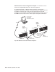
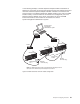
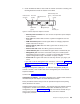
Table Of Contents
- Contents
- Safety
- Chapter 1. Introducing the IBM xSeries 445 server
- Chapter 2. Configuring the server
- Using the Configuration/Setup Utility program
- Using the ServerGuide Setup and Installation CD
- Configuring the Gigabit Ethernet controller
- Using the Integrated System Management Firmware Update Utility program
- Using the LSI Logic Configuration Utility program
- Using ServeRAID Manager
- Remote Supervisor Adapters
- Using the PXE boot agent utility program
- Appendix A. Getting help and technical assistance
- Appendix B. Notices
- Edition notice
- Trademarks
- Important notes
- Product recycling and disposal
- Battery return program
- Electronic emission notices
- Federal Communications Commission (FCC) statement
- Industry Canada Class A emission compliance statement
- Australia and New Zealand Class A statement
- United Kingdom telecommunications safety requirement
- European Union EMC Directive conformance statement
- Taiwanese Class A warning statement
- Chinese Class A warning statement
- Japanese Voluntary Control Council for Interference (VCCI) statement
- Power cords
- Index
2.
Check
the
Ethernet
LEDs
to
ensure
that
the
network
connection
is
working.
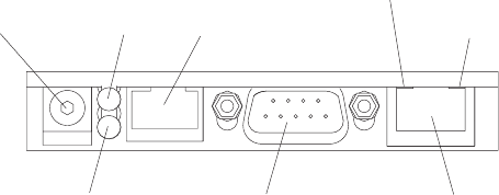
The
following
illustration
shows
the
location
of
the
LEDs.
v
External
power
connector:
You
can
connect
an
optional
ac
power
adapter
to
this
connector.
v
Error
LED:
This
amber
LED
is
lit
when
a
system
management
error
has
occurred.
v
ASM
interconnect
port:
Connect
signal
cables
for
managing
expansion
module
resources
to
this
port.
v
Ethernet
activity
LED:
When
the
LED
is
green
there
is
activity
on
the
Ethernet
LAN.
v
Ethernet
link
LED:
When
the
LED
is
green
the
link
is
active.
v
10/100
Ethernet
port:
Connect
Ethernet
signal
cables
to
the
Ethernet
port.
v
Management
port:
Connect
a
serial
cable
to
this
port
to
enable
system
management
through
a
modem,
or
connect
a
null
modem
cable
to
enable
system
management
through
a
workstation
or
laptop
computer.
v
Power
LED:
This
green
LED
comes
on
and
stays
lit
when
you
plug
in
your
server.
If
you
want
to
use
the
management
port
connection,
continue
with
“Cabling
the
management
(COM)
port”
on
page
55;
otherwise,
go
to
“Configuring
the
adapter.”
Cabling
the
management
(COM)
port:
To
cable
the
management
(COM)
port,
connect
a
modem
or
null
modem
cable
to
the
management
port
on
the
Remote
Supervisor
Adapter.
Continue
with
Configuring
the
adapter.
Configuring
the
adapter:
This
section
describes
how
to
enable
remote
access
to
the
Remote
Supervisor
Adapter
and
install
ASM
device
drivers.
These
procedures
assume
that
you
have
an
operational
keyboard
and
pointing
device
attached
to
the
server.
Enabling
remote
access
to
the
adapter:
The
Remote
Supervisor
Adapter
requires
configuration
to
enable
remote
access
through
either
the
Ethernet
port
or
the
management
port.
From
Table
3
on
page
56,
select
the
interface
method
that
you
want
to
use
to
perform
remote
management;
then,
perform
the
indicated
configuration
procedure.
External power
connector
Error LED
(amber)
Power LED
(green)
ASM interconnect
port
Ethernet link LED
(green)
Ethernet activity LED
(green)
10/100
Ethernet port
Management port
Figure
21.
Remote
Supervisor
Adapter
connectors
Chapter
2.
Configuring
the
server
55