
User's Manual
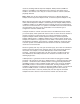
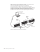
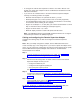
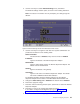
Table Of Contents
- Contents
- Safety
- Chapter 1. Introducing the IBM xSeries 445 server
- Chapter 2. Configuring the server
- Using the Configuration/Setup Utility program
- Using the ServerGuide Setup and Installation CD
- Configuring the Gigabit Ethernet controller
- Using the Integrated System Management Firmware Update Utility program
- Using the LSI Logic Configuration Utility program
- Using ServeRAID Manager
- Remote Supervisor Adapters
- Using the PXE boot agent utility program
- Appendix A. Getting help and technical assistance
- Appendix B. Notices
- Edition notice
- Trademarks
- Important notes
- Product recycling and disposal
- Battery return program
- Electronic emission notices
- Federal Communications Commission (FCC) statement
- Industry Canada Class A emission compliance statement
- Australia and New Zealand Class A statement
- United Kingdom telecommunications safety requirement
- European Union EMC Directive conformance statement
- Taiwanese Class A warning statement
- Chinese Class A warning statement
- Japanese Voluntary Control Council for Interference (VCCI) statement
- Power cords
- Index

In
the
following
example,
a
Remote
Supervisor
Adapter
II-EXA
is
installed
in
an
xSeries
44,
and
creates
an
interconnect
network
with
the
other
xSeries
445
servers
that
have
a
Remote
Supervisor
Adapter
installed.
A
modem
is
connected
to
the
serial
connector
of
the
Remote
Supervisor
Adapter
II-EXA
(on
one
end
of
the
ASM
breakout
cable),
a
second
modem
is
connected
to
the
management
port
of
the
Remote
supervisor
Adapter
in
the
server
connected
to
the
end
of
the
ASM
interconnect
network,
and
a
modem
is
connected
to
the
remote
system-management
administrator’s
system.
Remote system
management
administrator's system
Modem
Modem
Management
port
Modem
Dial-out
only
Note: The ASM Interconnect module is connected to the RS-485 port on the
back panel of the Remote Supervisor Adapter in each server.
xSeries 445
xSeries 445
xSeries 445
ASM
Interconnect
module
RS-485
terminator plug
RS-485
terminator plug
Figure
20.
ASM
interconnect
network
modem
configuration
Chapter
2.
Configuring
the
server
51