HTEB1 User manual Hitachi H8/Tiny 3664F LowCost Evaluation Board User Manual Issue 0.
HTEB1 User manual PREFACE Product Warranty The warranty period against defects in materials and workmanship are as set out in the accompanying Customer Information sheet. Limitation of Warranty The foregoing warranty does not cover damage caused by fair wear and tear, abnormal storage conditions, incorrect use, accidental misuse, neglect, corruption, misapplication, addition or modification or by the use with other hardware or software, as the case may be, with witch the product is incompatible.
HTEB1 User manual Table of Contents PREFACE .............................................................................. 2 Table of Contents .................................................................. 3 1 Overview ......................................................................... 4 1.1 System Development Kit content.................................... 4 1.2 Hardware description .................................................... 4 1.3 Features...............................................
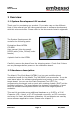
HTEB1 User manual 1 Overview 1.1 System Development Kit content Thank you for purchasing our product. If you take care on the different hints in this manual you will have great success in software development with this microcontroller. Please refer to the documents listed in appendix. The System Development Kit contains the following parts: Evaluation-Board HTEB1 CD-ROM User manual (this document) RS232 cable (1.
HTEB1 User manual 1.3 Features • • • • • • • • • • • • • • • • • Contains H8/3664F microcontroller In-Circuit serial Flash programming All resources available for evaluation All pins routed to connectors 9.8304 MHz main crystal 32.
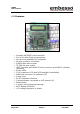
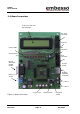
HTEB1 User manual 1.4 Board overview 2*16 char LCD with LED backlight Ext.-LCD connector Contrast 8 user LEDs I2C connector DA connector E10T connector RS232 connector SubD0 female Crystal socket Power 7,5 V9V DC AT/PS2 keyboard connector + - P1 = ADC 0 P2 = ADC 1 Figure 1 Board overview Issue 0.
HTEB1 User manual 1.5 Jumpers and switches JP1 is used for switching the serial interface from 1:1 to crossed connection. If you connect a 1:1 cable (like the cable that comes with the kit) use the default setting. If you connect a crossed cable set the jumper to alternate setting. JP3 is used for the LCD-LED backlight. If the jumper is closed (1-2) the backlight will be ON. Remove the jumper (=open) if backlight operation is not necessary.
HTEB1 User manual S_PROG/RUN switches between RUN- and PROG(PROGRAMMING) mode. KEY_1 (T1) to KEY_4 (T4) are user keys. RESET_KEY (T7) is for reset. Orientation LEFT RIGHT Operation PROG(programming) mode RUN mode Main crystal (Q1) can be changed to another frequency. Therefore a crystal socket is provided. Please refer to the microcontroller hardware documentation for recommended devices. The crystal type should be a HC49 / HC49U type. Eventually change the capacitors C6/C7 if necessary.
HTEB1 User manual 1.6 Connectors X1, Serial communication, SubD-9 female X2, Power connector, for cable connection X4, MiniDIN (PS2) X2, Pin 1 2 Operation GND DC power supply, 7,5 – 9 VDC, approx. 180mA with LED backlight X1 (SubD9), Pin Operation 1 (DTR,DSR, DTS) 2 TXD 3 RXD 4 DTR 5 GND 6 DSR 7 RTS 8 CTS 9 n.c. Remark Connected Connected Connected Connected X4 (Mini-Din) Pin 1 5 3 4 2,6 µC-Pin Operation P17 P16 (can be Data or Clk) (can be Clk or Data) GND Vcc n.c. Issue 0.2 to to to to X1.
HTEB1 User manual OnBoard LCD (IC4) X3, external LCD-connector (057-016-1) X5, E10T debug connector (Sys-Con) LCD Modul X3 (LCD-CON) (IC4) pin (057-016-1) pin 3 1 4 2 5 3 6 4 7 5 8 6 9 7 10 8 11 9 12 10 13 11 14 12 15 13 16 14 1 15 2 16 X5 (SYS-CON), pin 1 5 7 11 13 8 2,4,6,10,12,14 3,9 Issue 0.
HTEB1 User manual SV1,SV2, SV3,SV4 connectors with microcontroller signals SV1 PIN 1,2 3 4 5 6 7 8 9 10 11 12 13 14 15 16 17,18 SV2 Operation PIN GND 1,2 n.c. 3 n.c. 4 P14 5 P15 6 P16 7 P17 8 AN4 9 AN5 10 AN6 11 AN7 12 AN3 13 AN2 14 AN1 15 AN0 16 Vcc 17,18 Issue 0.2 SV3 Operation PIN GND 1,2 n.c. 3 n.c. 4 P22 5 P21 6 P20 7 P87 8 P86 9 P85 10 P84 11 P83 12 P82 13 P81 14 P80 15 /NMI 16 Vcc 17,18 Page 11 SV4 Operation PIN GND 1,2 n.c. 3 n.c.
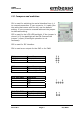
HTEB1 User manual 1.7 Start-Up instructions 1.7.1 Installing the HTEB1 Installing the HTEB1 requires a power supply and a serial connection to a host computer (common PC). The serial communications cable for connecting the HTEB1 to a host computer is supplied and has 1:1 connectivity. PC with COM1/2 Power supply 7,5-9V DC Figure 1.8 shows how to connect the HTEB1 to a PC and to a power supply 1.7.2 Power Supply The HTEB1 hardware requires a power supply of 7,5V DC at minimum.
HTEB1 User manual 1.7.3 Test program The HTEB1 is supplied with a short demo application when delivered. If you power up the eval-board for the first time, you will see a start up message and some LEDs lighting. If no message appear, please set the switch “Prog/Run” to “Run-Mode” (right position) and power up the board or, if already done, press the reset-button. The demo application contains a small “Running-Light” application. The keys can be used for control the state, P2 is used as speed control.
HTEB1 User manual 1.7.4 Software Installation Software development on embesso-HTEB1 requires some software tools to be installed on your PC. All tools can be found on CD-R. Some of them must be installed separately. Please refer on installation / setup requirements.
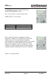
HTEB1 User manual 2 Development Environment 2.1 Creating a program using IAR-EWH8 Software development can be done with a integrated embedded workbench like IAR-EWH8. This software contains an editor, some tools for organization and a tool chain for compiling, assembling and linking programs. Start IAR Embedded Workbench on your PC. The following window will appear: Now select File / New and select “Project” Issue 0.
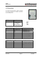
HTEB1 User manual Press OK and a file window will appear. Here first create a new directory (e.g. c:\MyTinyTest) and type the project filename “MyTinyTest”. After that click CREATE. Now a new project is created and we must do some settings. In the window select under targets: “RELEASE”. Issue 0.
HTEB1 User manual Now select release with the right mouse button. A popup appears. Select Options… and do the following settings: In selection ICCH8/List select the List file box. In section XLINK/Output select under Format “motorola” as the output format. Issue 0.
HTEB1 User manual On the CD-R you will find a file called “hteb1.xcl”. That file must be used as the xlink input file. Please copy it to your target directory and select in section Input/XCL file name the file hteb1.xcl. Issue 0.
HTEB1 User manual All other options can be changed later. Click on OK. Now select File/new/source file and type in the following program: /* MyTinyTest */ #include "ioh83664.h" void main(void) { unsigned int x=0; unsigned char c=0; PCR8 = 0xff; PDR8 = c; while (1) { while (--x); c++; PDR8 = c; } } Issue 0.2 /* /* /* /* counter */ holds port output */ port is output */ all LED's on (inverse) */ /* wait ...
HTEB1 User manual After that save it under MyTinyTest.c Now we must add this file to our project. Please select Project/Files and add the file MyTinyTest.c. Issue 0.
HTEB1 User manual After that click on DONE. Now you can select Projet/Build ALL (or F9) and all files are compiled and linked. The message window shows if your project is error free or if there are any errors. Issue 0.
HTEB1 User manual The target file for download can be found in directory c:\mytinytest\release\exe\mytinytest.a37. Please see chapter “FDT” for information about downloading this file to target system. Issue 0.
HTEB1 User manual 2.2 Download the code using FDT After compiling and linking (error free!), the target code (mytinytest.mot) should be downloaded to target board. Therefore we use a freeware tool from HMSE : FDT. Even FDT must be prepared for a new workspace. Issue 0.
HTEB1 User manual Please start FDT and select „New Workspace“. Here we use the project name “MyTinyTest”. You can choose a location for all workspace files. Select on subdirectory from „MyTinyTest“. Click ok and a further window will appear: Select „Yes“ Issue 0.
HTEB1 User manual First time users should use the wizard! Fill in the following things: Issue 0.
HTEB1 User manual Issue 0.
HTEB1 User manual Issue 0.
HTEB1 User manual Now a workspace is created and you can add your target file to „TargetFiles“: Select Project/Add new files to project… and search for file: c:\hew2\mytinytest\mytinytest\release\mytinytest.mot. Issue 0.
HTEB1 User manual Now make a double click on \targetfiles\mytinytest and the file content of mytinytest.mot will appear in hex format in the right window. First press the reset button at the target board, hold it down and move Prog/Run-switch to prog position (left). After that release the reset button. With Image/Download image (Ctrl-P) you one can start the connection setup to target board and start downloading image file. Now press Ctrl-P (Download) on FDT and the download process will start.
HTEB1 User manual Now you can do some additional functions in HEW. After compiling and linking only go to FDT, update your download file with the command Freshen all Target files (Ctrl-T), reconnect the link and repeat the download process. Issue 0.
HTEB1 User manual 2.3 Workflow Issue 0.
HTEB1 User manual 3 Examples HTEB1 is provided with some demonstration code. On the supplied CD-R you should find a complete prepared workspace for IAR-EWH8. \examples\demoapp\demoapp.prj Please copy the complete directory to your hard disk in a directory c:\H8TinyIAR, so you will finally have the following directory (per example) “c:\H8TinyIAR\examples\demoapp\” with all application notes included. Then start IAR-Ewh8 and select “open existing workspace”. Select one of the projects and do your exercises.
HTEB1 User manual 3.1 Key’s and LED’s The first demo program shows the usage of LEDs and keys on HTEB1. For time-controlling we use TIMER_A as an periodic interval timer. The interrupt service routine (isr) is checking the state of the keys, actualising the LED port and reading out the AD1-channel to determine the running light speed. If you want to do some experiments, first check out to find if other LED pattern maybe in form of a table read out or calculate them by functions developed by yourself.
HTEB1 User manual } if (LED_Speed) LED_Speed--; // decrement speed counter if (!LED_Speed) // if zero ...
HTEB1 User manual RunningLightInit(); Timer_A_Init(); while(1); // Init key's and LEDs // init & start timer_A // just wait ... } Issue 0.
HTEB1 User manual 3.2 LCD One of the highlights of the HTEB1 is the 2*16 character LCD with backlight. Simple functions are provided here to demonstrate the usage of the LCD. Please refer to the LCD manual for further information (e.g. commands, other character sets etc.). The demo source contains some definitions to reset and initialise the display. Then we make some simple write outs.
HTEB1 User manual u8 LCDReadStatus(void) { u8 status; CLEAR_LCD_RS; SET_LCD_RW; LCD_DATA_CTRL = LCD_IN; SET_LCD_EN; status = LCD_DATA_PORT; CLEAR_LCD_EN; LCD_DATA_CTRL = LCD_OUT; return status; } void LCDInit(void) { u16 cnt=0; CLEAR_LCD_RS; CLEAR_LCD_RW; CLEAR_LCD_EN; PCR7 |= 0x30; PCR2 |= 0x01; LCD_DATA_CTRL = LCD_OUT; // get the LCD status register // init LCD // Set RS+RW = Output // Set EN = Output // Set DDR to Output LCDWriteCmd(0x38); // 8Bit-IF, 2 Lines, 5x7 character font while(--cnt); LCDWri
HTEB1 User manual void LCDLoopMsg(void) { while(1) // do forever... { LCDWriteLine(0,&Text1[0]); // display msgs LCDWriteLine(1,&Text2[0]); Delay(); LCDWriteLine(0,&Text3[0]); LCDWriteLine(1,&Text4[0]); Delay(); LCDWriteLine(0,&Text4[0]); LCDWriteLine(1,&Text5[0]); Delay(); } } void main(void) { LCDInit(); LCDLoopMsg(); } Issue 0.
HTEB1 User manual 3.3 SCI SCI is used here for a simple RS232 (V24) terminal connection. Please use a terminal program like HyperTerm (included in Windows), select Baudrate 9600 Baud, 8 Databits, No Parity and 1 Stopbit (8N1). After connection and setup, hit some keys and you will see a message responding on every keycode sent. /* **----------------------------------------------------------------------** ** main.
HTEB1 User manual return TRUE; } return FALSE; } u8 V24PutChar(u8 c) { if (IS_SCI_TX_FREE) { TDR = c; return TRUE; } return FALSE; } // simple PutChar via V24 // Tx register free ? // yes, put data in tx register u8 V24Write(u8 *s) // simple Write(string) via V24 { while (*s != 0) // while not end of string { if (V24PutChar(*s) == TRUE) s++; // PutChar } return TRUE; } u8 V24WriteLn(u8 *s) { u8 ret = FALSE; ret = V24Write(s); ret |= V24Write("\n\r"); return ret; } // simple WriteLine (string + CR/LF)
HTEB1 User manual 3.4 A/D + PWM This sample shows the usage of the A/D converter. We sample the voltage of P1/P2, filter it and show the result on the LCD. On D/A-Con you will see a reversed voltage at P2 – built with a RC-filter from TOW (P76).
HTEB1 User manual LCD_DATA_CTRL = LCD_IN; SET_LCD_EN; status = LCD_DATA_PORT; CLEAR_LCD_EN; LCD_DATA_CTRL = LCD_OUT; return status; } void LCDInit(void) { u16 cnt=0; CLEAR_LCD_RS; CLEAR_LCD_RW; CLEAR_LCD_EN; PCR7 |= 0x30; PCR2 |= 0x01; LCD_DATA_CTRL = LCD_OUT; // inits the LCD // Set RS+RW = Output // Set EN = Output // Set DDR to Output // required 3 times pls. ref.
HTEB1 User manual { u8 *data, *text, c,d; if (line==0) text = &Line0[0]; // last digit = start address else text = &Line1[0]; data = text+14; d=3; while (d) { *data = '0'; // default = '0' c = code & 0x000f; // check digit if (c) // if > 0 chk for value { if (c < 10) *data = '0'+c; // 0..9 else *data = 'A'+c-10; // a..
HTEB1 User manual 3.5 AT-Keyboard-Interface This demo shows the usage of the PS2 (mini-DIN) interface on HTEB1. Please connect an AT-keyboard (MF102) to this port. You will see the keycodes, provided by the keyboard on the LCD. Please refer to the code table for keycode translation in your own projects.
HTEB1 User manual SET_LCD_RW; LCD_DATA_CTRL = LCD_IN; SET_LCD_EN; status = LCD_DATA_PORT; CLEAR_LCD_EN; LCD_DATA_CTRL = LCD_OUT; return status; } void LCDInit(void) { u16 cnt=0; CLEAR_LCD_RS; CLEAR_LCD_RW; CLEAR_LCD_EN; PCR7 |= 0x30; PCR2 |= 0x01; LCD_DATA_CTRL = LCD_OUT; // inits the LCD // Set RS+RW = Output // Set EN = Output // Set DDR to Output // required 3 times pls. ref.
HTEB1 User manual if (data & mask) pcnt++; mask >>= 1; } if ((pcnt & 0x01) ^ (data & 0x0100)) return TRUE; return FALSE; } interrupt [IRQ_2] void IRQ_2_Isr(void) { static u8 cnt; static u16 val; // irq on key_clk if (outact) /* do some output? */ { if (outval & 0x0001) PDR1 |= cKEYDATA; else PDR1 &= ~cKEYDATA; outval >>= 1; if (!outval) { PDR1 |= cKEYDATA; // set out=HIGH (1) PCR1 &= ~cKEYDATA; // set portpin as input (0) outact=0; } } else // process input data { val >>= 1; if (PDR1 & cKEYDATA) val |=
HTEB1 User manual keyReadIndex++; if (keyReadIndex >= cKeyBufSize) keyReadIndex = 0; return KeyCode; } u8 buffer[17] = " KeyCode : 0000 \0"; // msg buffer // convert int to ASCII-HEX void ShowCode(u16 code) { u8 *data, c; data = &buffer[14]; // last digit = start address while (code) { *data = '0'; // default = '0' c = code & 0x000f; // check digit if (c) // if > 0 chk for value { if (c < 10) *data = '0'+c; // 0..9 else *data = 'A'+c-10; // a..
HTEB1 User manual Tables : Scan-Codes MFII-Keyboard Numeric Keypad Issue 0.
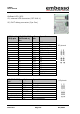
HTEB1 User manual MainKeypad Scan-Code Set 1 Key Make-Code ^ 1 2 3 4 5 6 7 8 9 0 = <-(Backspace) ->| (Tab) q w e r t y u i o p [ ] Return CAPS-Lock a s d f g h j k l ; ' \ left Shift < z x c v b n m , . / right Shift Ctrl Left Win Alt Space AltGr Right Win Menu 29 02 03 04 05 06 07 08 09 0A 0B 0C 0D 0E 0F 10 11 12 13 14 15 16 17 18 19 1A 1B 1C 3A 1E 1F 20 21 22 23 24 25 26 27 28 2B 2A 56 2C 2D 2E 2F 30 31 32 33 34 35 36 1D 5B 38 39 Strg+Alt 5C 5D Issue 0.
HTEB1 User manual Functionand other keys Key Esc F1 F2 F3 F4 F5 F6 F7 F8 F9 F10 F11 F12 Print Scroll Pause Ins Del Pos1 End PgUp PgDn Arrow left Arrow up Arrow down Arrow right Issue 0.
HTEB1 User manual Appendix A: CD-R content Programs IAR-EWH8 \programs\iar\ FDT (flash development toolkit) \programs\fdt\ Examples \examples\demoapp\ Demo \examples\flashdemo\ Datasheets Tiny Hitachi H8/3664F hardware manual, H8 programming manual, Tiny Application notes, LCD-Module, \datasheets\ Documentation This manual as pdf \documentation\ HTEB1 board schematic \documentation\schematic\ Issue 0.
HTEB1 User manual Appendix B: Schematic Issue 0.
HTEB1 User manual Appendix C: Board layout Issue 0.
HTEB1 User manual NOTES Issue 0.
HTEB1 User manual NOTES Issue 0.
HTEB1 User manual Issue 0.