User’s Manual Fire Alarm Back-up UPS1481 UNIT Emergency Power Systems Doc #.
OnLine Power FIRE ALARM BACK-UP UPS1481 UNIT, Congratulations on selecting one of the fine products from On-Line Power, the Leader in Power Protection Technology. Our wide product offering includes Uninterruptible Power Systems (UPS), Power Conditioners, Automatic Voltage Regulators and Specialty Transformers (e.g. computer-grade, medicalgrade).
OnLine Power On-Line Power, Inc. Proprietary Reproduction or Distribution forbidden NOTICE: THIS DOCUMENT CONTAINS PROPRIETARY INFORMATION This document contains proprietary and confidential information of On-Line Power, Inc. (”On-Line Power”).
OnLine Power DANGER!! THIS DANGER SYMBOL IDENTIFIES A CONDITION OR ACTION WHICH WILL RESULT IN SEVERE INJURY OR DEATH TO AN INDIVIDUAL OR SEVERE DAMAGE TO EQUIPMENT OR OTHER PROPERTY. CAUTION This Caution symbol identifies a condition or action which may result in minor injury to an individual or minor damage to the equipment or other property. This unit was designed for specific applications. It should not be modified and/or used for any application other than for that which it was designed.
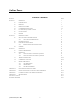
OnLine Power TABLE OF CONTENTS SECTION PAGE SECTION 1 OPERATION 1 1-1 INTRODUCTION 1 1-2 BENEFITS 2 1-3 PRODUCT FEATURES 1, 5 1-4 CUSTOMERS CONNECTIONS 6-9 1-5 Fire Alarm Back-up UPS1481 SIZING 9 1-6 OUTPUT LOADS 9 1-7 SECTION 2 2-1 OPTIONS 9 PREINSTALLATION 11 SITE P LANNING AND PREPARATION 12 2-1-1 13 LOCATION CONSIDERATIONS 2-2 PRE-INSTALLATION 14 2-3 ELECTRICAL CONNECTIONS 14 2-3-1 15 2-4 SECTION 3 REMOTE SIGNALING CONNECTIONS STORAGE 16 OPERATION 18 3-1
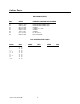
OnLine Power REVISION HISTORY REV DATE PRIMARY REASON FOR CHANGE X1 X2 X3 X4 X5 X6 X7 X8 APRIL 4, 2004 FEB 22, 2005 OCT 30, 2006 NOV 03, 2006 MAY 21, 2007 JUN 21, 2007 Nov. 15, 2007 MAY 30, 2008 RELEASE FOR PRODUCTION RELEASE FOR PRODUCTION UPDATE UPDATE P11, P29. UPDATE UPDATE Per UL Review PER UL REVIEW LIST OF EFFECTIVE PAGES PAGE REV a ii 1 5-9 12 – 13 18 – 19 22 26 – 27 29 31-40 X7 X7 X7 X7 X7 X7 X7 X7 X7 X7 PAGE REV X8 X8 X8 X8 X8 X8 X8 X8 X8 X8 (6002-1646) REV.
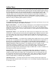
OnLine Power SECTION 1 OPERATION — 1-1 INTRODUCTION The Fire Alarm Back-up UPS1481 provides an exceptional level of load protection and monitoring capabilities. The critical load is provided with conditioned, regulated, computer grade power at all times. There is complete electrical isolation between the input and output voltage of the UPS. When input power to the UPS is lost, such as during a power outage, the UPS automatically draws power from its internal battery supply.
OnLine Power systems, from electrical interference. The Fire Alarm Back-up UPS1481 protects these systems from power problems associated with poor quality AC power including complete power Outages. Electrical disturbances can come from practically anywhere: from the incoming power lines and even from within a building. Outside electrical disturbances include lightning strikes, utility switching, brown—outs, and accidents.
OnLine Power Optional Output Isolation Transformer — This transformer is provided when the input and output voltages are different, or multiple output voltages are required or an isolation at output is required. The power to the primary of this transformer is selected either from UPS via output static switch and from utility input via bypass static switch. The two static switches toggle on/off as controlled by control board. Battery Charger — The battery charger maintains the batteries at full charge.
OnLine Power (6002-1646) REV.
OnLine Power 1-3 FUNCTIONAL BLOCK DIAGRAM (CONTINUED) THE FUNTIONAL BLOCK DIAGRAM OF U.P.S INPUT CONTACTOR INPUT C.B. TB1 1 INPUT FILTER 2 L1 C1 L2 T2 FAX XFMR FILTER (OPTION) 3 K1 FANS SCR DRIVER K INPUT POWER T.B. 7 T2 STEP DOW N tvss T4 CONTACTOR COIL FULL BRIDGE RECTIFIER BR1 (+) DC CHOPPER UP/DOWN BATT. CHARGER (-) Q3/4 Q5/6 POWER FACTOR CONTLR INVERTER L2 Q1 / Q2 PRIMARY BATT BATT C.B.
OnLine Power 1-4 CUSTOMERS CONNECTIONS 1-4-1 Input Power Connection by Customer (with no input C/B option) Connect input (Hot) at TB-1 Connect input Hot / Neutral at TB1-2 Connect input ground at TB1-3 (From External Battery Cabinet) (TO CUSTOMER’S LOAD) OUTPUT (TB2) INPUT (TB 1) 1 2 3 1 2 3 HOT HOT ( N) GND OV 120V OV 4 5 BATTERY CONNECTION (TB3) 6 120V 7 1 2 3 GND (+) (-) GND PROTECTOR CUSTOMER ’S CONNECTION TERMINAL BLOCK ILLUSTRATION 1 - 5 Input wirings for various input v
OnLine Power 1-4-2 OUTPUT POWER CONNECTION BY CUSTOMER FOR SAME INPUT AND OUTPUT VOLTAGE UNIT @ WITHOUT OUTPUT XFMR. 1. 120V IN/OUTPUT UNIT TB2 7 6 N/C 5 OUTPUT CB PB2/1 B 4 N/C 3 A 2 C H 1 N GND (OPTION) UPS CABINET 2. TO CUSTOMER LOAD 120V OUT 240V IN/OUTPUT UNIT 7 6 TO CUSTOMER LOAD 5 PB2/1 B OUTPUT CB 4 H1 120V 3 A 2 C 1 N 240V 120V H2 (OPTION) UPS CABINET (6002-1646) REV.
OnLine Power 1-4-3 OUTPUT POWER CONNECTION BY CUSTOMER FOR DIFFERENT INPUT / OUTPUT VOLTAGES USING OUTPUT XFMR. 1. 240V/120 OUTPUT UNIT TB2 OUTPUT CB PB2/1 A B 1 157V 7 8 6 120V 9 5 88V 11 4 0V 12 3 13 2 14 1 TO CUSTOMER LOAD H1 240V 2 4 120V 5 120V 6 7 C 0V 120V 240V N 120V H2 (OPTION) FOR EACH OUTPUT VOLT CONNECT TO TB2-1 FOR 120 VOLT UNITS, BUT 240/120V UNIT CONNECT TO TB2-3 2.
OnLine Power 3. WITH EXTRA AUX. OUTPUT CIRCUIT BREAKERS FOR VARIOUS OUTPUT VOLTAGES. TB2 7 6 GND 5 4 N E U T R A L 3 2 OUTPUT CB a). ALL AUX OUTPUT CIRCUIT BREAKERS ARE CONNECTED AT UPS SIDE (HOT SIDE) AND CUSTOMER LOAD SHALL BE CONNECTED TO THE INDIVIDUAL AUX CBX NEUTRAL WIRES TO NEUTRAL TB AND GROUND WIRES TO GROUND TB b). OUTPUT RECEPTACLES ARE CONNECTED TO TB2-OUTPUT TB AT UPS SIDE (HOT SIDE) AND CUSTOMER LOAD SHALL BE CONNECTED TO THE INDIVIDUAL AUX. RECEPTACLES.
OnLine Power The total load to be powered by the Fire Alarm Back-up UPS1481 must not exceed its rating. If the total load is exceeded, the Fire Alarm Back-up UPS1481 monitoring will sense an overload condition and a summary alarm will occur. The overload condition must be corrected by increasing the kVA rating of the Fire Alarm Back-up UPS1481. 1-6 OUTPUT LOADS The Fire Alarm Back-up UPS1481 is designed to power any critical, computer, florescent, or incandescent lighting.
OnLine Power SECTION 2 INSTALLATION - 2-1 SITE PLANNING AND PREPARATION The Fire Alarm Back-up UPS1481 is designed for installation indoors and meets NEMA specifications for operating temperature, humidity, and utility voltage. These cabinets are corrosion resistant and rugged. The footprint of the Fire Alarm Back-up UPS1481 is less than 6 square feet. Listed below are the environmental specifications for the Fire Alarm Back-up UPS1481.
OnLine Power TABLE 2-1 SITE PLANNING SPECIFICATIONS FOR KVA UNIT MODEL NUMBER IkW / kVA INPUT VOLTAGE INPUT AMP OUTPUT VOLTAGE OUTPUT AMP DC VOLT DC AMP QTY. BATT PER SET 96V 43A 8 96V 43A 8 1 2 WR3.0A58FPT1 3.0 120 40 120/240 WR3.0B58FPT1 3.0 208 19 120/240 3 WR3.0D58FPT1 3.0 240 19 120/240 12.50 @240 96V 43A 8 5 WR5.0A58FPT1 5.0 120 58 120/240 41.70 @120 120V 57A 10 6 WR5.0B58FPT1 5.0 208 30 120/240 120V 57A 10 7 WR5.0D58FPT1 5.
OnLine Power UL1481 MICRO-CHIPS & OTHER COMPONENT’S LIST INPUT OUTPUT KW / VOLTAGE KVA MODEL NUMBER MICRO-CHIP SOFTWARE BASIC UPS KIT LABEL KIT INPUT CONTACTOR BATT C.B. FANS 9100-1312-11 9100-1295-02 1680-242 2025-769 1000-036 1 2 WR3.0A58FPT1 120 120/240V 9100-1319-018UL WR3.0B58FPT1 208 120/240V 9100-1319-023UL 3 WR3.0D58FPT1 240 120/240V 9100-1319-025UL 9100-1312-11 ‘’ " " ‘’ 5 WR5.0A58FPT1 120 120/240 9100-1319-050UL 9100-1312-11 ‘’ 1680-093 2025-768 ‘’ 6 WR5.
OnLine Power 2-2 Pre-Installation The Fire Alarm Back-up UPS1481 is designed for indoor installations. All customer connections are brought through knockouts located on the top or side of the Fire Alarm Back-up UPS1481. The Fire Alarm Back-up UPS1481 consists of one (1) integrated cabinet — housing both the electronics and batteries (depending on KVA). Before unpacking the equipment, inspect the exterior the shipping container and the equipment itself for damage that may have occurred during transit.
OnLine Power 1. Verify that the main input circuit breaker, battery circuit breaker, and output circuit breaker(s), if provided are in the “OFF” position. See illustration 1-2 for the locations of the circuit breakers. See under Section 2-5, Storage for accessing the inside of the unit. 2. Run the power wires up through the center area of the Fire Alarm Back-up UPS1481. Exercise care when working around the battery area. 3. Refer to Section 1-4 for various different installation configurations. 4.
OnLine Power 3. Determine which signals will be used. Connect wires (customer-supplied) to the connector. 4. This concludes the remote signaling connection procedures. 5. This concludes the installation procedures. Please proceed to Section 3-Start-Up for these necessary to start- up the Fire Alarm Back-up UPS1481. AS400 CONNECTION DETAILS (J2) K1 K2 K3 K4 9 INPUT FAIL 8 LOW BATT.
OnLine Power During long-term storage, the batteries are subject to aging and deterioration. If after visual inspection, the batteries need to be replaced contact your OnLine Power dealer or the OnLine Power factory directly to obtain new batteries. The UPS is stored in its original packaging, unpack UPS using unpacking procedures outlined in Section 2-3-1.
OnLine Power SECTION 3 OPERATION - 3-1 Start-Up Procedures 1. Verify that the main input circuit breaker, battery breaker, and output circuit breaker(s), if provided, are in the “OFF” or “down” positions. Refer to illustration 1-2 for the locations of the circuit breakers. CAUTION CAUTION It during the start- up procedures anything unusual occurs, immediately turn off the Input circuit breaker, and contact OnLine Power at (800) 797-7782 for technical assistance.
OnLine Power 6. At this point in time, the Fire Alarm Back-up UPS1481 should be providing AC line power. The Fire Alarm Back-up UPS1481 is not operating in the normal mode, turn off the input circuit breaker. Contact OnLine Power at (800) 797-7782 for technical assistance. 7. Recheck that the output voltage is 120/240 VAC. • If the output voltage is approximately same as nameplate, turn on the loads which will be powered from the Fire Alarm Back-up UPS1481 . 8.
OnLine Power 3-2-2 Turning off the Fire Alarm Back-up UPS1481 : 1. Turn off the Output Breaker(s), if provided. 2. Turn off the Battery Breaker. 3. Turn off the Input Breaker, if provided. 3-3 Theory of Operation Illustration NO TAG is a simplified block diagram of the Fire Alarm Back-up UPS1481. This diagram provides an excellent tool in identifying the major building blocks within the Fire Alarm Back-up UPS1481 . 1. 2.
OnLine Power 9. Optional Output Isolation Transformer (TI) — The transformer performs a number of critical functions. First, it provides excellent common mode and normal mode noise isolation of the load from the input or inverter power. Secondly, it provides voltage transformation and tight regulation of the output voltage while the Fire Alarm Back-up UPS1481 is operating from its internal inverter or directly from utility via bypass circuitry. 10.
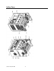
OnLine Power 3-4 COMPONENT’S LOCATION & LIST (6002-1646) REV.
OnLine Power COMPONENT’S TABLE (6002-1646) REV.
OnLine Power (6002-1646) REV.
OnLine Power 3-4 ITEM 18 (CONTINUED) (6002-1646) REV.
OnLine Power APPENDIX A: EXTENDED BATTERY RUN CHART Battery kitPart# LoadKV A Minutes 7050354 0.5 7050355 0.75 7050356 1.0 7050358 2.0 7050359 3.0 7050360 4.0 7050361 5.0 70503627.5 705036310.0 705036412.5 -015 -015 -015 -015 -015 015 -015 -015 -015 -015 -015 Batt.
OnLine Power OTHERS ARE CALCULATED VALUES BASED ON THE BATTERY MANUFACTURER'S DATA FOR BACK UP TIME. APPENDIX B – Optional Main Input & Main Output Breakers for various models (*All Values are typical as reference only) TABLE B-1: External Output Breaker (Standard KAIC) KVA 3 5 7.5 10 12.
OnLine Power INPUT CIRCUIT BREAKER TABLE B-3: Input Breaker Ampacity (Standard KAIC) KVA 3 5 120 Vac 50 Amps, 120 VAC, 1 Pole, 14 KAIC OLP P/N: 2025-784 70 Amps, 120 VAC, 1 Pole, 14 KAIC OLP P/N: 2025-997 7.5 N/A 10 N/A 12.
OnLine Power APPENDIX C: LCD DISPLAY MENU & TROUBLSHOOTING GUIDE Two screens (A, B) are updated continuously for units without optional output transformer. Three screens (A, B, C) are updated continuously for units with optional output transformer. Start-up Screen When input power is applied for the unit, LCD panel lights up and displays OnLine Power UPS Project If LCD display panel is not lit, unit has a problem. Contact factory service at 1–800–PWRSRVC at OnLine Power.
OnLine Power SCREEN B: The screen appears as below. Line 1 Line 2 Line 3 Line 4 OUTPUT: ______V INPUT : ______V DC BUSS: ______V BATT: ________V @ @ @ @ ______ ______ NA +______ W A A A 4. Indicates output voltage and power in watts, when output transformer is not used. It indicates primary voltage of the output transformer (T1) (120 VAC, typically) when T1 is used. 5. Indicates input volts and Amps. 6. Indicates internal DC buss condition for factory use. 7. Indicates battery voltage.
OnLine Power (6002-1646) REV.
OnLine Power APPENDIX D: SPECIFICATION POWER RATING (KW) VOLTAGE 5.0 3.0 (VAC) INPUT MAXIMUM CURRENT 7.5 Single Phase, 120/208/240 40/19/16 12.5 15 Single Phase, 240/208VAC 58/30/28 41/36 58/50 69/60 83/72 +10% to -15% TOLERANCE FREQUENCY 10 60 +/- 3% (Hz) 0.98 to 1.0 (Typical) POWER FACTOR Electronic / Circuit Breaker OVERCURRENT PROTECTION 2 Wires plus Ground NUMBER OF WIRES Hard Wired (Terminal Block) POWER CONNECTION OUTPUT RATING (KVA/KW) VOLTAGE 5.0 3.
OnLine Power POWER RATING (KVA/KW) 5.0 3.0 10 7.5 12.5 15 BATTERY BATTERY RUN TIME See Appendix C for various Run time BATTERY TYPE NOMINAL DC VOLTAGE Sealed, Maintenance-Free, AGM, VRLA type 96 VDC 120 VDC OVERCURRENT PROTECTION 120 VDC 192 VDC 192 VDC 240 VDC Circuit Breaker PACKAGING Batteries Housed in Same Enclosure and/or additional battery cabinet (See Table 2-1) MONITORING AND COMMUNICATIONS LCD SCREEN Input Voltage, Batt. Charger, UPS Output; On Batt.; Low Batt.
OnLine Power (6002-1646) REV.
OnLine Power (6002-1646) REV.
OnLine Power BATTERY CABINET "B" 2ND LEVEL + + + + BATT C.B + TB3 BATT C.B 1 1ST LEVEL #6 #7 #8 9 + + + + #10 120VDC BUSS + 2 3 #5 #3 #4 #2 #1 UPS CAB B" CABINET BATTERY )QTY:10) SYSTEM 4TH LEVEL + #16 + + + + + #15 #14 #13 #12 #11 + + + + + 3RD LEVEL 2ND LEVEL BATT C.B TB3 BATT C.B 1 #6 #7 #8 9 + + + + #10 192VDC 1ST LEVEL + 2 #5 #4 #3 #2 #1 3 UPS CAB "B" OR "C" BATTERY (QTY 16) SYSTEM CABINET (6002-1646) REV.
OnLine Power 4TH LEVEL + + + + + #17 #18 #19 #20 + + + + + #15 #14 #13 #12 #11 + + + + + #16 3RD LEVEL 2ND LEVEL 1ST LEVEL BATT C.B TB3 + 1 #10 - 2 + 3 3 BATT C.B VDC BUSS #6 #7 #8 9 + + + + #4 #3 UPS CAB #5 #2 #1 "C" CABINET BATTERY (QTY:20) SYSTEM UPS CONTROL CABINET "A" TB3 2ND LEVEL 1ST LEVEL + + + + 1 BATT C.B + 192VDC BUSS #8 #7 #6 #5 + + + + #4 #3 #2 #1 96VDC 3KW/5KW (8X35AH) BATERRY SYSTEM ONLY (6002-1646) REV.
OnLine Power BATTERY CABINET "B" 2ND LEVEL + + + + BATT C.B TB3 BATT C.B 1 1ST LEVEL #8 #7 #6 #5 + + + + 96VDC 2 3 #3 #4 #2 #1 UPS CAB B CABINET BATTERY (QTY: 8 ) SYSTEM (6002-1646) REV.
OnLine Power (6002-1646) REV.
OnLine Power (6002-1646) REV.
OnLine Power (6002-1646) REV.
OnLine Power (6002-1646) REV.
OnLine Power (6002-1646) REV.
OnLine Power (6002-1646) REV.