User’s Manual Thank you very much for purchasing the product. • To ensure correct and safe usage with a full understanding of this product's performance, please be sure to read through this manual completely and store it in a safe location. • Unauthorized copying or transferral, in whole or in part, of this manual is prohibited. • The contents of this operation manual and the specifications of this product are subject to change without notice.
For the USA FEDERAL COMMUNICATIONS COMMISSION RADIO FREQUENCY INTERFERENCE STATEMENT This equipment has been tested and found to comply with the limits for a Class A digital device, pursuant to Part 15 of the FCC Rules. These limits are designed to provide reasonable protection against harmful interference when the equipment is operated in a commercial environment.
GENERAL SAFETY RULES WARNING ! Read and understand all instructions. Failure to follow all instructions listed below, may result in electric shock, fire and/or serious personal injury. SAVE THESE INSTRUCTIONS. Work Area Tool Use and Care Keep your work area clean and well lit. Cluttered benches and dark areas invite accidents. Use clamps or other practical way to secure and support the workpiece to a stable platform.
RÉGLES DE SÉCURITÉ GÉNÉRALES AVERTISSEMENT ! Vous devez lire et comprendre toutes les instructions. Le non-respect, même partiel, des instructions ci-après entraîne un risque de choc électrique, d'incendie et/ou de blessures graves. CONSERVEZ CES INSTRUCTIONS Aire de travail Veillez à ce que l'aire de travail soit propre et bien éclairée. Le désordre et le manque de lumière favorisent les accidents.
Table of Contents About the Documentation for This Machine .................................................................................................. 4 Documentation Included with the Machine .................................................................................................................. 4 Viewing Manuals in Electronic Format ........................................................................................................................ 5 To Ensure Safe Use ...............
Table of Contents 4. Performing Cutting Using a Computer ......................................................... 57 4-1. Procedures for Performing Cutting Using a Computer ........................................................................ 58 4-2. Setting the Cutting Parameters ............................................................................................................ 59 Types of Cutting Parameters .....................................................................................
Table of Contents 6-4. Detailed Description of the Menus ..................................................................................................... 108 Main Menu ................................................................................................................................................................ 108 [I/O] Submenu ...........................................................................................................................................................
About the Documentation for This Machine Documentation Included with the Machine User's Manual (this manual) This describes important notes for ensuring safe use, and explains how to install the machine and how to install and set up the included programs. Be sure to read it first. It does not describe how to operate your computer or how to use the programs. Dr. Engrave User's Manual (electronic-format manual) This manual explains how to use the included engraving program.
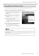
About the Documentation for This Machine Viewing Manuals in Electronic Format You can view the manuals in electronic format on a computer running Windows (Windows 95 or later). Procedures for Viewing Manuals in Electronic Format 1 Place the Roland Software Package in the CDROM drive. The menu screen appears automatically. 2 Click the [Click here] message, then choose the name of the model you're using (EGX-600 or EGX-400). 3 Click the [?] button.
To Ensure Safe Use About and Notices Used for instructions intended to alert the user to the risk of death or severe injury should the unit be used improperly. Used for instructions intended to alert the user to the risk of injury or material damage should the unit be used improperly. * Material damage refers to damage or other adverse effects caused with respect to the home and all its furnishings, as well to domestic animals or pets.
To Ensure Safe Use Do not use with a damaged power cord or plug, or with a loose electrical outlet. Doing so may lead to fire, electrical shock, or electrocution. Do not damage or modify the electrical power cord, subject it to excessive bending, twisting, pulling, binding, or pinching, or place any object or weight on it. Doing so may damage the electrical power cord, leading to fire, electrical shock, or electrocution.
To Ensure Safe Use Use a commercially available brush to remove metal cuttings. Attempting to use a vacuum cleaner to take up metal cuttings may cause fire in the vacuum cleaner. Unpacking, installation, and moving are operations that must be carried out by four or more persons. Failure to do so may result in falling of the unit, leading to injury. Do not carelessly insert the hands while in operation. Fasten the spindle, tool, and material securely in place. Doing so may result in injury.
To Ensure Safe Use About the Labels Affixed to the Unit These labels are affixed to the body of this product. The following figure describes the location and content of these messages. Caution: high temperatures. Do not touch immediately after a cutting operation has ended. Use care to avoid being pinched. Keep hands away during operation. Use caution when handling or working with the blade. Careless handling may result in injury. Model name Rating plate Use a rated power supply.
Pour utiliser en toute sécurité Avis sur les avertissements Utilisé pour avertir l'utilisateur d'un risque de décès ou de blessure grave en cas de mauvaise utilisation de l'appareil. Utilisé pour avertir l'utilisateur d'un risque de blessure ou de dommage matériel en cas de mauvaise utilisation de l'appareil. * Par dommage matériel, il est entendu dommage ou tout autre effet indésirable sur la maison, tous les meubles et même les animaux domestiques.
Pour utiliser en toute sécurité Ne pas utiliser si le fil ou la fiche électriques sont endommagés; ne pas brancher dans une prise mal fixée. Négliger de suivre cette consigne risque de provoquer un incendie ou decauser une décharge électrique ou une électrocution. Si l'appareil reste inutilisé pendant de longues périodes, débrancher la fiche de la prise.
Pour utiliser en toute sécurité Utiliser une brosse du commerce pour retirer les rognures de métal. Tenter de retirer les rognures de métal à l’aide d’un aspirateur peut faire naître un incendie dans l’aspirateur. Lorsque vous déplacez l'appareil, le saisir par sa base en aluminium et le transporter à 4 personnes ou plus. Si l'appareil est saisi par la plaque du dessus, il peut tomber et entraîner des blessures. Faire attention de ne pas insérer ses mains pendant le fonctionnement.
Pour utiliser en toute sécurité À propos des étiquettes collées sur l'appareil Ces étiquettes sont collées à l'extérieur de l'appareil. Les dessins suivants indiquent l'endroit et le contenu des messages. Attention : températures élevées. Ne touchez pas immédiatement après avoir effectué une coupe. Soyez prudent et évitez les pincements. Éloignez les mains pendant le fonctionnement. Soyez prudent lorsque vous manipulez ou utilisez la lame, sinon vous risquez de vous blesser.
14
1. Getting Started This chapter describes the procedures extending from unpacking the machine to installing it, and also explains such matters as required terminology and other background knowledge.
1-1. Included Items and Accessories Follow the steps in "Unpacking and Repacking" on the packing carton to take out the included items and accessories. Before you attempt installation, make sure all the included items are present.
1-2.
1-2. Names and Functions Rear Power-cord connector Power switch Expansion connector 1 This connector is for transmitting the rotation of the spindle to an external device. Expansion connector 2 This is for communication with an external device using the teaching feature. Parallel connector This connector is for connection to the printer port on the computer. Serial connector This connector is for connection to the COM port on the computer.
1-3. Installation and Cable Connections Installation Site and Operating Environment Install on a stable surface. Failure to do so may result in the unit tipping over, leading to injury. Unpacking, installation, and moving are operations that must be carried out by four or more persons. Failure to do so may result in falling of the unit, leading to injury. Use this machine in an environment that meets the following conditions.
1-3. Installation and Cable Connections Connecting the Cables Ground the unit with the ground wire. Failure to do so may result in risk of electrocution in the event of a mechanical problem. Use only with the power cord included with this product. Use with other than the included power cord may lead to fire or electrocution. Do not use with any electrical power supply that does not meet the ratings displayed on the unit. Use with any other power supply may lead to fire or electrocution.
1-3. Installation and Cable Connections Front Do not insert an Ethernet cable or connect to a modular jack. Insert until it clicks into place. Operation-panel connector cable Rear Power connector Parallel Serial connector connector Secure with the clips. Printer port Secure with the screws. Serial port Power outlet Printer cable Power cord Serial cable Connect either a printer cable or serial cable.
22
2. Basic Operation This chapter describes what you should know before you try to use the machine, such as the most basic operations and the procedures for safe use and handling. Be sure to read this chapter before you go on to the next step. Operating the buttons makes the machine move. When operating the buttons, be sure to keep your hands away from the machine. Do not let your hair, necktie, or the like touch the machine. There is danger of becoming it caught on the spindle or other moving parts.
2-1. Emergency Stop to Ensure Safety How to Perform an Emergency Stop To stop the machine in an emergency in order to avoid danger, press the emergency stop switch. The machine immediately stops operating and quits cutting. Cutting cannot be resumed. To Cancel an Emergency Stop To cancel an emergency stop, turn the emergency stop switch in the direction of the arrow. The machine returns to the state it was in immediately after powerup.
2-2. Switching the Power On and Off Switching On the Power Keep your hands away from the machine when you turn on the power. Also, do not place and objects where they may obstruct the operation of the spindle head, X-axis rail, bed, or other components. Turning On the Power 1 Turn on the power switch on the back of the machine. The display shows the model name, and while this is displayed, internal initialization is performed. This takes about ten seconds. EGX-600 Roland DG Corp.
2-3. Moving the Spindle Head Do not put the operation panel on the machine while operation. Doing so may result in unexpected problems. Moving the Spindle Head The spindle head moves in three directions, along the X, Y, and Z axes. When the display shows the top screen, pressing the movement buttons effects movement in the corresponding directions. Make sure the display shows the top screen. You cannot perform movement several times to display the when any other screen is displayed. Press top screen.
2-3. Moving the Spindle Head Moving the Spindle Head Out of the Way Quickly This feature moves the spindle head directly to the back-left position of the table (the VIEW position). This is handy when loading or detaching a workpiece. Moving to the VIEW Position 1 Press pears. until the screen shown at right ap- 2 Press . 3 Press The blinking cursor moves to [VIEW]. HOME Z1 VIEW Z0 Z2 HOME Z1 VIEW Z0 Z2 . The spindle head rises to the highest point, then moves to the VIEW position.
2-4. Starting and Stopping Spindle Rotation Using Buttons to Start and Stop Rotation Holding down for 0.5 seconds or longer makes the spindle rotate. Pressing it again stops rotation. When the spindle cover is open, the spindle does not rotate. Adjusting the Spindle Rotating Speed To adjust the spindle rotating speed, you use the dial on the operation panel. The top screen displays the spindle rotating speed. Spindle rotating speed Slow Avoid turning the dial while cutting is in progress.
2-4. Starting and Stopping Spindle Rotation Forced Stop of Spindle Rotation With this machine, you can set whether or not the spindle rotates. When it is set to rotate, rotation automatically starts when a command is received from the computer and stops when cutting ends. When set not to rotate, no rotation at all takes place. (Rotation does not occur even if you press .) You use this feature at times such as when you are performing scribing using a diamond scraper.
2-5. Menu Operations Displaying the Menus All settings for this machine are made using menus. Pressing the following buttons displays the menu screens. Main menu X/Y-axis origin-point setting menu Pause menu (when pressed during cutting) Z-axis origin-point setting menu Copy menu For detailed information on using the menus ☞ See p.104 "Menu Flowchart" ☞ See p.108 "Detailed Description of the Menus" Basic Menu Operations When you display the menus, the buttons function as follows.
2-6. Care and Handling of Memory Cards This section describes the basic usage and handling of memory cards. This machine can execute cutting data saved on a memory card, and can save sequences created using the teaching feature. For more information about these operations, see "Executing Cutting Data Saved on a Memory Card" on p.65 and "The Teaching Feature" on p.71.
2-6. Care and Handling of Memory Cards Inserting and Removing a Memory Card Inserting a Memory Card 1 Make sure the display shows the top screen. 2 Remove the slot cover. 3 Hold the card with the label side facing up and the notch on the right, and insert it into the memory-card slot. Press it in gently until it clicks into place. 4 Attach the slot cover. X Z 0 0 Y 40700 8000RPM ◆ Be careful to orient the memory card correctly when inserting it.
2-6. Care and Handling of Memory Cards Removing a Memory Card 1 Make sure the display shows the top screen. 2 Remove the slot cover. 3 Gently press the card in until it clicks into place, then pull it out from the memory-card slot. 4 Attach the slot cover. X Z 0 0 Y 40700 8000RPM 1. 2. Do not switch off the power while a memory card is being accessed. Do not switch off the machine while the display shows a message such as [Now Processing].
2-6. Care and Handling of Memory Cards Formatting a Memory Card Formatting a memory card is normally not necessary. However, the machine may be unable to use a memory card that has been reformatted for use with another device, such as a digital camera. In such cases, use the following method to reformat the card again. Formatting deletes all data saved on the memory card. Before you format the card, make sure that it contains no data you want to keep.
3. Preparations This chapter describes how to install a cutter, how to load a workpiece, and other preparations you make before you carry out cutting.
3-1. Selecting the Cutter Installation Method Cutter Types and What They Are Suited For You can install any of a wide variety of tools on this machine. You can also choose whether to use the depth regulator nose unit (nose unit). Choose a tool suited to the task at hand, and decide whether to use the nose unit. Tool With nose unit Character cutter Flat cutter ◆ Engraving acrylic and other plastic plates No nose unit (*1) ☞ p.
3-2. Cutter Installation Method 1 (With Nose Unit) This is for when you perform engraving using the nose unit on an acrylic plate or the like. The tip of the nose traces the material surface, which facilitates obtaining a uniform cutting-in depth. The tool used is a character cutter or a flat cutter. This method is not suitable for aluminum, brass, or other materials that are easily scratched.
3-2. Cutter Installation Method 1 (With Nose Unit) Installing a Character Cutter (With Nose Unit) While installing the cutter, do not allow the operation panel to be touched inadvertently. When using the operation panel, keep hands away from moving areas of the machine. Unintended operation of the machine may lead to danger of becoming caught. Do not touch the tip of the cutter. Doing so may result in injury. Securely fasten the cutter and workpiece in place.
3-2. Cutter Installation Method 1 (With Nose Unit) 2. Nose-unit Installation and Menu Settings 5 Install the nose unit. Tighten fully, then loosen two turns. 6 Fully loosen the lock nut. Be sure to loosen the lock nut. 7 8 9 Use the menus to set [AUTO Z CONTROL] to ON. (1) Press several times to display the screen shown at right. (2) Press to move the blinking cursor to [OTHERS], then press (3) Press several times to display the screen shown at right.
3-2. Cutter Installation Method 1 (With Nose Unit) 3. Cutter Installation and Alignment 10 Lower the spindle until the tip of the nose unit touches the table. When the nose touches the table, operation stops automatically. 11 Insert the cutter (diameter 4.36 mm), then bring the tip lightly into contact with the table. When you insert the cutter, orient it so that it will not catch on the collet.
3-2. Cutter Installation Method 1 (With Nose Unit) 14 Close the spindle cover. 1. 3. 2. Cutting Parameters When Using the Nose Unit When you use the preceding method, there is no need to set the cutting-in depth or the cut-out amount by a software or the operation panel. The cutting-in depth is determined mechanically by the amount of tightening of the nose unit. For more information about how to set the cutting parameters ☞ See p.59 "Setting the Cutting Parameters" ☞ See p.
3-3. Cutter Installation Method 2 (No Nose Unit) This is for when you perform engraving without using the nose unit. The tool used is a character cutter or a flat cutter. This method does not scrape the workpiece, so it is suitable for aluminum, brass and other materials that are easily scratched. Note, however, that in order to obtain a uniform cutting-in depth, the thickness of the workpiece must also be uniform.
3-3. Cutter Installation Method 2 (No Nose Unit) Installing a Character Cutter (With No Nose Unit) While installing the cutter, do not allow the operation panel to be touched inadvertently. When using the operation panel, keep hands away from moving areas of the machine. Unintended operation of the machine may lead to danger of becoming caught. Do not touch the tip of the cutter. Doing so may result in injury. Securely fasten the cutter and workpiece in place.
3-3. Cutter Installation Method 2 (No Nose Unit) 2. Menu Settings 5 Fully tighten the lock nut. 6 Use the menus to set [AUTO Z CONTROL] to OFF. (1) Press several times to display the screen shown at right. (2) Press to move the blinking cursor to [OTHERS], then press (3) Press several times to display the screen shown at right. (4) Press to move the blinking cursor to [OFF], then press . I/O OTHERS TEACHING SELF AUTO Z CONTROL ON . Be sure to set [AUTO Z CONTROL] to OFF.
3-3. Cutter Installation Method 2 (No Nose Unit) 3. Cutter Installation and Alignment 9 Load the workpiece, then move the spindle to above the workpiece. Lower the spindle until the tip of the collet is at a height about 12 to 13 mm (1/2 in.) from the surface of the material. 12 to 13 mm (1/2 in.) For information on how to load material ☞ p.55 "Loading Material and Setting the Reference Point for Cutting" 10 Insert the cutter (diameter 4.
3-4. Cutter Installation Method 3 (Diamond Scraper) This is for when you scribe aluminum or brass plates. The tool used is a diamond scraper, and the spindle is not rotated. Engraving is performed by scraping the workpiece, so it achieves attractive finished results with little burring, but it does not obtain deep cutting-in. An optionally available solid collet for diamond scrapers is required to install a diamond scraper.
3-4. Cutter Installation Method 3 (Diamond Scraper) Installing a Diamond Scraper While installing the cutter, do not allow the operation panel to be touched inadvertently. When using the operation panel, keep hands away from moving areas of the machine. Unintended operation of the machine may lead to danger of becoming caught. Do not touch the tip of the cutter. Doing so may result in injury. Securely fasten the cutter and workpiece in place.
3-4. Cutter Installation Method 3 (Diamond Scraper) 2. Menu Settings 5 Fully loosen the lock nut. Be sure to loosen the lock nut. 6 7 Use the menus to set [AUTO Z CONTROL] to ON. (1) Press several times to display the screen shown at right. (2) Press to move the blinking cursor to [OTHERS], then press (3) Press several times to display the screen shown at right. (4) Press to move the blinking cursor to [ON], then press . I/O OTHERS TEACHING SELF AUTO Z CONTROL OFF .
3-4. Cutter Installation Method 3 (Diamond Scraper) 3. Cutter Installation 9 Lower the spindle until the tip of the collet is at a height about 5 to 10 mm (1/4 to 1/2 in.) from the surface of the table. 10 Insert the diamond scraper, then bring the tip lightly into contact with the table. 11 Use the included hexagonal screwdriver to tighten the tool securing screw. 12 Close the spindle cover. 5 to 10 mm (1/4 to 1/2 in.) 1. 3. 2.
3-4. Cutter Installation Method 3 (Diamond Scraper) Cutting Parameters for the Diamond Scraper When you use the preceding method, there is no need to set the cutting-in depth or the cut-out amount. The cutting-in depth is determined by the pressure of the cutter. (The preceding method produces a uniform cutter force for the machine.) For more information about how to set the cutting parameters ☞ See p.59 "Setting the Cutting Parameters" ☞ See p.
3-5. Cutter Installation Method 4 (End Mill) This is for when you perform three-dimensional cutting of reliefs and the like using an end mill. An optionally available collet set for end mills is required to install an end mill.
3-5. Cutter Installation Method 4 (End Mill) Installing an End Mill While installing the cutter, do not allow the operation panel to be touched inadvertently. When using the operation panel, keep hands away from moving areas of the machine. Unintended operation of the machine may lead to danger of becoming caught. Do not touch the tip of the cutter. Doing so may result in injury. Securely fasten the cutter and workpiece in place. Otherwise they may come loose during cutting, resulting in injury. 1.
3-5. Cutter Installation Method 4 (End Mill) 2. Menu Settings 5 Fully tighten the lock nut. 6 Use the menus to set [AUTO Z CONTROL] to OFF. (1) Press several times to display the screen shown at right. (2) Press to move the blinking cursor to [OTHERS], then press (3) Press several times to display the screen shown at right. (4) Press to move the blinking cursor to [OFF], then press . I/O OTHERS TEACHING SELF AUTO Z CONTROL ON . Be sure to set [AUTO Z CONTROL] to OFF.
3-5. Cutter Installation Method 4 (End Mill) 3. Aligning the Cutter 9 Load a workpiece and move the end mill to the top surface of the material. For information on how to load material ☞ See p.55 "Loading Material and Setting the Reference Point for Cutting" 10 1. Close the spindle cover. 3. 2. 54 11 Hold down 12 Lower the spindle a little at a time, and stop it when it is just barely cutting the surface of the workpiece. Press to stop the spindle.
3-6. Loading Material and Setting the Reference Point for Cutting Securely fasten the cutter and workpiece in place. Otherwise they may come loose during cutting, resulting in injury. When you're using a clamp or other jig, give sufficient thought to positioning so that the tool and spindle unit do not collide during operation. The tool may break and fly off, resulting in injury. Breakdown may also result. Loading Material You use the following method to load a workpiece.
3-6. Loading Material and Setting the Reference Point for Cutting The Loaded Position of the Workpiece You may load the workpiece anywhere on the table. Butting the workpiece against the guide is a handy way to ensure that the workpiece is always loaded at the same position. Adjust the height of the guide to match the thickness of the workpiece. Setting the Reference Point for the Cutting Position This machine lets you freely change the cutting position.
4. Performing Cutting Using a Computer This chapter describes how to perform cutting using a computer. It explains important notes when sending commands from a computer, differences among programs in how to make the setting for the cutting parameters, and the procedures for installing and setting up the included programs.
4-1. Procedures for Performing Cutting Using a Computer Before you send cutting commands from a computer, you first need to set the cutting parameters. You make the settings for cutting-in depth, feed rate, spindle speed, and other values to match the cutter and the workpiece. The method you use to make the settings differs from one program to another. For more information on how to set the cutting parameters ☞ See p.
4-2. Setting the Cutting Parameters Types of Cutting Parameters You can make the settings for the following five cutting parameters on this machine. • Spindle rotating speed • Feed rate in the X- and Y-axis directions • Feed rate in the Z-axis direction • Cutting-in depth (Z1) • Amount of cut-out during feed while raised (Z2) You can make the settings for these either on the machine by using the menus, or by using the program.
4-2. Setting the Cutting Parameters Making the Settings on the Machine Spindle Rotating Speed Setting the Spindle Rotating Speed 1 Press several times to display the screen shown at right. 2 Use press SPINDLE RPM < 8000RPM > to set the spindle speed, then . You can also change the spindle speed while at the top screen, by turning the dial. Note, however, that when the machine is turned off, the spindle speed returns to the value you set using the procedure described above.
4-2. Setting the Cutting Parameters Cutting-in Depth and Cut-out Amount Setting the Cutting-in Depth 1 Press [Z1]. 2 Use to set the cutting-in amount. If the value is [------], then hold down until it changes to a numerical value. . Press to move the blinking cursor to SET DOWN Z1 Z0 < Z2 0> At this time the spindle moves up and down and the position when cutting-in is performed (the Z1 position) is displayed. You can set the cutting-in depth as you verify the actual Z1 position. 3 Press .
4-3. Installation and Overview of the Included Software Software Included with the Machine The included Roland Software Package CD-ROM contains the following programs. Install and set them up as required. Dr.Engrave This program is for flat engraving of nameplates and the like. It can use any TrueType fonts registered with Windows. It also comes with its own stroke fonts. You can even import images and engrave items such as logos.
4-3. Installation and Overview of the Included Software Installation and Setup Installation and Setup 1 Switch on the computer and start Windows. If you are installing under Windows NT 4.0/ 2000/XP, log on to Windows as a member of the "Administrators" or "Power Users" group. 2 Place the CD from the Roland Software Package in the CD-ROM drive. The Setup menu appears automatically. EGX-600 3 Click the in [Click here], then choose [EGX600] or [EGX-400]. Click [Install].
4-3. Installation and Overview of the Included Software 64 7 When all installation finishes, the screen shown at right appears. Click [Close]. 8 After returning to the menu screen for installation, click . 9 Remove the CD-ROM from the CD-ROM drive.
4-4. Executing Cutting Data Saved on a Memory Card Working with Cutting Data on a Memory Card You can take cutting commands sent from the computer and save them as data. You can then save this data on a memory card and import it into the machine. This means that you can receive data with a memory card in exactly the same way as receiving commands from a computer via a connector cable.
4-4. Executing Cutting Data Saved on a Memory Card Saving Cutting Data First, connect the memory-card writer to your computer running Windows. For information about how to make the connections, refer to the documentation for the memory-card writer. This section describes how to use the included programs to save data on a memory card. Saving from Dr. Engrave To save cutting data output from the included Dr. Engrave engraving program on a memory card, follow the steps below. Saving from Dr.
4-4. Executing Cutting Data Saved on a Memory Card Saving from Another Program For a program such as the included 3D Engrave, follow the steps below. You can also use this method with other programs (as long as the other program uses a driver for Windows). Saving from Another Program 1 If you are using Windows NT 4.0/2000/XP, log on to Windows as a member of the "Administrators" or "Power Users" group. 2 Load a memory card into the memory-card writer. 3 Open [My Computer].
4-4. Executing Cutting Data Saved on a Memory Card 6 For Windows 95/98/Me: * Windows NT4.0/2000/XP Click the [Details] tab. For Windows NT 4.0/2000/XP: Click the [Ports] tab. 7 Make a note of what is selected for [Print to the following port] or [Port] (this may be [LPT1:], [COM1:], or the like). Next, change this to [FILE:]. Click [OK]. * Windows 95/98/Me 8 Start the program and select the EGX-600 or the EGX-400 as the output destination. Create the design to cut, then perform output.
4-4. Executing Cutting Data Saved on a Memory Card Importing and Executing Memory-card Data To operate the machine using cutting data saved on a memory card, follow the steps below. Importing and Executing Data 1 Insert the memory card on which cutting data is saved into the memory-card slot. 2 Press several times until the screen shown at right appears. Make sure the blinking cursor is at [RUN], then press . RUN The screen for selecting the file appears.
4-4. Executing Cutting Data Saved on a Memory Card Important Notes When Saving Cutting Data Valid Characters for File Names Use the following characters for the file names you assign when saving cutting data. • Letters: A through Z • Numerals: 0 through 9 • Special characters: $, &, #, %, -, _, ~ (the space character cannot be used) Also, use a file name of eight characters or fewer, with a file extension of three characters or fewer.
5. The Teaching Feature This chapter describes how to use the teaching feature. It provides detailed explanations of how to create and save sequences, how to execute the sequences you create, the commands you use, and more.
5-1. Overview of the Teaching Feature What Is the Teaching Feature? This feature lets you teach operation instructions directly to the machine without using a computer. You use the operation panel to enter the operation instructions. Each operation instruction that you enter is called a "command," and a collected set of commands is called a "sequence." You can save created sequences in the built-in memory or on a memory card.
5-2. Basic Steps for Creating and Executing a Sequence In this section you learn the basics of using the teaching feature through a explanation of the steps for creating and running a very simple sequence. For details about the functions of each command and about other functions and features, refer to later sections. Step 1 Decide on the Mode of Operation and the Origin Points First decide what movement you want to perform.
5-2. Basic Steps for Creating and Executing a Sequence Step 2 Create the Sequence Now let's actually create the sequence. First carry out operations without loading a workpiece. We'll assume that the Z0 position is set at the surface of the workpiece. Example of Sequence Creation 1 Press several times to display the screen shown at right, then move the blinking cursor to [TEACHING]. Press . Move the blinking cursor to [EDIT], then press .
5-2. Basic Steps for Creating and Executing a Sequence 7 Turn the dial to display [8 CUT-3 2]. Press , then turn the dial to display [3]. Press . 4: 8 CUT-3 3 The screen changes to the coordinate view. 8 Press to move the Z axis to where it cuts into the workpiece by 0.2 mm (Z -20). Press . X Z 2000 -20 Y 1000 8000RPM Now you have entered the commands for cutting into the workpiece at a feed rate of 3 mm/s. Next, the input screen for the fifth step appears.
5-2. Basic Steps for Creating and Executing a Sequence Step 3 Save the Sequence Next, you save the sequence you have created. Procedure for Saving a Sequence 1 Press and hold for a short while (1 second or longer). Press . Save Sequence ? Yes No Cancel This quits the sequence editing screen and displays the screen for saving a sequence. 2 Assign a file name. Press to move the blinking cursor. Turn the dial to select a character, then press to move to the next character. Select File Int.
5-3. Correcting a Sequence If You Make a Mistake in Input You can go back to a previous step and revise it at any time if you discover an input error when creating a sequence. You can also insert steps and delete single steps. Correcting a Previous Step 1 Press to move the blinking cursor to the step number. 2 Turn the dial to display the step you want to revise. 3 4 Press to move the blinking cursor to the line below. Follow the same procedure as for entering new commands.
5-3. Correcting a Sequence Deleting a Step 1 Press to move the blinking cursor to the step number. 2 Turn the dial to display the step you want to delete. 3 Press to move the blinking cursor to the line below. Turn the dial to display [DELETE THIS STEP]. Press . 11: < 22 FINISH > 9: < 15 BREAK > 9: DELETE THIS STEP The step is deleted. You cannot delete the last step. Every sequence must have at least one [FINISH] command.
5-3. Correcting a Sequence Revising a Saved Sequence You can call up a saved sequence, revise it, and save it again. Calling Up and Revising a Sequence 1 Press several times to display the screen shown at right, then move the blinking cursor to [TEACHING]. Press . Move the blinking cursor to [EDIT], then press . I/O OTHERS TEACHING SELF RUN EDIT DELETE SETTING 2 Press to move the blinking cursor to [No]. Press . Edit New File ? Yes 3 Turn the dial to choose the sequence you want to revise.
5-4. Detailed Description of the Sequence Editing Screen This section describes the button operations of the [EDIT] menu in detail, and also explains other practical functions. Screen Layout and Button Operations Basic Layout of the Sequence Editing Screen Step number Label name This shows the number of the step. You can input up to 1,000 steps per sequence. You can assign names to steps as required. These names are called "labels." Labels are used with commands such as [JUMP] and [CALL].
5-4. Detailed Description of the Sequence Editing Screen Setting a Label A label is used to specify the jump destination for [JUMP], [J], [CALL], and [C] commands. When you use any of these commands, you must be sure to assign a label. If you try to save a sequence without assigning a required label, the machine displays [INPUT LABEL NAME], then returns to the sequence editing screen. Setting a Label 1 At the sequence editing screen, display the step where you want to assign a label.
5-5. Detailed Information on Saving a Sequence Destinations for Saving Sequences You can save sequences either in the machine's built-in memory or on a memory card. You can save up to ten sequences in the built-in memory. The number you can save on a memory card varies according to the card's capacity. Note that the maximum is 512. Specify either the built-in memory or a memory card for saving or calling up a file. A file displayed with [Int.
5-5. Detailed Information on Saving a Sequence Backing Up a Sequence You can back up sequence saved in the machine's built-in memory to a memory card. Back up important data to a memory card. Backing Up from the Built-in Memory to a Memory Card 1 Insert a memory card into the machine's memory-card slot. 2 Press several times to display the screen shown at right, then move the blinking cursor to [TEACHING]. Press . Move the blinking cursor to [EDIT], then press .
5-5. Detailed Information on Saving a Sequence Deleting a Sequence You can delete saved sequences. Deleting a Sequence 1 Press several times to display the screen shown at right, then move the blinking cursor to [TEACHING]. Press . Move the blinking cursor to [DELETE], then press . I/O OTHERS TEACHING SELF RUN EDIT 2 Turn the dial to choose the sequence you want to delete. Press . 3 Move the blinking cursor to [Yes], then press . The sequence you selected is deleted.
5-6. Coordinate Systems Used with the Teaching Feature Cutting Positions Used with the Teaching Feature The origin points used with the teaching feature are basically the same as the ones used when you perform cutting with a computer. That is, the cutting position is based on the home position and Z0 position (workpiece origin) set with the machine. The coordinates for movement destinations specified by commands such as [MOVE-ZM] and [CUT 3] are all workpiece coordinates.
5-6. Coordinate Systems Used with the Teaching Feature 3 Use to move the X, Y, and Z axes to the location you want to make the optional origin. Press . X Z 3000 -15 Y 4000 8000RPM This registers a single optional origin. To cancel and reinstead of . turn, press 4 Repeat steps 2 and 3 as to register a second and third optional origin. When you're done, press several times to go back to the top screen. I Level and R Level These are special points used for positioning the Z axis.
5-7. List of Commands This section describes in detail all the commands you can use with the teaching feature. Refer to this section when you want detailed information about how to screen a command, including screen displays and button operations. 1 MOVE-LIMIT Function Value This moves the spindle head to the machine origin point. None This moves the spindle at the highest speed. It raises the spindle to the upper limit, then moves it to the location all the way at the front-left of the table.
5-7. List of Commands 4 MOVE-ZI Function Value ❶ This moves the spindle head to the specified X, Y, and Z coordinates (via the I level). X, Y, and Z coordinates for the movement destination ◆ Detail Screen 1 ◆ Basic Screen 1: 4 MOVE-ZI X Z 1000 ❶ -500 ❶ Y 1000 ❶ 8000RPM to cancel ◆ Detail Screen 2 X Z 1000 -500 Y 1000 Dest. This moves the spindle at the highest speed. The operation is as follows. 1. Move the Z axis to the height specified for [I LEVEL] at the [SETTING] submenu. 2.
5-7. List of Commands 5 MOVE-3 Function Value ❶ This moves the spindle head to the specified X, Y, and Z coordinates, moving all three axes simultaneously. X, Y, and Z coordinates for the movement destination ◆ Detail Screen 1 ◆ Basic Screen 1: 5 MOVE-3 X Z 1000 ❶ -500 ❶ Y 1000 ❶ 8000RPM to cancel ◆ Detail Screen 2 X Z 1000 -500 Y 1000 Dest. This moves the spindle at the highest speed. It moves all three axes simultaneously to the specified X, Y, and Z coordinates.
5-7. List of Commands 6 CUT-ZM Function Value ❶ Value ❷ This moves the spindle head to the specified X, Y, and Z coordinates (at the specified feed rate and via the R level). Z-axis feed rate (0 to 50 mm/s) X, Y, and Z coordinates for the movement destination ◆ Detail Screen 1 ◆ Basic Screen 1: 6 CUT-ZM X Z 50 ❶ 1000 ❷ -500 ❷ Y 1000 ❷ 8000RPM to cancel ◆ Detail Screen 2 X Z 1000 -500 Y 1000 Dest. This moves the spindle. The operation is as follows. 1.
5-7. List of Commands 7 CUT-ZI Function Value ❶ Value ❷ This moves the spindle head to the specified X, Y, and Z coordinates (at the specified feed rate, and via the I and R levels). Z-axis feed rate (0 to 50 mm/s) X, Y, and Z coordinates for the movement destination ◆ Detail Screen 1 ◆ Basic Screen 1: 7 CUT-ZI X Z 50 ➊ 1000 ❷ -500 ❷ Y 1000 ❷ 8000RPM to cancel ◆ Detail Screen 2 X Z 1000 -500 Y 1000 Dest. This moves the spindle. The operation is as follows. 1.
5-7. List of Commands 8 CUT-3 Function Value ❶ Value ❷ This moves the spindle head to the specified X, Y, and Z coordinates, moving all three axes simultaneously (at the specified feed rate). Feed rate (0 to 50 mm/s) X, Y, and Z coordinates for the movement destination ◆ Basic Screen ◆ Basic Screen 1: 8 CUT-3 X Z 50 ❶ 1000 ❷ -500 ❷ Y 1000 ❷ 8000RPM to cancel ◆ Basic Screen X Z 1000 -500 Y 1000 Dest. This moves the spindle at the specified feed rate.
5-7. List of Commands 9 ARC Function Value ❶ Value ❷ Value ❸ Value ❹ This moves the spindle head in an arc. Relative location from the start point to the center of the circle (X and Y coordinates) Angle from the arc start point to end point (-360 to 360 deg.) Resolution (0 to 120 deg.
5-7. List of Commands 10 SP Function Value ❶ Value ❷ 1: 10 SP This makes the settings for rotating or stopping the spindle, and for spindle rotating speed. Rotation or no rotation (ON: rotation, OFF: stopped) Spindle rotating speed (80 to 300 x 100 rpm) ON ❶ 80 ❷ This rotates the spindle at the specified spindle rotating speed, or stops rotation of the spindle. Commands to move the spindle, such as [MOVE-ZM] and [CUT-ZM], do not rotate or stop the spindle by themselves.
5-7. List of Commands 13 WAIT KEY Function Value This pauses sequence execution and waits until any button is pressed. None This pauses sequence execution and goes into standby, displaying the following screen. Pressing any button on the operation panel resumes execution. PUSH ANY KEY <13 WAIT KEY> 14 W Function Value ❶ 1: 14 W This pauses sequence execution and waits until input ports on expansion connector 2 go to the specified state.
5-7. List of Commands 17 J Function Value ❶ Value ❷ Value ❸ This jumps to the specified label when an input port on expansion connector 2 is at the specified state. Label name Input port number (1 through 8) Input-port state (1: High, 0: Low) 1: ❶ ❷ ❸ 17 J Label name 10 This checks the state of an input port on expansion connector 2, then either executes a jump if the input port is at the specified state or proceeds to the following step if not at the specified state.
5-7. List of Commands 21 SEL ORG Function Value ❶ This selects an optional origin. Optional origin (No. 1 through 100) 1: 21 SEL ORG 2 ❶ This changes the origin point for spindle positioning from the workpiece origin point to an optional origin. You can use [OPTIONAL ORIGIN] at the [SETTING] submenu to store up to 99 optional origin locations (No. 2 through No. 100) in memory. Selecting [No.1] restores the original workpiece origin point. 22 FINISH Function Value This ends execution of a sequence.
5-8. Sample Sequences This is an example of sequence creation. Refer to it when creating your own sequences. Example of a Sequence Using Optional Origins This cuts the same shape several times. In cases like this, you can create extremely efficient sequences by using a combination of optional origins and [CALL] commands. In this example, the No. 2 through No. 5 optional origins are assumed to be already registered. Also, the Z0 position is assumed to be at the surface of the workpiece.
5-8. Sample Sequences Steps 1 through 16 are the main routine, and steps 17 through 27 are a subroutine called by the [CALL] command. This subroutine cuts a single L-shaped object. Steps 4, 6, 8, and 10 successively change the reference point for cutting, and after each step the subroutine is called. Note that the [FINISH] command in step 16 separates the main routine and the subroutine. More than one [FINISH] command may safely appear within a sequence. Step Label No.
100
6. Detailed Description of Functions This chapter provides detailed descriptions of the machine's coordinate systems and origin points, and also describes all the functions you can access using the menus. Use it as a reference and read it as required.
6-1. Coordinate Systems and Origin Points Workpiece Coordinates and Machine Coordinates This machine uses coordinate values for the X, Y, and Z axes to indicate the position and height of the spindle head. The display's top screen displays coordinate values that indicate the position of the spindle head. The coordinates displayed here are a type of relative coordinates that take the "workpiece origin point" as the reference point. You can freely change the location of the workpiece origin point.
6-2 Detailed Description of the Nose Unit Amount of Height Displacement That Can Be Tracked As long as the tip of the depth regulator nose unit (nose unit) is in contact with the surface of the workpiece, the cuttingin depth can be kept uniform even if the height of the material changes. Slight surface curvature of a workpiece and variations in plate thickness are tracked. However, there is an upper limit to the amount of height displacement that can be tracked.
6-3. Menu Flowchart Top screen Power ON EGX-600 Roland DG Corp. X Z Here and below, press the to proceed unless specified otherwise.
6-3. Menu Flowchart TEACHING menu RUN EDIT DELETE SETTING RUN <> DELETE Select File Int. File name EDIT Select File Int. File name SETTING Edit New File? Yes No LABEL SELECT: ON OFF Select Label --> Label name OPTIONAL ORIGIN No.2 X Z 0 Y 0 0 8000RPM X Z 0 0 Edit New File?: No Are You Sure? Yes Yes Select File Int. File name No Y 0 Dest.
6-3.
6-3.
6-4. Detailed Description of the Menus This is a list of the functions you can access using the machine's menus. Saved Setting Default This shows whether the setting value is saved in memory and persists even after the power is switched off. This shows the available range, selections, and unit of measurement for the setting. This shows the value of the setting in effect when the machine was shipped from the factory. Main Menu XY-SPEED Z-SPEED Saved Setting Default Yes XY-SPEED: 0.
6-4. Detailed Description of the Menus [I/O] Submenu INPUT Saved Setting Default Yes PARA, SERI, AUTO AUTO This selects the connector for connection to a computer. Commands from the computer are received via the connector you specify here. When this is set to [AUTO], the connector through which commands are first received after powerup is enabled automatically. When this is set to [SERI] or [AUTO], the menu for setting the serial communication parameters appears.
6-4. Detailed Description of the Menus [OTHERS] Submenu REVOLUTION Saved Setting Default Yes ON, OFF ON When set to [OFF], the spindle does not rotate at all. The spindle does not rotate even when commands are received from the computer, but movement of the spindle head is performed. OVER AREA Saved Setting Default Yes CONTINUE, PAUSE CONTINUE This makes the setting for operation on receiving a command for movement outside the range of operation for the X and Y axes.
6-4. Detailed Description of the Menus ACCELERATION Saved Setting Default Yes 0.05 G, 0.1 G 0.1 G This makes the setting for the quality of text engraving. When this is set to [0.05G], cutting times become longer, but the quality of text engraving is improved. COMP-X COMP-Y Saved Setting Default Yes 99.90 to 100.10% 100.00 This corrects for movement distance along the X and Y axes. REVOLUTION TIME This displays the working time of the spindle motor.
6-4. Detailed Description of the Menus Teaching Menu RUN The next submenus are available. [Select File] This calls up and executes a saved sequence. [Int.] indicates a file saved in the machine's built-in memory, and [Ext.] indicates a file saved on a memory card. [Select Label] When there is a label specified in the sequence and [LABEL SELECT] is set to [ON], the [Select Label] screen appears. When this happens, execution starts at the label location selected there.
6-4. Detailed Description of the Menus [SETTING] Submenu OPTIONAL ORIGIN Saved Setting Default Yes X, Y, and Z coordinates settable on the machine None This registers a special workpiece origin point referenced by a sequence. You can register up to 99 (No. 2 through 100). You specify all three of the X, Y, and Z axes, without division into one origin for the X and Y axes and one for the Z axis.
6-4. Detailed Description of the Menus [RUN] Submenu RUN This imports and executes a file saved on a memory card (a text file containing RML-1 commands). Operation is much like that when the machine receives commands from a computer. The origin-point setting menus, pause menu, and copy menu are also available. Displayed error messages are also similar. However, device control commands are ignored. Also, commands from the parallel or serial connector are not accepted during execution.
6-4. Detailed Description of the Menus X/Y-axis Origin-point Setting Menu SET HOME POS Saved Setting Default Yes 0 to X- and Y-axis operating limit (machine coordinates) X: 0, Y: 0 This sets the present spindle location as the home position (the X- and Y-axis workpiece origin point). The displayed values are the machine coordinates for the present location of the spindle. When you are at this menu, you use the movement buttons to move the spindle.
6-4. Detailed Description of the Menus Copy Menu Copy [START, BUF-CLEAR] This feature repeats the same cutting. Executing [START] repeats exactly the same operation as the very last cutting operation. Commands sent from the computer are temporarily stored in the machine. (The place where they are stored is called a buffer memory.) This features retrieves the commands in the buffer and executes them again. Note that the execution of sequences by the teaching feature cannot be repeated.
7. Maintenance This chapter describes daily care and maintenance.
7-1. Daily Care Carefully clean away cutting waste. In addition to the table and bed, also clean the spindle head and the X-axis rail. Use a commercially available brush to remove metal cuttings. Attempting to use a vacuum cleaner to take up metal cuttings may cause fire in the vacuum cleaner. Do not use a pneumatic blower to clean. Cutting dust may be hazardous to health. Breakdown of the machine may also occur.
7-1. Daily Care Cleaning Inside the X-axis Rail 1 Move the spindle head all the way to the left side. Open the spindle cover. 2 Switch off the machine. 3 Remove the screws (at five locations) securing the rail cover, then gently pull out the rail cover to the right side to remove it. 2. 1. 4 Use a brush or vacuum cleaner to clean inside the rail. Gently move the spindle head by hand and clean along the entire width of the rail.
7-2. Maintenance and Inspection Spindle Maintenance The spindle unit and the belt are consumable components. As a general guide, it should be replaced after every 2,000 hours. As a general guide, the spindle motor should be replaced after every 6,000 hours. When performing replacement, read the documentation included with the replacement unit or contact your authorized Roland DG Corp. dealer or Roland DG Corp. service center.
7-2. Maintenance and Inspection Maintenance of the Z-axis Screw Switch off the machine and unplug the power cord from the electrical outlet before performing cleaning or maintenance. Failure to do so may result in injury or electrical shock. Use a cleaning cloth or the like to clean away any buildup of cutting waste or old grease on the Z-axis screw, then apply a small amount of fresh grease. Recommended grease: Lithium grease #2 or the equivalent Do not lubricate any areas other than the Z-axis screw.
122
8. Troubleshooting This chapter describes possible problems and how to correct them.
8-1. Problems with Engraving The cutting-in depth is not uniform (when using the nose unit). ◆ Go to the [OTHERS] submenu and make sure [AUTO Z CONTROL] is set to [ON], and also make sure that the lock nut has been loosened. ◆ The cutter holder, tool securing screw, or collet is loose. Tighten sufficiently while using the included wrench to keep the spindle immobile. ◆ The retainer nut securing the nose cone in place is loose. Tighten the retainer nut.
8-1. Problems with Engraving When using a diamond scraper, cutting-in is shallow. ◆ Go to the [OTHERS] submenu and make sure [AUTO Z CONTROL] is set to [ON], and also make sure that the lock nut has been loosened. ◆ Try performing cutting a second time. Some materials that have an extremely hard surface (such as materials that have undergone surface treatment) may be suited to double cutting. ◆ The X- and Y-axis feed rate is too fast for the workpiece. Try using a slower feed rate. ◆ The cutter is worn.
8-2. Problems with Operation The machine does not start. The power cable is connected, but the power does not come on. ◆ Release the emergency stop switch. When the emergency stop switch is left pressed, the machine is powered up but nothing appears on the display and initialization is not performed. Turning on the power switch makes an error message appear and the machine stops. ◆ See "Responding to an Error Message" on p.128. No operation occurs when a button is pressed.
8-2. Problems with Operation Data is sent but there is no operation. ◆ Close the spindle cover tightly. When the cover is open, there is no operation at all except for control using the movement buttons, and an error message is displayed. If closing the cover securely does not resolve the problem, then thoroughly clean away any cutting waste from around the spindle. ◆ Make sure the machine is not paused. If the display shows the message [Pause ON], it means the machine is paused.
8-3. Responding to an Error Message This describes the error messages that may appear on the machine's display, and how to take action to remedy the problem. If an error message not listed here appears, contact your authorized Roland DG Corp. dealer or Roland DG Corp. service center. 1. Command Not Recognized A command that cannot be interpreted was received from the computer. ◆ This occurs when the program's setting does not match the machine's command set.
8-3. Responding to an Error Message 5. I/O Err: Command Not Recognized A device control command that could not be interpreted was received from the computer. ◆ The remedy is the same as for error 1. 6. I/O Err: Framing/Parity Error Signals sent to the serial connector cannot be received correctly because the communication parameters are unsuitable.
8-3. Responding to an Error Message 12. COVER OPEN An attempt was made to start cutting while the spindle cover was open. ◆ Cutting cannot be performed while the spindle cover is open. Close the spindle cover, then continue with the operation. 13. EMERGENCY STOP MOTOR LOCK Operation stopped because an excessive load was applied. ◆ Cutting under excessive cutting conditions occurred because the cutter or spindle head struck an obstruction.
8-3. Responding to an Error Message 20. Verify the Card An attempt was made to access the memory card when no memory card was present. ◆ This occurs when the memory card is removed during a menu operation that uses the memory card. When inserting or removing a memory card, pause the machine and perform the operation while at the top screen. ◆ After displaying this message, the machine automatically returns to the previous or original screen. 21.
132
9.
9-1. Examples of Settings for Cutting Parameters Sample Settings for Engraving This is a suggested guide for cutting parameters. Fine-tuning the settings may be necessary. Adjust these a little at a time as you examine the results, seeking the parameters that best match the workpiece. Engraving Cutting-in depth per pass XY-axis feed rate Z-axis feed rate ZEC-A4025 20,000 rpm 0.2 mm 15 mm/s 15 mm/s ZEC-A4430 20,000 rpm 0.2 mm 15 mm/s 5 mm/s ZEC-A4013-BAL 22,000 rpm 0.
9-2. The Nose Unit Considerations for Fluctuations in Workpiece Thickness When you're using a character cutter, it is important to keep the cutting-in depth uniform. Changes in the cutting-in depth alter the line width, affecting the appearance. Materials such as acrylic panels may exhibit variations in thickness or slight curvature. You cannot obtain a uniform cutting-in depth when you engrave these as they are.
9-3. Optional Items Item No. Character cutter (For general use) Description ZEC-A4013 4.36 (Dia.) x 165 (L) x 0.127 (W) mm ZEC-A4025 4.36 (Dia.) x 165 (L) x 0.254 (W) mm ZEC-A4051 4.36 (Dia.) x 165 (L) x 0.508 (W) mm ZEC-A4076 4.36 (Dia.) x 165 (L) x 0.762 (W) mm Character cutter (For aluminum or brass) ZEC-A4013-BAL 4.36 (Dia.) x 165 (L) x 0.13 (W) mm ZEC-A4025-BAL 4.36 (Dia.) x 165 (L) x 0.25 (W) mm Flat cutter ZEC-A4150 4.36 (Dia.) x 165 (L) x 1.52 (W) mm ZEC-A4190 4.36 (Dia.
9-4. Dimensional Drawings Cutting Area Spindle head bottom surface Loadable workpiece thickness: maximum 40 mm (1-9/16 in.) 42.5 mm (1-5/8 in.
9-5. List of Supported Commands RML-1 Commands * 1 : -(223-1) to +(223-1) Mode 1 Command Format Parameter @ Input Z1 & Z2 @ Z1, Z2 Z1 Position on Z1 Range [Default] -4250 to 0 [0] Z2 Position on Z2 0 to 4250 [0] H Home H None D Draw D x1, y1, x2, y2, ..... , xn, yn xn, yn Absolute coordinate *1 M Move M x1, y1, x2, y2, ..... , xn, yn xn, yn I Relative Draw I x1, y1, x2, y2, ..... , R Relative Move R x1, y1, x2, y2, .....
9-5.
9-5. List of Supported Commands Device Control Commands The device control commands determine how communication between the machine and the computer will be handled using the RS-232C interface; and also are employed when relaying to the computer the status of the machine. A device control command is composed of three characters: ESC (1Bh), ".", and an uppercase letter. Command Format Parameter ESC .E [ESC].
9-6. Specifications Main Unit Specifications EGX-600 EGX-400 Table type T slot Table size 610 (W) x 407 (D) mm (24 (W) x 16 (D) in.) 407 (W) x 305 (D) mm (16 (W) x 12 (D) in.) Cutting area 610 (X) x 407 (Y) x 42.5 (Z) mm (24 (X) x 16 (Y) x 1-5/8 (Z) in.) 407 (X) x 305 (Y) x 42.5 (Z) mm (16 (X) x 12 (Y) x 1-5/8 (Z) in.) Loadable workpiece thickness Maximum 40 mm (1-9/16 in.) XYZ-axis motor AC servo motors (DAC-FFP), 3-axis simultaneous control Feed rate XY-axis: 0.5, 1 to 100 mm/s (0.02 in.
9-6.
9-6. Specifications Expansion Connector 2 This connector is for input and output with external equipment. It is used in combination with the teaching feature. It makes it possible to control the machine using signals from an external device and to send signals from the machine to an external device with specified timing. For information about how to perform control using expansion connector 2, refer to "Chapter 4 The Teaching Feature." Pin Connections Terminal No. Signal Terminal No.
9-6. Specifications Output Port Specifications (OUT1 to OUT8) Number of output ports: 8 (sink-mode output) Rated load voltage: DC 24 V Maximum load current: 20 mA per port Leakage current: 0.1 mA or less Insulation method: Isolated photocoupler Compatible connector: External-device input Internal Circuit Schematic Output port Internal circuit Do not apply loads greater than the foregoing to the output ports. The output ports are assumed to be connected to loads such as transistors.
Please read this agreement carefully before opening the sealed package or the sealed disk package Opening the sealed package or sealed disk package implies your acceptance of the terms and conditions of this agreement. Roland License Agreement Roland DG Corporation ("Roland") grants you a non-assignable and non-exclusive right to use the COMPUTER PROGRAMS in this package ("Software") under this agreement with the following terms and conditions. 1.