IBM System Storage DCS9550 1S1 Storage Expansion Unit Installation, Service, and User Guide SC30-9738-00
The following paragraph does not apply to any country (or region) where such provisions are inconsistent with local law. INTERNATIONAL BUSINESS MACHINES CORPORATION PROVIDES THIS PUBLICATION “AS IS” WITHOUT WARRANTY OF ANY KIND, EITHER EXPRESS OR IMPLIED, INCLUDING, BUT NOT LIMITED TO, THE IMPLIED WARRANTIES OF MERCHANTABILITY OR FITNESS FOR A PARTICULAR PURPOSE.
Preface Preface What is in this guide This guide gives you step-by-step instructions on how to install, configure, and connect this product to your host computer. In addition, it provide instructions on how to operate and service this product. Who should use this guide This guide assumes that you have a working knowledge of the Fibre Channel Arbitrated Loop (FC-AL) and Advanced Technology Attachment (ATA) environments into which you are attaching the product.
Preface International Standards This product complies with the requirements of the following agencies and standards: • CE • UL • cUL Qualified Personnel The personnel qualified to use this device are referred to within this document as follows: • Service Person: Someone with the appropriate and necessary technical training and experience to be aware of hazards to which they may be exposed in performing a task and of measures to minimize the risks to that person or other persons.
Preface Safety Guidelines Caution ! If this product is used in a manner not specified by the manufacturer, the protection provided by the product may be impaired. ! The enclosure MUST be grounded before applying power. Warning ! Unplug the product if you think that it has become damaged in any way and before you move it. Warning Caution ! Plug-in modules are part of the fire enclosure and must only be removed when a replacement can be immediately added.
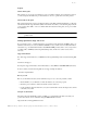
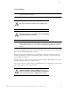
Preface Figure P-3 PSU/Cooling Module Caution Label: Do not operate with modules missing. A faulty power supply/cooling module must be replaced with a fully operational module within 24 hours. To ensure your system has warning of a power failure, disconnect the power from the PSU by either the switch (where present) or by physically removing the power source, Warning prior to removing the PSU from the enclosure.
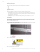
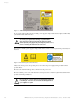
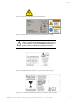
Preface Figure P-5 PSU Safety Label (Electric Shock Hazard Inside) Figure P-6 Redundant Power Input Switch Module Label (Hazardous Voltage) Operation of the product with ANY modules MISSING in the product’s chassis will disrupt airflow and the drives will not receive sufficient cooling. It is ESSENTIAL that all bays in a Warning product chassis are filled before operating the product.
Preface Class 1 Laser Product When the product is supplied with optical modules, it contain a laser that complies with Laser Class 1, US 21 QFR (J) & EN 60825-1, UL (NRTL) and TUV. Caution ! If optical modules are to be provided and fitted by the end user, the modules must be a UL (or other North American NRTL) RECOGNISED COMPONENT, must be approved by TUV (or other European Product safety test house), and the laser in the module must comply with Laser Class 1, US 21 QFR (J) & EN 60825-1.
Preface Taiwan Class A Electronic Emission Statement Japan VCCI Class A ITE Electronic Emission Statement Industry Canada Class A Emission Compliance Statement This Class A digital product complies with Canadian ICES-003. Avis de conformité à la réglementation d’Industrie Canada Cet appareil numérique de la classe A est conform à la norme NMB-003 du Canada.
Preface Korean Class A Electronic Emission Statement l Rack System Precautions The following safety requirements must be considered when the product is mounted in a rack. ! Do not slide more than one product enclosure chassis out of the rack at a time, to avoid the rack from toppling over.
Preface Taiwan Contact Information How to Send Your Comments Your feedback is important in helping us to provide the most accurate and high-quality information. If you have comments or suggestions for improving this publication, you can send us comments electronically by using the following address: Internet: starpubs@us.ibm.
Preface x IBM System Storage DCS9550 1S1 Storage Expansion Unit Installation, Service, and User Guide
Preface xi IBM System Storage DCS9550 1S1 Storage Expansion Unit Installation, Service, and User Guide
Contents Contents 1 Introduction ..................................................................................................................................... 1 The IBM System Storage DCS9550 1S1 Storage Expansion Unit 1 1.1.1 1.2.1 1.2.2 1.2.3 1.2.4 1.2.5 1.2.6 1.4.1 1.4.2 1.4.3 1.4.4 1.4.5 1.4.6 1.4.7 1.4.8 1.4.9 1.4.10 Enclosure Chassis .............................................................................................................. 2 Power Supply/Cooling Module .................
IBM System Storage DCS9550 1S1 Storage Expansion Unit Installation, Service, and User Guide 4.3.2 4.3.3 4.4.1 4.5.1 4.5.2 4.5.3 4.5.4 4.5.5 4.6.1 4.9.1 4.9.2 4.9.3 4.9.4 xiii Ops Panel ........................................................................................................................ SCM I/O Module LEDs ..................................................................................................... Audible Alarm Mute ..............................................................
Introduction 1 Introduction 1.1 The IBM System Storage DCS9550 1S1 Storage Expansion Unit . Figure 1–1 The DCS9550 SATA Disk Chassis Model 1S1 System The DCS9550 1S1 Storage Expansion Unit design concept is based on a subsystem together with a set of plug-in modules. The DCS9550 1S1 Storage Expansion Unit subsystem as supplied comprises: • Chassis and Backplane with integral.Operators Panel.
Introduction • Dummy drive carrier modules. • Two AC, 450W Power Supply/Cooling plug-in modules (see Figure 1–4) • One or two Serial ATA Control (SCM) Input/Output modules, dependent on configuration required: 1.5Gb internal operating speed with 1 Gb or 2Gb external operating speed. (See Figure 1–6). 1.1.
Introduction 1.2 The Plug-in Modules An DCS9550 1S1 Storage Expansion Unit requires one or more of the following modules for normal operation: 1.2.1 Power Supply/Cooling Module Two auto ranging AC 450WPower Supply/Cooling modules (Figure 1–4) are supplied mounted in the rear of the enclosure as part of the subsystem core product. Figure 1–4 . AC Power Supply/Cooling Module PSU voltage operating ranges are nominally 115V or 230V AC, selected automatically. .
Introduction 1.2.2 Operators Panel Supplied as an integral part of the Enclosure core product, a typical Operators (Ops) Panel is shown in Figure 1–5. Figure 1–5 Ops Panel The Ops Panel provides the enclosure with a micro controller which is used to monitor and control all elements of the Enclosure. 1.2.2.
Introduction Table 1–1 Ops Panel Switch Functions (Default settings for DCS9550 1S1 Storage Expansion UnitSCM usage at 2Gb/s) Switch Number Function *See Sw 11 Drive Loop Speed Select Recommended Setting Definition Sw 7 Sw 8 DCS9550 Controller Settings Off Off Force 1Gb/s DCS9550 Controller Settings On Off Force 2Gb/s (recommended) Sw 9 Sw 10 Off On Mode 1 On On Mode 0 On Off Mode 2 Off Off Mode 3 (not supported)* 7&8 Drive Addressing Mode Selection 9 & 10 DCS9550 Controller
Introduction Table 1–2 FC Host Port 1 Signal Good Incoming FC signal is GOOD No connection or incorrect connection Invalid SFP connection Green Router Status Storage Router Device Ready Storage Router Device not ready or defective Green ESI/SCM Module Fault Fault present (also On when booting) Successful controller initialization Amber Figure 1–6 6 SCM I/O Module LEDs On Off Flashing On Off Off On SCM I/O Module IBM System Storage DCS9550 1S1 Storage Expansion Unit Installation, Service
Introduction Figure 1–7 SCM Front Panel (as viewed from rear of Enclosure) Figure 1–8 DCS9550 1S1 Storage Expansion Unit with SCM I/O Modules Installed IBM System Storage DCS9550 1S1 Storage Expansion Unit Installation, Service, and User Guide 7
Introduction 1.2.4 Drive Carrier Module The Drive Carrier Module comprises a hard disk mounted in a carrier. Each drive bay can house a single Low Profile 1.0 inch high, 3.5 inch form factor disk drive in its carrier. The carrier has mounting locations for ATA or FC-AL drives. Each disk drive is enclosed in a die-cast aluminum carrier which provides excellent thermal conduction, radio frequency, and electro-magnetic induction protection and affords the drive maximum physical protection.
Introduction 1.2.4.3 Anti-tamper Locks Anti-tamper locks are fitted in the drive carrier handles (Figure 1–10) and are accessed through the small cutout in the latch section of the handle.These are provided to disable the normal ‘pinch' latch action of the carrier handle and so prevent accidental or unauthorized removal of drives. Figure 1–10 1.2.5 Anti-tamper Lock Dummy Carrier Modules Dummy carrier modules are provided for fitting in all unused drive bays.
Introduction 1.4 DCS9550 1S1 Storage Expansion Unit Technical Specification 1.4.1 Dimensions Rack Enclosure 1.4.2 1.4.3 1.4.4 inches millimeters Height 5.12 130 Width across mounting flange 19.0 482 Depth 19.7 500 Weight Fully loaded with 16 drives 37kg (77.6 lb) Empty Enclosure 9kg (19.8lb) AC Power (450W PSU) Voltage Range 100-120 / 200-240 VAC Rated Voltage Range Selection Automatic Frequency 50/60 Hz Inrush Current 50A @ 260VAC Power Factor >0.
Introduction 1.4.6 Environment Table 1–3 Ambient Temperature and Humidity Temperature Range Relative Humidity Max.
Introduction EN55022 (CISPR - A), FCC A • EMC 1.4.7 Interfaces Drive support See drive carrier specification Attachment 1 FCAL loop of 16 drives Passive Backplane with 1 or 2 Loop Resiliency Circuit (SCM) I/O Modules. Host Port: FC-AL SFP - SFP cables Maximum external cable length: see manufacturer’s specification Expansion Port: SFP to SFP cables 1.4.8 SCM I/O Module Specification Speed 1.
Introduction 1.4.10 Software Enclosure Services (SES) Support The enclosure has a sophisticated self-monitoring and reporting function which conforms to ANSI SES specifications.
Introduction This page is intentionally blank.
Installation 2 Installation In this chapter, you are shown how to install your DCS9550 1S1 Storage Expansion Unit and plug-in modules into an industry standard 19 inch rack cabinet. Caution 2.1 When connecting up the DCS9550 1S1 Storage Expansion Unit, use only the power cords supplied or cords which match the specification quoted in section 1.4.5.
Installation Table 2–1 DCS9550 1S1 Storage Expansion Unit Configuration Module Location Blank SCM I/O Modules Install in rear Bay 4. Ops Panel (integral part of chassis assembly). Installed in rear Bay 2. Caution Figure 2–1 2.1.1 Dummy Carriers and Blank Modules MUST be fitted to ALL unused bays. There is inadequate drive cooling if any are left open. Module locations Enclosure Bay Numbering Convention The enclosure bay numbering convention is shown in Figure 2–1.
Installation 2.2 Enclosure Installation Procedures Caution ! Warning 2.2.1 The DCS9550 1S1 Storage Expansion Unit with all its component parts installed is too heavy for a single person to easily install into a Rack cabinet. The following procedures describe the installation of the DCS9550 1S1 Storage Expansion Unit and highlights any critical co-requisite requirements and good handling practices which you should follow so as to ensure that a successful installation is achieved in the easiest manner.
Installation • Rack mount front flange mounting screws (4 off). 2.2.3.2 Procedure 1 Check for damage. 2 Slide the chassis assembly onto the rack rails until the front flanges engage on the rack. 3 Ensure the chassis is centrally located. If in doubt about correct orientation, the drive bays (at front) should have their black drive connectors toward the bottom of each bay. 4 Screw the 4 front rack mount screws through the flanges and tighten.
Installation Important Install the Power Supply/Cooling module (PSU 0) in the bay on the right side (Rear Bay 1) of the enclosure in an “upside down” orientation. If necessary, reorient the power cord clip so that the power cord can be properly retained. 3 Cam the module home by manually closing the PSU handle (Figure 2–4). You should hear a click as the handle latches engage. 4 Connect the power supply cord to the power source and switch the power supply ON.
Installation Figure 2–4 2.4 Installing an AC Power Supply Cooling Module (2) SCM I/O Module Configurations Important 2.4.1 Please refer to section 2.9 for information on SATA drive configurations. Internal Loop Structures The DCS9550 1S1 Storage Expansion Unit is configured with one internal loop of 16 drives. 2.5 FC-AL Interface The SCM (I/O) interface module provides an external FC-AL interface via SFP connection.
Installation 2.6 Cabling the IBM System Storage DCS9550 1S1 Storage Expansion Unit The following figures illustrates how to cable the DCS9550 1S1 Storage Expansion Unit to the couplets (Unit 1 and Unit 2) and the couplets to each other.
Installation Unit 2— A Unit 2— B Unit 2— C Unit 2— D Unit 2— E Unit 2— F Unit 2— G Unit 2— H Unit 2— P Figure 2–6 Unit 2— S 22 DCS9550 1S1 Storage Expansion Unit: Unit #2 Cabling IBM System Storage DCS9550 1S1 Storage Expansion Unit Installation, Service, and User Guide
Installation Figure 2–7 IBM System Storage DCS9550 Couplet Cabling 2.7 SCM I/O Module Installation Important 2.7.1 The SCM I/O modules must be installed in Rear Bay 3 and 4 location [see Figure 2–1, ”Module locations”, on page 16]. Procedure Check for damage especially to the interface connector. Do not install if any pins are bent. Figure 2–8 SCM Module Latch Operation 1 Install the module in rear Bay 3 of the enclosure (Figure 2–1).
Installation Figure 2–9 2.8 Installing an SCM I/O Module in Bay 4 Drive Enclosure Device Addressing Each enclosure has 16 drive bays. The SEL_ID of each drive is determined by the device slot (0-15) in which it is installed and the address range setting, which is set by means of the Enclosure ID switch on the Ops Panel (shown in Figure 1–2 on page 2) at the rear of the enclosure.
Installation Table 2–2 Ops Panel Switch Functions (Default settings for DCS9550 1S1 Storage Expansion Unit SCM usage at 1Gb/s) Switch Number Function 11 SOFT SELECT On 12 Not Used Notes Recommended Setting Definition Selects functions using the hardware switches Off 1 ON = switch to the left, OFF = switch to the right.
Installation ) Table 2–4 Drive Slot Arrangement: Enclosure Front View Row/ Column 1/# 2/# 3/# 4/# #/1 Drive 0* Drive 1 Drive 2 Drive 3 #/2 Drive 4 Drive 5 Drive 6 Drive 7 #/3 Drive 8 Drive 9 Drive 10 Drive 11 #/4 Drive 12 Drive 13 Drive 14 Drive 15* Notes 1 Drives are numbered row/column. 2 With only one active PSU the enclosure takes approximately 96 seconds to start all drives from Power On. 3 * Denotes SES drives which should always be fitted. 2.9 2.9.1 2.9.1.
Installation 2.10 2.10.1 Drive Carrier Installation Parts Check List • Drive Carrier module, or • Dummy Carrier module 2.10.2 Procedure 1 Ensure that the anti-tamper lock is disengaged. 2 Release the carrier handle by pressing the latch in the handle towards the right. 3 Insert the carrier into the enclosure (Figure 2–10). Important 4 For a Rack Mounted System: Ensure that the carrier is oriented so that the drive is uppermost and the handle opens from the left.
Installation 28 Figure 2–10 Installing a SATA Drive Carrier Module (1) Figure 2–11 Installing a SATA Drive Carrier Module (2) IBM System Storage DCS9550 1S1 Storage Expansion Unit Installation, Service, and User Guide
Installation Figure 2–12 Installing an SATA Drive Carrier Module (3) Note 2.10.3 Removal is the reverse of this procedure (press on the latch to release the handle). Dummy Carrier Modules Any unused drive bays must be fitted with a dummy carrier module. 2.10.4 Engaging the Anti-tamper Locks The anti-tamper locks are fitted in the drive carrier handles and are accessed through the small cutout in the latch section of the handle. Drives are supplied with the locks set in the locked position. 2.10.4.
Installation ). Figure 2–13 4 Activating the Anti-tamper Lock Remove the key. De-activation is the reverse of this procedure. To deactivate, rotate the key in an anticlockwise direction until the indicator is no longer visible in the aperture beside the key. Note 2.11 2.11.1 A drive carrier cannot be installed if its anti-tamper lock is activated outside the enclosure. Power Cord Connection Parts Check List • Power cord to requisite local standards 2.11.
Installation 2.12 Grounding Checks The product must only be connected to a power source that has a safety electrical earth connection. Warning If more than one product is fitted in a rack, the earth connection to the rack is even more important, because the rack will then have a high “EARTH LEAKAGE CURRENT” (“TOUCH CURRENT”).
Installation This page is intentionally blank.
Operation 3 Operation Before powering up the enclosure please ensure that all the modules are firmly seated in their correct bays. 3.1 Power On Caution Do not operate the subsystem until the ambient temperature is within the specified operating range. If the drives have been recently installed ensure they have had time to acclimatize before operating them. Note Please refer to Section h2-Heading for details of the Ops Panel LEDs and related fault conditions.
Operation 3.1.1 Power Supply/Cooling Module LEDs The Power Supply/Cooling module incorporates 4 LEDs, located below the On/Off switch and shown in tablecap. • Under Normal conditions the LEDs should all be illuminated constant GREEN • If a problem is detected the color of the relevant LED will change to AMBER.
Operation 3.2 Ops Panel LEDs The Ops Panel LEDs fault and status conditions are defined in Table 3-2 and shown in Figure 3-1. Figure 3–1 Ops Panel LEDs and Switches Please refer to Chapter 4, Troubleshooting and Problem Solving for details of any fault indication.
Operation Table 3–2 Ops Panel LED States 3.3 LED Definition Color Normal Status Fault Status 2Gb Link Speed Indicates link speed Green Off On Hub Mode Not Used Green Off Off Starting the Drives Unless otherwise selected during installation, all drives in the enclosure should automatically start their motors. If this has not occurred one of the following conditions may exist: • There may be a power problem (an alarm and power fault indication would normally be active).
4 Troubleshooting and Problem Solving The DCS9550 1S1 Storage Expansion Unit includes a processor and associated monitoring and control logic to enable it to diagnose problems within the enclosure’s power, cooling and drive systems. The Enclosure Services Processor is housed along with the Ops Panel in the rear of the enclosure. The sensors for power and cooling conditions are housed within the Power Supply/Cooling modules. There is independent monitoring for each unit.
Troubleshooting and Problem Solving 4.2.2 Alarm Sounds On Power Up Please refer to Section 4.4. 4.2.3 Green “Signal Good” LED on SCM Not Lit Check that the cables have not been reversed during installation. 4.2.4 Computer Doesn’t Recognize the DCS9550 1S1 Storage Expansion Unit 1 Check that the FC-AL interface cables from the DCS9550 1S1 Storage Expansion Unit to the host computer, or RAID controller, are fitted correctly.
Troubleshooting and Problem Solving Table 4–1 PSU LEDs AC PSU 4.3.2 LED Status • PSU Good Green • AC input Fail Amber • Fan Fault Amber • DC Output Fail Amber Ops Panel The Ops Panel displays the aggregated status of all the modules. The Ops Panel LEDs are shown in Figure 4–1 and defined in Table 4–2. For details on how to remove and replace a module see Section 4.9. Note Figure 4–1 The Ops Panel is supplied as an integral part of the Enclosure core product and is not user replaceable.
Troubleshooting and Problem Solving Table 4–2 Ops Panel LED States 40 LED Definition Color Normal Status Fault Status Invalid Address Indicates that an invalid Amber Off Enclosure ID has been selected or that the selection has changed after Power On Flashing Power On Enclosure Powered On Green On Off System Fault System/SCM Fault Amber Off On PSU/Cooling Fault PSU Cooling fault or enclosure over-temperature.
Troubleshooting and Problem Solving 4.3.3 SCM I/O Module LEDs The SCM I/O module LEDs are shown in Table 4–3. Table 4–3 SCM I/O Module LEDs LED 4.
Troubleshooting and Problem Solving 4.5 Troubleshooting The following sections describe common problems, with possible solutions, which can occur with your DCS9550 1S1 Storage Expansion Unit 4.5.1 System Faults Symptom Cause 1 The SYSTEM LED will The ESI illuminate AMBER on processor has detected an the SCM internal fault (e.g. failure of an 2 Audible Alarm sound internal communications path) Action 1 Check for other AMBER LED indications on the Power Supply/Cooling modules.
Troubleshooting and Problem Solving 4.5.3 Thermal Control The DCS9550 1S1 Storage Expansion Unit uses extensive thermal monitoring and takes a number of actions to ensure component temperatures are kept low and also to minimize acoustic noise. Air flow is from front to rear of the enclosure. Symptom Cause If the ambient air is cool (below 25 °C) and the fans are observed to increase in speed then some restriction on airflow may be causing additional internal temperature rise.
Troubleshooting and Problem Solving 4.5.4 Thermal Alarm Cause Symptom 1 Ops Panel FAULT LED AMBER. 2 An AMBER LED on one or more Power Supply/Cooling Modules. Action If the internal temperature measured in the airflow through the enclosure exceeds a preset threshold a thermal alarm will sound. 3 Audible Alarm Sounding. 1 Check local ambient environment temperature is below the upper 40°C specification. 2 Check the installation for any airflow restrictions at either the front or rear of the enclosure.
Troubleshooting and Problem Solving 4.6.1 Dummy Carrier Modules Dummy Carrier modules must be fitted to all unused drive bays to maintain a balanced air flow. 4.7 Dealing with Hardware Faults Ensure that you have obtained a replacement module of the same type before removing any faulty module. ATTENTION If the DCS9550 1S1 Storage Expansion Unit is powered up and you remove any module, replace it immediately.
Troubleshooting and Problem Solving 4.9.1 Danger 4.9.1.1 Power Supply/Cooling Modules Do not remove covers from the Power Supply/Cooling (PSU) module. Danger of electric shock inside. Return the PSU to your supplier for repair. Removing a Power Supply/Cooling Module ATTENTION Do not remove the faulty Power Supply/Cooling module unless you have a replacement unit of the correct type ready for insertion. If a power supply unit or its fan is faulty, you must replace the whole Power Supply/Cooling module.
Troubleshooting and Problem Solving Figure 4–2 Removing/Inserting an AC Power Supply/Cooling Module (1) Figure 4–3 Removing/Inserting an AC Power Supply/Cooling Module (2) IBM System Storage DCS9550 1S1 Storage Expansion Unit Installation, Service, and User Guide 47
Troubleshooting and Problem Solving Figure 4–4 4.9.2 Removing/Inserting an AC Power Supply/Cooling Module (3) Ops Panel The Ops Panel is an integral part of the enclosure chassis assembly and is not field replaceable. 4.9.3 SCM I/O Module Please refer to section 2.7, ”SCM I/O Module Installation”, on page 23 for full information on installing the SCM I/O module. 4.9.3.1 Removing the Module ATTENTION Do not remove this module unless a replacement can be immediately added.
Troubleshooting and Problem Solving Figure 4–5 Removing an SCM I/O Module (1) Figure 4–6 Removing an SCM I/O Module (2) IBM System Storage DCS9550 1S1 Storage Expansion Unit Installation, Service, and User Guide 49
Troubleshooting and Problem Solving 4.9.3.2 Inserting the Module ATTENTION If only one SCM module is fitted, it must be installed in Module B location (Rear Bay 4) [see Figure 2–1, ”Module locations”, on page 16] and an I/O blank module fitted in the unused bay. 1 With the latch in the open position, slide the SCM I/O module into the enclosure until the latch engages automatically. 2 Cam the module home by manually closing the latches (see Figure 4–7).
Troubleshooting and Problem Solving 3 4.10 Withdraw the module from the drive bay and fit a replacement module in accordance with the instructions in Section 2.9.
Troubleshooting and Problem Solving This page is intentionally blank.
Glossary Glossary In glossary definitions, italics are used for items defined elsewhere in the glossary and bold is used for the items shown in brackets after the main heading of the entry. ASCII American Standard Code for Information Interchange. A 7-bit binary code (0's, 1's) used to represent letters, numbers, and special characters such as $,!, and /. Supported by almost every computer and terminal manufacturer.
Enclosure The chassis assembly which houses the plug-in modules that make up the DCS9550 1S1 Storage Expansion Unit. ESI/Ops module A unit used to monitor and control all elements of the Enclosure. The ESI/Operators (Ops) panel is supplied as an integral part of the RS-1602 series Enclosure core product Hot plugging A device with the capability of being connected to a subsystem without interrupting the power supplies to that subsystem.
Index Index a f AC PSU 2, 3 Alarm Mute push-button 9, 41 anti-static wrist or ankle strap 17 anti-tamper lock 9, 29, 50 ATA SMART data 37 Audible Alarm 4, 9, 41, 42, 44 b Backplane 1, 2, 17, 45, 50 bay 15, 16 blank I/O module 9 fan failure 42 FC_AL signal 38 l LED 3, 4, 9, 38, 41, 42, 44 LED indicators 5 o Operators Panel 1, 4 Ops Panel 4, 9, 16, 17, 33, 39, 41, 42, 48 Ops Panel LEDs 35, 39 Ops Panel Switch Functions 4, 24 c chassis 2, 18 p d PATA disk drive 5 PATA/SATA disk drive 37 plug-in modul
IBM System Storage DCS9550 1S1 Storage Expansion Unit Installation, Service, and User Guide Serial ATA Control (SCM) Input/Output module 2 serial ATA protocol 20 SES 26 starting drives 36 SYSTEM LED 42 v Visible and Audible Alarms 56 9
Notices This information was developed for products and services offered in the U.S.A. IBM may not offer the products, services, or features discussed in this document in other countries. Consult your local IBM representative for information on the products and services currently available in your area. Any reference to an IBM product, program, or service is not intended to state or imply that only that IBM product, program, or service may be used.
estimated through extrapolation. Actual results may vary. Users of this document should verify the applicable data for their specific environment. Information concerning non-IBM products was obtained from the suppliers of those products, their published announcements or other publicly available sources. IBM has not tested those products and cannot confirm the accuracy of performance, compatibility or any other claims related to non-IBM products.
of life per this Directive. In accordance with the European WEEE Directive, electrical and electronic equipment (EEE) is to be collected separately and to be reused, recycled, or recovered at end of life. Users of EEE with the WEEE marking per Annex IV of the WEEE Directive, as shown above, must not dispose of end of life EEE as unsorted municipal waste, but use the collection framework available to customers for the return, recycling and recovery of WEEE.
60 IBM System Storage: DCS9550 1S1 Storage Expansion Unit Installation, Service, and User Guide
Readers’ Comments — We’d Like to Hear from You IBM System Storage DCS9550 1S1 Storage Expansion Unit Installation, Service, and User Guide Publication No. SC30-9738-00 We appreciate your comments about this publication. Please comment on specific errors or omissions, accuracy, organization, subject matter, or completeness of this book. The comments you send should pertain to only the information in this manual or product and the way in which the information is presented.
SC30-9738-00 ___________________________________________________________________________________________________ Readers’ Comments — We’d Like to Hear from You Cut or Fold Along Line _ _ _ _ _ _ _Fold _ _ _and _ _ _Tape _ _ _ _ _ _ _ _ _ _ _ _ _ _ _ _ _ _ _ _ _ _ _ _ _ _ _Please _ _ _ _ _do _ _not _ _ staple _ _ _ _ _ _ _ _ _ _ _ _ _ _ _ _ _ _ _ _ _ _ _ _ _ _ _ _ _Fold _ _ _and _ _ Tape ______ NO POSTAGE NECESSARY IF MAILED IN THE UNITED STATES BUSINESS REPLY MAIL FIRST-CLASS MAIL PERMIT NO.
Printed in USA SC30-9738-00