Asynchronous Color Terminals WS525 User Guide Order Number: EK-WS525-IN.
April 1994 PUBLICATION ISSUED BY: Ing. C. Olivetti & C., S.p.A. Direzione Documentazione Via Jervis, 77-10015 Ivrea (To) Copyright © 1994 by Ing. C. Olivetti & C., S.p.A. All Rights Reserved. Notice: The information contained in this document is subject to change without any previous notice. Ing. C. Olivetti & C., S.p.A. shall not be liable for errors contained herein or for incidental or consequential damages in connection with the furnishing, performance, or use of this material.
Contents Preface . . . . . . . . . . . . . . . . . . . . . . . . . . . . . . . . . . . . . . . v 1 Installation and Set-Up 1.1 1.2 1.3 Installation . . . . . . . . . . . . . . . . . . . . . . . . . . . Set-Up . . . . . . . . . . . . . . . . . . . . . . . . . . . . . . . Using Color . . . . . . . . . . . . . . . . . . . . . . . . . . . 1–2 1–4 1–9 2 Multiple Sessions 2.1 2.2 2.2.1 2.2.2 2.3 Overview . . . . . . . . . . . . . . . . . . . . . . .
Defining Keys 4.1 4.1.1 4.1.2 Define Key Editor . . . . . . . . . . . . . . . . . . . . . . Creating a New Function . . . . . . . . . . . . . . Creating a Key Sequence . . . . . . . . . . . . . . 4–1 4–2 4–3 A Maintenance and Troubleshooting A.1 A.2 A.3 Cleaning your Video Terminal . . . . . . . . . . . . . Troubleshooting . . . . . . . . . . . . . . . . . . . . . . . . Installing the ROM Cartridge . . . . . . . . . . . . .
Preface Overview This guide is for users who want to install and configure the WS525 video terminal. This guide describes how to connect cables and enter the Set-Up menu to make changes, as needed. This guide also has reference tables for troubleshooting, specifications, and compose sequences. For more detailed information on programming the terminal, refer to the VT520/VT525 Video Terminal Programmer Information.
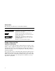
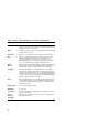
Conventions The following conventions are used in this document: Convention Caps Lock Lock Meaning Print Screen 0 Caps Lock Alt F11 kpd Indicates two keys that you must press in combination. Press and hold the first key while you press the second key. Indicates two keys that you must press in sequence. Press and release the first key before you press the second. Indicates three keys that you must press in combination, holding the first two down while pressing the third.
Table 1 Recommendations for Proper Setup and Use Adjust So that your . . . Chair 1 Feet are flat on the floor or footrest, if needed. 2 Legs are vertical forming a right angle to the floor. 3 Weight is off your thighs and are in a horizontal position. Keep the back of your knees away from the seat so you do not compress the area behind them, which could restrict the blood flow. 4 Upper body is erect and your lower back is supported with a backrest.
Table 1 (Cont.) Recommendations for Proper Setup and Use Adjust To . . . 6 Keep your upper arms straight down at your sides, elbows close to your sides to support your arm weight. Forearms should be at a 70° to 90° angle. Head 7 Avoid neck strain. Your head should incline downward, but no more than 15° to 20°. Terminal 8 Keep eye level and the correct distance for proper vision.
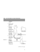
1 Installation and Set-Up If desired, install the system box in its stand. The WS525 comes with a stand. You can use the system box without the stand under your monitor, or you can install the system box in the stand. Instructions are illustrated on the stand. A wire clip is included to dress the cables neatly along the back of the system box.
Installation and Set-Up 1.1 Installation 1.1 Installation Connect the cables to the system box. 5 7 6 K 4 3 2 AC Comm 1, Comm 2, Comm 3 (Serial printer), Keyboard, Kensington lock socket, Parallel printer, Monitor 1 Connect the cables to the monitor. Check your monitor manual for correct installation. Push the system box and monitor power switches on. A green light in the switch indicates that power is on.
Installation and Set-Up 1.1 Installation Keyboards Figure 1–1 ANSI-Style Keyboard Layout No rt h A m erican /U n it ed K in g d o m ( Wo rd P r ocessing V er sion) F5 F6 ! a # $ % 1 2 3 4 5 Q Tab W A Ctrl > < Shift Compose Character E S R D Z Y G U H V B F10 * 8 7 T C F9 & ^ 6 F X F8 F7 F11 ( ) 9 0 I J K N - O Alt Function Alt Function Help F14 X } ] : ; > .
Installation and Set-Up 1.2 Set-Up 1.2 Set-Up Overview Use Set-Up to examine or change the terminal operating features. The Set-Up menu summary at the bottom of the screen are the communication features to get you started in operating the terminal. There are many more Set-Up features in the terminal that you may wish to change. Before changing the communication Set-Up features, contact your System Manager if necessary.
Installation and Set-Up 1.2 Set-Up Moving within a Set-Up Menu Use the arrow keys ( , , , within a list, or to select buttons. In a menu . . . ) to move among the menus or Indicates . . . A pull-right submenu is available. ... A dialog box is available for you to specify more information. a b c The menu item with the filled-in circle is enabled. Only one of these items can be enabled at a time. The menu item with the checkbox is enabled.
Installation and Set-Up 1.2 Set-Up Select the Set-Up language. This language selection is for Set-Up only and does not affect keyboard, character set, or printer settings. As you make changes to some Set-Up parameters, the Set-Up summary line will reflect those changes. 1 2 4 3 5 Port selected, Transmit speed (9600), Parity (N), Word size (8), Stop bits (1), Character set, Keyboard language, Emulation mode, Firmware version.
Installation and Set-Up 1.2 Set-Up Configuration The WS525 allows you to open up to four sessions depending on the communications connections and the host software. As a minimum for each session (S1, S2, S3, and S4), determine the following menu items, and note any change here that you make from the default value. Menu item Default Terminal type Emulation mode VT525 Keyboard language English Keyboard Communication Port select See Figure 1–3.
Installation and Set-Up 1.2 Set-Up Notes For a session to be enabled, it must be assigned to a comm port. If you assign more than one session to the same comm port, you must use a terminal server that supports Terminal Device Session Management Protocol (TD/SMP), or a host that supports Session Support Utility (SSU). A port cannot be assigned as both a comm port and a printer port at the same time. Selecting Comm = ‘‘ none’’ disables a session.
Installation and Set-Up 1.3 Using Color 1.3 Using Color You can control the terminals display colors. You may choose color settings to match your software, to emulate another terminal, or to suit your preference. Depending on the settings you choose, for each session you can assign colors for various text uses and defined a map of 16 colors (8 text and 8 background) from a larger palette of 4096 colors. Changes in color selections become visible upon entering new text and when the screen is refreshed.
Installation and Set-Up 1.3 Using Color From the Color submenu in Set-Up, choose . . . If you want to . . . Choose the window frame and icon colors Assign colors . . . Erase text to the text background color (PC style) Erase color Erase text to the screen background color (ANSI style) Erase color Text background. Screen background. Save your settings. Use one of the following procedures: Save . . . Select menu item . . .
2 Multiple Sessions 2.1 Overview Multiple sessions extend the WS525 to act like four terminals in one. A session is an active connection between the terminal and a host system. See Figure 1–3. The WS525 supports up to four sessions using virtual terminals. Each virtual terminal maintains the full keyboard and display state of a real physical terminal but shares a single keyboard and display with other virtual terminals. Before you can login using a virtual terminal, it must be connected to a host computer.
Multiple Sessions 2.2 Using a Terminal Server with TD/SMP 2.2 Using a Terminal Server with TD/SMP At the Local> prompt, enter the following command: Local> set port multi enable Return Continue with your login procedure. To permanently set a terminal server port to use TD/SMP, type: Local> define port multi enable Return 2.2.
Multiple Sessions 2.3 Tips for Using Multiple Sessions 2.3 Tips for Using Multiple Sessions • You can display data from two sessions at the same time by dividing the screen into two windows. Press Ctrl F4 (Session) or Ctrl Caps Lock 0 kpd to change the window configuration. • When you choose Display Framed windows, you can assign a 30-character name to each session for the window title bar. The first 12 characters of the session name become the session icon name.
3 Desktop Features 3.1 Invoking Desktop Features Overview From the Actions menu, you can invoke Clock, Calculator, Show character sets and the Banner message. When the feature is highlighted (displayed in reverse video), press Enter or Return to enable the feature. A quick start summary of some keyboard features is provided, as well as how to implement the Accessibility Aid feature and the Copy and Paste function.
Desktop Features 3.1 Invoking Desktop Features 3.1.1 Clock feature You can enable the Clock feature without entering Set-Up by pressing Caps Lock Alt F11 if you are either in a VT or an SCO console emulation mode. The current time is displayed in the status line if this feature is enabled. The format is HH:MM, followed by AM or PM if the 12-hour format is selected. Use the following keys within the clock feature: Key Function or Tab Go to next field. or Shift Tab Go to previous field.
Desktop Features 3.1 Invoking Desktop Features 3.1.2 Calculator feature If you are either in a VT or an SCO console emulation mode, you can enable the Calculator feature without entering Set-Up by pressing Caps Lock Alt F12 . In addition to the numbers on the numeric keypad, you can use the following keys with the calculator: Key H , O , or D Function Selects hexadecimal H , octal O , or decimal D format. Arrow keys Move the position of the calculator on the screen.
Desktop Features 3.1 Invoking Desktop Features 3.1.3 Show Character Sets feature If you are in either a VT or an SCO console emulation mode, you can enable the Show character sets desktop feature without entering Set-Up by using Caps Lock Alt F10 . When the character set is displayed, you can use the following keys with this feature: Key Function Next or Prev Page Up or Page Down Looks through the available character sets. Shift A Restores the character set.
Desktop Features 3.2 Keyboard Summary 3.2 Keyboard Summary The following table provides a quick start summary of some keyboard features. To . . . ANSI Keyboard, press . . . Hold the screen F1 Scroll Lock Print the screen F2 Print Screen Enter/Exit Set-Up F3 Caps Lock Switch session F4 or Caps Lock 0 Caps Lock 0 kpd Select specific session Caps Lock 1, 2, 3, or 4 Break F5 Toggle split screen Ctrl F4 PC Keyboard, press . . .
Desktop Features 3.2 Keyboard Summary Accessibility aid This feature allows a user with limited motor skills to use modifier key combinations in a sequential manner rather than in a simultaneous manner. All modifier key combinations are supported. There are two operation states—Latch and Lock. The Latch state affects only the next key pressed. When in the Lock state, all keys pressed are affected by the modifier until you press the same modifier key again or press any other modifier key twice.
4 Defining Keys 4.1 Define Key Editor Overview This terminal provides a powerful Define Key Editor that allows you to modify the function of keys on your keyboard. Since keystrokes can perform many different functions, it will take some practice to understand how the keys work. This section is an introduction to customizing your keyboard. Moving Standard Functions The simplest way to re-program a key is to copy the behavior of another key.
Defining Keys 4.1 Define Key Editor Function Keys Function keys are used to transmit function key sequences or to perform local terminal functions such as the arrow keys ( , , , ), the Shift modifier key, or the key that calls up the Set-Up menu (F3). A User Defined Key (UDK) is a special function key. Modifier Keys A modifier key is a key that modifies the behavior of other keys when it is pressed and held down.
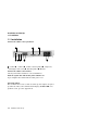
Defining Keys 4.1 Define Key Editor Figure 4–1 Define Key Editor, Select Function MA−0324−93.GRA 6. Repeat steps 4 and 5 to define other modifier sequences. 7. Choose the OK or Apply button and press Example: Disabling the Compose , them to have no function. Break , or Enter . Set-Up key by assigning 4.1.2 Creating a Key Sequence To define a key sequence: 1. From the Keyboard menu item, select the Define key . . . function, and the Define Key Editor menu will appear. 2.
Defining Keys 4.1 Define Key Editor 5. Enter a key sequence, such as a print queue. Example: Print my file 6. Press the key to select where the sequence is to be sent: Normal To video screen and/or host depending on communication setting (on-line, half-duplex, local). Terminal only To video screen only. Host only To central host computer. 7. Choose the OK or Apply button. NOTE Pressing the Set-Up key to exit Set-Up will activate the OK button to keep any changes you have made.
A Maintenance and Troubleshooting A.1 Cleaning your Video Terminal Cleaning the Screen Before cleaning the screen, set the terminal power switch to the off position and wait 20 seconds to let static electricity dissipate. Clean the screen with a video screen cleaner. Cleaning the Keyboard If needed, wipe the keys with a soft cloth. Do not allow moisture to get under the keys. A.
Maintenance and Troubleshooting A.2 Troubleshooting Troubleshooting Table Use Table A–1 to identify and correct any problem areas. Table A–1 Identifying and Correcting Problems Symptom Possible Cause Suggested Solution The printer will not print. Communication port is not set correctly. From the Communication menu item, choose Port select and match the connections on the terminal. If you have a serial printer, its speed may be set incorrectly.
Maintenance and Troubleshooting A.2 Troubleshooting Table A–1 (Cont.) Identifying and Correcting Problems Symptom Possible Cause Suggested Solution Green color is missing. Green signal cable has a loose connection or is not connected to the terminal. Check the cable connections. A.3 Installing the ROM Cartridge Introduction This terminal can accommodate an optional ROM cartridge in its system box.
Maintenance and Troubleshooting A.3 Installing the ROM Cartridge If you are having the terminal serviced, then remove and save the ROM cartridge. To restore the firmware from the ROM cartridge: 1. Turn the power on and press 2. Select Actions F3 . Restore factory defaults and press 3. Select Save settings and press A–4 Maintenance and Troubleshooting Return . Return .
B Specifications System Unit The following are the specifications for the WS525 system unit. Dimensions With Stand Without Stand Height 34.3 cm (13.5 in) 5.0 cm (2.0 in) Width 5.7 cm (2.25 in) 29.5 cm (11.6 in) Depth 31.8 cm (12.5 in) 32.4 cm (12.75 in) Weight 16.5 Kg (7.5 lbs) 14.3 Kg (6.5 lbs) Operating Systems Supported UNIX, MDOS, OpenVMS, OSF, ULTRIX, VMS, or any other that supports ASCII or ANSI protocols.
Specifications Electrical Requirements AC input voltage 101, 110, 120, 220, 230, 240 Vac auto-sensing single phase, 3-wire Line frequency 47 Hz to 63 Hz Power consumption 15 watts maximum Operating Temperature 10°C to 40°C (50°F to 104°F) Humidity 10% to 90% relative humidity Maximum wet bulb = 28°C Minimum dew point = 2°C (noncondensing) Monitor Requirements The WS525 requires a multisync monitor that supports VGA 72 Hz (37.8 KHz horizontal scan rate), with a 15-pin, D-Sub connector.
Specifications Compose characters Compose character are available in Multinational, ISO Latin 1, ISO Latin 2, ISO Latin-Greek, and National Replacement character sets (NRCS) for ANSI keyboards, except Canadian-English, Danish, Dutch, Hebrew, Hungarian, Italian, Norwegian, Polish, Romanian, Russian, SCS, Turkish-F, Turkish-Q, UK, and US keyboards. Nonvolatile memory 970K bytes memory User-defined key maximum length = 255 bytes. Power Cords Order Number Country Amp Length COR041 Switzerland 15A 2.
Specifications Figure B–1 Comm1—Serial Communication/Printer Ports CCITT/EIA/DIN 1 14 13 25 13 1 GND 2 TXD L 3 RXD L 4 RTS 5 CTS 6 DSR 7 SIG GND 8 CD 12 SI 20 DTR 23 SPD SEL L 9−11, 13−19, 21, 22, 24, 25 25 14 1 M F 103/BA/D1 104/BB/D2 105/CA/S2 106/CB/M2 107/CC/M1 102/AB/E2 109/CF/M5 112/CI 108.2/CD/S1.2 111/CH/S4 NC1 MA−0019−93.GRA 1 NC = not connected. Figure B–2 Comm2 and Comm3—MMJ Ports 1 6 1 2 3 4 5 6 DTR TXD L GND COM RXD L DSR MA−0020−93.
Specifications Standards Conformance Acoustic Noise Preliminary declared values per ISO 9296 and ISO 7779: Sound Power Level L Product 1 , B Sound Pressure Level2 L , dBA Idle Operate Idle Operate WS525 <3.9 <3.9 <20 <20 ANKPC 510 NA 6.0 NA 51 ANK 510 NA 5.6 NA 52 1 Current values for specific configurations are available from service representatives. (1 B = 10 dBA.) 2 Operator position.
Specifications Table B–1 (Cont.) Standards Conformance and Approvals Type Standard Subject CE Class B (EN55022 Class B, EN50082-1 Class 1) EN60555-2 Radio Protection Mark CE label ITE Class 2 (Japan) VCCI Electromagnetic compatibility Energy "Energy Star" EPA Energy Star requirements Ergonomic ZH1/618, GS-VS-SG7, TÜV Ergonomic Requirements Safety CSA 22.
Specifications EMI Requirements for Canadian Market This equipment does not exceed the Class B limits for radio noise emissions from digital apparatus as set out in the Radio Interference Regulation of the Canadian Department of Communications. Asbestos Asbestos is not used in this product or in its manufacturing process.