ERserver iSeries Networking iSeries Communications Management
ERserver iSeries Networking iSeries Communications Management
© Copyright International Business Machines Corporation 1998, 2001. All rights reserved. US Government Users Restricted Rights – Use, duplication or disclosure restricted by GSA ADP Schedule Contract with IBM Corp.
Contents Part 1. Getting started with AS/400 communications . . . . . . . . . . . . . . 1 Chapter 1. Print this topic . . . . . . . . . . . . . . . . . . . . . . . . . . . . . 3 Chapter 2. Configuring AS/400 for communications Creating a network interface description . . . . . Creating a network server description . . . . . . Creating a line description. . . . . . . . . . . . . . . . . . . . . . . . . . . . . . . . . . . . . . . . . . . . . . . . . . . . . . . . . . . . . . . . . . . . . . .
Matching AS/400 parameters for a 5494 connected by frame relay Matching AS/400 parameters for a 5494 connected by SDLC . . Matching AS/400 parameters for a 5494 connected by X.21 . . . Matching AS/400 parameters for a 5494 connected by X.25 . . . Matching AS/400 parameters for 3x74 controller . . . . . . . . Matching AS/400 parameters for a 3174 controller . . . . . . Matching AS/400 parameters for a 3274 controller . . . . . . Matching AS/400 parameters for finance controllers . . . . . . .
Part 1. Getting started with AS/400 communications The AS/400 is an extremely versatile system for networking technologies, supporting a broad range of communication protocols. Protocols that are supported include TCP/IP, APPC, APPN, HPR, Remote workstation, asynchronous, and binary synchronous communications. AS/400 communications configuration is done by either manually or automatically creating a set of configuration objects that represent the local and remote systems that are to communicate.
2 Version 5
Chapter 1. Print this topic To view or download the PDF version, select Getting started with AS/400 communications (about 721 KB or 110 pages). To 1. 2. 3. 4. 5. save a PDF on your workstation for viewing or printing: Open the PDF in your browser (click the link above). In the menu of your browser, click File. Click Save As... Navigate to the directory in which you would like to save the PDF. Click Save.
4 Version 5
Chapter 2. Configuring AS/400 for communications Follow these steps to configure your AS/400: 1. Depending on the type of hardware you have, you may need to refer to the following topics: v Creating a network server description v Creating a network interface description 2. You define lines by creating line descriptions. Depending on your hardware, the lines may be attached to a network server, or a network interface.
6 Version 5
Chapter 3. Optimizing communications performance Many factors can affect the performance of AS/400 application programs. To achieve the best performance with your particular communications environment, you may want to review these topics: v Improving wide area network (WAN) performance. v Improving local area network (LAN) performance. v Improving data path performance.
v For interactive environments, keep line use below 30% to maintain predictable and consistent response times. Exceeding 50% line use usually slows down response time. The line use can be measured with the AS/400 performance tools. v For large transfer environments, or for environments in which only a small number of users are sharing a line, increase line use to allow for acceptable response times.
processing a larger frame is only slightly more than the amount needed to process a smaller frame. If you use larger frames to transfer a single system message or block of data, decreases the total number of frames required to complete the transfer. v The values for IOP use in synchronous data link control (SDLC) environments do not necessarily increase consistently with the number of work stations or with the workload. An IOP can spend more time polling when the application is not using the line.
parameter value on one system should never have a greater value than the LANMAXOUT parameter value on the other system. The parameter values of the sending system should match the values on the receiving system. v Setting appropriate values for the LANMAXOUT parameter along with the LAN acknowledgment frequency (LANACKFRQ) parameter for both the sending stations and receiving stations is essential for optimal performance.
v Mix interactive and batch jobs on a wide area network line v Performance considerations for AnyNet communications v Subsystems Considerations for subsystem configuration for error recovery performance Each piece of work that runs on the AS/400 system is called a job. Each job is a single, identifiable sequence of processing actions that represents a single use of the system. The basic types of jobs performed are interactive jobs, batch jobs, spooling jobs, autostart jobs, and prestart jobs.
Example: Communications subsystem configuration 1. Create a duplicate of QCMN: CRTDUPOBJ OBJ(QCMN) FROMLIB(QSYS) OBJTYPE(*SBSD) TOLIB(MYLIB) NEWOBJ(MYCMN) 2. Set up the communication entries: ADDCMNE SBSD(MYLIB/MYCMN) DEV(PC*) ADDCMNE SBSD(MYLIB/MYCMN) DEV(PC*) MODE(QSERVER) MAXACT(0) ADDCMNE SBSD(QSYS/QCMN) DEV(PC*) MODE(QPCSUPP) MAXACT(0) 3. If desired, update your system startup program to start your new subsystems automatically.
Example: Interactive subsystem configuration 1. Create a subsystem description: CRTSBSD SBSD(MYLIB/MYINTER) POOLS((1 *BASE) (2 *INTERACT)) 2. Create a class CRTCLS CLS(MYLIB/MYCLASS) RUNPTY(20) 3. add routing entries to your subsystem: ADDRTGE SBSD(MYLIB/MYINTER) SEQNBR(10) CMPVAL(QCMDI) PGM(QSYS/QCMD) POOLID(2) ADDRTGE SBSD(MYLIB/MYINTER) SEQNBR(9999) CMPVAL(*ANY) PGM(QSYS/QCMD) POOLID(2) 4.
v Change the request/response unit size to a lower value for the large transfer. This parameter setting optimizes response time at the expense of large transfer performance. v Reduce the pacing values for the large transfer to slow it down, which allows the interactive users more windows for getting on the line. Note: The overall central processing unit time increases for the large transfer. For more information about AS/400 communications, see the Communications Configuration book.
are written for one type of network protocol to run over a different type of network protocol. For example, without AnyNet, your choice of application program interface (API) dictates your choice of network protocol, or your choice of network protocol dictates your choice of APIs. AnyNet allows you to mix and match applications with network protocols. In fact, you can do this without changing your application programs.
For more information about creating subsystems, see the Work Management 16 Version 5 book.
Chapter 4. Communications applications Communications applications that are used in an APPC (advanced program-to-program) environment are also available to be used in an APPN and HPR environment; only the method by which data is transported is changed. APPC delivers the data from applications higher in the SNA layers down to APPN for transportation through the network. User-written APPC applications and distributed data management (DDM) are fully supported in an APPN and HPR environment.
v Using larger sends for a given large transfer (record sizes) provides a higher application data rate and decreases CPU time. With the larger record size, the CPU has less processing to do because there are fewer application reads and writes to transfer the same amount of data. v If a value of *CALC is selected for maximum Systems Network Architecture (SNA) request/response unit (RU), the system selects an efficient size compatible with the frame size.
Performance considerations for Common Programming Interface Communications You can use Common Programming Interface Communications (CPI Communications) to write application programs that you want to communicate with advanced program-to-communications (APPC). The interface makes use of the System Network Architecture (SNA) LU (logical unit) 6.
20 Version 5
Chapter 5. Communicating with host systems You can configure the AS/400 system to communicate with a host system by matching AS/400 parameters. Another option for AS/400 users is Dependent LU Requester Support (DLUR). DLUR allows dependent secondary logical units (LU 0, 1, 2, and 3) an entry point into the APPN network. DLUR support gives the appearance of having an adjacent connection to VTAM, but allows traversing the APPN network through intermediate nodes.
AS/400 Prompt AS/400 Parameter Local adapter address ADPTADR Host Definition Statement PATH Host Parameter DIALNO Host DIALNO parameter is a concatenation of: SSAP/DSAP/remote-adapter-address. AS/400 CRTLINTRN command ADPTADR value must match the remote-adapter-address portion of the host DIALNO parameter. The DSAP portion of the DIALNO parameter must correspond to the SSAP value specified on the AS/400 controller description.
Matching AS/400 controller description parameters for a host system You must match host system communications configuration parameters with AS/400 values. A description of the AS/400 values are in the following table. For information about configuring host systems, see the manuals VTAM Installation and Resource Definition, SC23-0111, and Network Control Program Resource Definition Reference, SC30-3254.
AS/400 Prompt Maximum frame size AS/400 Parameter MAXFRAME Host Definition Statement GROUP Host Parameter MAXDATA Values specified for each system must match. Remote control point name RMTCPNAME VTAMLST SSCPNAME Required only if APPN(*YES). AS/400 controller description value must match SSCPNAME specified in the Virtual Telecommunications Access Method (VTAM) start options list (ATCSTRyy). Remote network identifier RMTNETID VTAMLST NETID Required only if APPN(*YES).
v Use the following table for the device description parameter. AS/400 Prompt Local location name AS/400 Parameter LCLLOCNAME Host Definition Statement DFHTCT Host Parameter NETNAME AS/400 LCLLOCNAME value must match CICS/VS terminal control table NETNAME parameter and the label used on the LU definition statement. Local location address LOCADR LU LOCADDR Values specified for each system must match.
AS/400 Prompt Mode description name AS/400 Parameter MODD Host Definition Statement MODEENT Host Parameter LOGMODE AS/400 mode description name specified on the AS/400 CRTMODD command (MODD parameter) must be defined in the host logon mode table using the LOGMODE parameter on the MODEENT macro instruction. The mode name must also be included in the CICS/VS terminal control table (DFHTCT) MODENAM parameter.
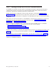
Example 2: AS/400 to host system over a token-ring line. This diagram shows the AS/400 values that need to match the VTAM values when you use a token-ring line. Chapter 5.
Example 3: AS/400 system for DLUR support with the host system.
This diagram shows the AS/400 values that need to match the VTAM values when you use AS/400 DLUR and VTAM. Example 4: AS/400 with APPN connection to VTAM This diagram shows the AS/400 values that need to match the VTAM values when you connect with APPN. Chapter 5.
30 Version 5
Configuring dependent LU requester (DLUR) Dependent LU Requester (DLUR) allows dependent secondary logical units (LU 0, 1, 2, and 3) an entry point into the APPN network. DLUR support gives the appearance of having an adjacent connection to VTAM, but allows traversing the APPN network through intermediate nodes. Note: DLUR uses logmode CPSVRMGR. This is created internally as part of the APPN and DLUR support.
Note: This must match the VTAM LU name with the corresponding local location address (LOCADDR) on VTAM. For more information on DLUR see, Dependent LU Requester Support (DLUR).
Chapter 6. Communicating with a remote AS/400 system Using advanced program-to-program communications (APPC), you can configure the AS/400 system to communicate with another AS/400 system. This configuration requires the coordination of configuration parameters and values. Only those configuration prompts and parameters that require coordination on both the AS/400, and the remote AS/400 system are listed. In addition, some of the parameters that are listed may not apply to your particular configuration.
AS/400 Prompt Connection initiation AS/400 Parameter CNNINIT Remote AS/400 Parameter CNNINIT Notes If X.25 DCE support is specified (X25DCE(*YES)) for either system, CNNINIT(*LOCAL) should also be specified on that system’s line description. The other system (with X25DCE(*NO) specified) should specify CNNINIT(*REMOTE) or CNNINIT(*WAIT).
AS/400 Prompt X.25 DCE support AS/400 Parameter X25DCE Remote AS/400 Parameter X25DCE Notes If X.25 DCE support is used (X25DCE(*YES)), only one of the AS/400 line descriptions should specify *YES. The system specifying X25DCE(*YES) should also specify CNNINIT(*LOCAL); the other AS/400 system should specify X25DCE(*NO) and CNNINIT(*REMOTE) or CNNINIT(*WAIT).
AS/400 Prompt AS/400 Parameter Remote AS/400 Parameter Notes Exchange identifier EXCHID EXCHID If used, the local AS/400 controller description EXCHID must match the remote AS/400 line description EXCHID. The first three digits of the exchange identifier, known as the block number, is 056 for the AS/400 line. You can use the WRKLIND command to determine this value.
AS/400 Prompt AS/400 Parameter LCLLOCNAME Remote AS/400 Parameter RMTLOCNAME Notes For systems not using APPN (APPN(*NO) specified for the controller and device descriptions), this value must match the value specified by the RMTLOCNAME parameter on the remote system device description.
This example shows the matching parameters between an AS/400 connecting to another AS/400 that uses X.25.
This example shows the matching parameters between an AS/400 connecting to another AS/400 that uses SDLC. Example 3: AS/400 to AS/400 using one-way automatic dialing This example shows the matching parameters between an AS/400 connecting to another AS/400 that uses one-way automatic-dial function. Chapter 6.
40 Version 5
Chapter 7. Communicating with remote workstation controllers You can configure the AS/400 system to communicate with another AS/400 system, a non-AS/400 system, or a remote controller. This configuration requires the coordination of configuration parameters and values.
5494 AS/400 Prompt AS/400 Parameter Field Subfield AS/400 Value 5494 Value Local adapter address ADPTADR H1 5 - local area network (LAN) remote adapter address ADPTADR 15 - - - Values specified for the AS/400 CRTCTLAPPC command and for the 5494 Remote Control Unit must match. Destination service access point (DSAP) F - - - Values specified for the AS/400 CRTCTLAPPC command and for the 5494 Remote Control Unit must match.
AS/400 Prompt Link type 5494 AS/400 Parameter LINKTYPE Field AA Subfield - AS/400 Value *LAN 5494 Value Notes 4 5494 configuration values must match the values specified for the LINKTYPE parameter on the CRTCTLAPPC command. For advanced program-to-program communications (APPC) controllers that specify LINKTYPE(*SDLC), the value specified in the 5494 configuration must be compatible with the physical interface (INTERFACE parameter) specified on the CRTLINSDLC command.
Matching AS/400 parameters for a 5494 connected by Ethernet You must coordinate communications configuration parameters between AS/400 and the 5494 controller that is connected by Ethernet. A description of these parameters are in the following table. Then the related fields and subfields from the 5494 configuration display, and the AS/400 configuration value and the matching 5494 value entered in the display subfield. You can coordinate these values manually or automatically.
v To automatically connect the AS/400 to a 5494 controller, you can use the automatic remote controller (QAUTORMT) system value. v To manually connect the AS/400 to a 5494 controller: – See “Example: Connecting AS/400 to a 5494 controller connected by Ethernet” for an example of connecting AS/400 to a 5494 controller by Ethernet. – Use the following table to configure the AS/400 to a 5494 controller that is connected by Ethernet.
Matching AS/400 parameters for a 5494 connected by frame relay You must coordinate the communications configuration parameters between AS/400 and the 5494 controller connected by frame relay. A description of the parameters are in the following table. Then, related fields and subfields from the 5494 configuration display and the AS/400 configuration value and the matching 5494 value. You can coordinate these values automatically or manually.
v IBM 5494 Remote Control Unit Planning Guide, GA27-3936 v IBM 5494 Remote Control Unit User’s Guide, GA27-3852 AS/400 Prompt 5494 AS/400 Parameter Field Subfield AS/400 Value 5494 Value Local adapter address ADPTADR H1 5 - LAN remote adapter address ADPTADR 15 - - - Values specified for the AS/400 CRTCTLAPPC command and for the 5494 Remote Control Unit must match.
The following diagram shows the AS/400 parameters and 5494 parameters that need to match when you use frame relay. Matching AS/400 parameters for a 5494 connected by SDLC You must coordinate communications configuration parameters between AS/400 and the 5494 controller that is connected by SDLC. These parameters are described in the following table. Then the related fields and subfields from the 5494 configuration display are listed next.
For more information about configuring the 5494, see these books: v IBM 5494 Remote Control Unit Planning Guide, GA27-3936 v IBM 5494 Remote Control Unit User’s Guide, GA27-3852 AS/400 Prompt Connection type AS/400 Parameter CNN 5494 Field Subfield AS/400 Value 5494 Value 3 1 *NONSWTPP *MP 0 *SWTPP 1 *MP 0 *NONSWTPP *SWTPP 1 *HALF 0 *FULL 1 *YES 0 *NO 1 1 - - Values specified for the AS/400 CRTCTLRWS command and for the 5494 Remote Control Unit must match.
AS/400 Prompt AS/400 Parameter 5494 Field Subfield AS/400 Value 5494 Value Notes Remote location name RMTLOCNAME 12 - - - Values specified for the AS/400 CRTCTLRWS command and for the 5494 Remote Control Unit must match. Station address STNADR 2 - - - Values specified in the AS/400 controller description and for the 5494 Remote Control Unit must match. This value must also be specified as the last 2 digits of the AS/400 EXCHID parameter.
Chapter 7.
Matching AS/400 parameters for a 5494 connected by X.21 You must coordinate communications configuration parameters between AS/400 and the 5494 remote controller that is connected by X.21. These parameters are described in the following table. Then the related fields and subfields from the 5494 configuration display are listed next. These values are followed by the AS/400 configuration value and the matching 5494 value to be entered in the display subfield.
AS/400 Prompt Link type AS/400 Parameter LINKTYPE 5494 Field AA Subfield - AS/400 Value *X21 5494 Value Notes 4 5494 configuration values must match the values specified for the LINKTYPE parameter on the CRTCTLAPPC command. Select 2 for X.21 network connections. Station address STNADR 2 - - - Values specified in the AS/400 controller description and for the 5494 Remote Control Unit must match. This value must also be specified as the last 2 digits of the AS/400 EXCHID parameter.
Matching AS/400 parameters for a 5494 connected by X.25 You must coordinate communications configuration parameters between the AS/400 and the 5494 controller that is connected by X.25. These parameters are described in the following table. Then the related fields and subfields from the 5494 configuration display are listed next. These values are followed by the AS/400 configuration value and the matching 5494 value to be entered in the display subfield.
v IBM 5494 Remote Control Unit User’s Guide, GA27-3852 AS/400 Prompt Default packet size AS/400 Parameter DFTPKTSIZE Local location name LCLLOCNAME X.25 link protocol LINKPCL Link type LINKTYPE 5494 Field Subfield 5 1 AS/400 Value 5494 Value 64 0 128 1 256 2 512 3 - H1 1 - 6 2 *QLLC 01 *ELLC 10 *X25 1 AA - Notes Values specified for the AS/400 CRTCTLRWS command and for the 5494 Remote Control Unit must match. This will probably match LCLLOCNAME in the network attributes.
AS/400 Prompt Station address AS/400 Parameter STNADR 5494 Field Subfield 2 - AS/400 Value - 5494 Value - Notes Values specified in the AS/400 controller description and for the 5494 Remote Control Unit must match. This value must also be specified as the last 2 digits of the AS/400 EXCHID parameter. Example: Connecting AS/400 to a 5494 controller connected by X.25 Configuration parameters must be coordinated when you connect an AS/400 system to a 5494 controller.
Chapter 7.
Matching AS/400 parameters for 3x74 controller You must match the AS/400 configuration parameters with some configuration questions and sequence numbers when you configure the 3174 and 3274 controllers. For an example of connecting an AS/400 to a 3174 retail controller, see “Example: Connecting an AS/400 to a 3174 control unit” on page 61.
AS/400 Prompt Local adapter address AS/400 Parameter ADPTADR 3174 Configuration Questions 107 Notes Token-Ring Network Address of the Gateway If the AS/400 system uses a Token-Ring network line to connect to the 3174 controller, values specified for question 107 and for the ADPTADR parameter on the CRTLINTRN command must match.
AS/400 Prompt Local network address AS/400 Parameter NETADR 3174 Configuration Questions 423 Notes Host DTE Address (HNAD) For X.25 SVCs, the network address specified on the CRTLINX25 command and in question 423 must match.
AS/400 Prompt Connection number AS/400 Parameter CNNNBR 3274 Sequence Number 411 Notes 3274 DTE Address For X.25 SVCs, the connection number specified on the CRTCTLRWS command and in sequence number 411 must match. Exchange identifier EXCHID 215 Physical Unit Identification For switched connections, the 5-digit hexadecimal value specified for sequence number 215 must match the last 5 digits of the exchange identifier specified on the CRTCTLRWS command. X.
The following diagram shows the AS/400 parameters and 3174 parameters that need to match when you use token-ring. Matching AS/400 parameters for finance controllers You must coordinate several parameter values that are specified for the AS/400 system and in the controller configuration for finance communications. For an example of connecting an AS/400 to a 4701 finance controller, see “Example: Connecting AS/400 to a finance network” on page 67.
AS/400 Prompt Connection type AS/400 Parameter CNN 4700 Macro COMLINK 4700 Parameter ACB For SDLC finance communications, if the line is switched (CNN(*SWTPP) on the CRTLINSDLC command or SWITCHED(*YES) on the CRTCTLFNC command), include the SWM value on the ACB parameter (ACB = SWM). Exchange identifier EXCHID X25CKT XID The values specified for the 4700 and the AS/400 system must match. The block number for the 4700 (first 3 digits of the AS/400 EXCHID parameter) must be 057.
AS/400 Prompt Maximum frame size AS/400 Parameter MAXFRAME 4700 Macro COMLINK 4700 Parameter CNL Value specified for the 4700 CNL parameter must be coordinated with the value specified for the AS/400 MAXFRAME parameter on the CRTCTLFNC command. Because the MAXFRAME parameter includes transmission and request header lengths, MAXFRAME should be 9 bytes longer than the 4700 MWL parameter.
AS/400 Prompt LAN adapter address AS/400 Parameter ADPTADR FBSS Configuration Display Token Ring Communications FBSS Prompt PC address If the AS/400 system uses a Token-Ring network line to connect to the FBSS controller, values specified for the FBSS and on the ADPTADR parameter on the CRTLINTRN command must match. If the AS/400 system uses an Ethernet line through an 8209 LAN Bridge, see ″Appendix C: Local Area Network Addressing Considerations″ in the Communications Configuration book.
AS/400 Prompt Exchange identifier AS/400 Parameter EXCHID FBSS Configuration Display SDLC Communications FBSS Prompt Identification block and Identification number The values specified for the FBSS controller must match the value specified in the EXCHID parameter of the CRTCTLFNC command. The EXCHID parameter must be specified as: xxxyyyyy, where xxx matches the FBSS Identification block and yyyyy matches the FBSS Identification number.
Example: Connecting AS/400 to a finance network Configuration parameters must be coordinated when you connect an AS/400 system to a 4701 finance controller. Finance communications use high-level language operations and communications functions that allow you to communicate between an AS/400 system and finance controllers. Matching AS/400 parameters for retail controllers You must coordinate several AS/400 parameter values with retail controllers for retail communications.
To configure an AS/400 to a retail controller, see the following.
AS/400 Prompt SSCP identifier AS/400 Parameter SSCPID 3651 Definition Statement QFHOST 3651 Parameter SSCPID 3651 SSCPID parameter must match the SSCPID parameter specified on the AS/400 CRTCTLRTL command. Station address STNADR QFHOST SDLCPOL 3651 SDLCPOL parameter must match the STNADR parameter specified on the AS/400 CRTCTLRTL command.
AS/400 Parameter and Value SDLCLIN Bit Bit Value 2 and 3 00 SWITCHED(*YES) CNN(*SWTPP) 01 Not valid 10 SWITCHED(*NO) and Bit 3: Specify 1 if using a multipoint communications CNN(*NONSWTPP) protocol, or 0 if not. 01 is not a valid combination for SWITCHED(*NO) and these bits. CNN(*MP) 11 4 5 6 7 Notes Bit 2: Specify 1 if using nonswitched communications, or 0 if using switched communications. If switched, the SENDID parameter must also be specified. Direct attachment.
AS/400 Prompt Exchange identifier AS/400 Parameter EXCHID 3684 Definition Statement QVSFGLNK 3684 Parameter SENDID 3684 SENDID parameter must match the last 5 digits of the EXCHID parameter specified on the AS/400 CRTCTLRTL command. RECVID 3684 RECVID parameter must match the last 5 digits of the EXCHID parameter specified on the AS/400 CRTLINSDLC command. (This parameter is used only for switched line communications.
The default value for each bit is underlined in the Bit Value column. To configure the AS/400 to a 3684 retail controller, use the following table.
AS/400 Prompt Connection type AS/400 Parameter CNN 4680 Line Parameter 4680 CONNECTION TYPE parameter value must be coordinated with the values specified for the AS/400 CNN and SWTCNN parameters on the CRTLINSDLC command and with the SWITCHED and INLCNN parameters on the CRTCTLRTL command. v If CNN(*NONSWTPP) and SWITCHED(*NO) are specified for the AS/400 system, specify CONNECTION TYPE = 1 for the 4680.
AS/400 Prompt AS/400 Parameter 4680 Link Parameter Local location address LOCADR 4680 SESSION ADDRESS parameter must match the LOCADR parameter specified on the AS/400 CRTDEVRTL command. Session address 01 is reserved for host command processor sessions. SSCP identifier SSCPID 4680 SSCP ID parameter must match the SSCPID parameter specified on the AS/400 CRTCTLRTL command.
AS/400 Prompt AS/400 Parameter Exchange identifier EXCHID RIPSS Configuration Display SDLC Server Data RIPSS Prompt Block number (hex) and XID (hex) For SDLC connections, the values specified for the RIPSS configuration must match the value specified in the EXCHID parameter of the CRTCTLRTL command. The EXCHID parameter must be specified as: xxxyyyyy, where xxx matches the RIPSS Block number and yyyyy matches the RIPSS XID. For switched connections, the block number must be 005.
Example 2: AS/400 to 4690 PEER connection over token-ring network 76 Version 5
Chapter 7.
78 Version 5
Chapter 8. Troubleshooting communications problems If you suspect you have a problem with communications connectivity, the AS/400 system provides a set of tools to help you with problem analysis tasks. The list below contains some of the more common tools for communications problem analysis.
Displaying the Product Activity Log to solve communication problems The Print Error Log and the Product Activity Log provide you with important information for solving communications problems. To view the product activity log, do the following: 1. Display or print the product activity log using these steps: v Type STRSST (Start System Service Tools) on any AS/400 command line, and press the Enter key. v In the System Service Tools menu, select Option 1 to display or print the product activity log.
QPASVRP Target 5250 display station pass-through primary server job. This job log is for target pass-through communications functions. QPASVRS Target 5250 display station pass-through secondary server job. These contain more detailed messages for target pass-through communication functions Subsystem jobs (QINTER and QCMN) Interactive subsystem and communication subsystem. These job logs are for subsystem jobs. For more information on pass-through primary jobs, see the Remote Work Station Support book.
System service tools and communication problems You may sometimes need to obtain an error log printout or communications trace data that your IBM service representative can review. For the line trace, someone familiar with the protocol used on the line may need to review the files. You can use these additional functions through the system service tools, using the Start System Services Tool (STRSST) command.
1-16000 K The valid range for the maximum number of bytes used for storing collected trace information. Trace full Specifies whether new trace records replace old trace records or whether the trace is stopped when the maximum storage that you specified has been reached. This prompt appears only if you have selected *ON for the Trace option setting prompt. *WRAP When the trace storage area is full, new trace information is written over the old trace information, starting at the beginning of the storage area.
You can also sort the WRKPRB display by the date the problem was entered into the log. Note: Use the WRKPRB command for the menu options, additional problem analysis, or documenting problem records. Solving communication problems using status information You can often diagnose the communications problem by checking communications status. Status information for network servers, network interfaces, lines, controllers, or devices may represent the symptom of the problem. To 1. 2. 3. 4.
Refer to Table 13 for an explanation on reason codes for failed program start requests. Table 1. Reason Codes for Rejected Program Start Requests Reason Code 401 402 403 404 405 406 407 408 409 410 411 412 413 501 502 503 504 505 506 507 508 602 604 605 704 705 706 707 708 709 710 711 712 713 714 715 718 722 723 725 726 730 801 802 803 804 805 806 807 Reason Description Program start request received to a device that is not allocated to an active subsystem.
Table 1. Reason Codes for Rejected Program Start Requests (continued) Reason Code 901 902 903 1001 1002 1501 1502 1503 1504 1505 1506 1507 1508 1509 1510 1511 1512 1513 1514 1515 1516 1517 1518 1519 1520 2501 2502 2503 86 Reason Description Program initialization parameters are not valid. Number of parameters for program not valid. Program initialization parameters required but not present. System logic error. Function check or unexpected return code encountered. System logic error.
Chapter 9. Networking concepts If v v v v v v v you would like more information on networking topics, review the following: Advanced Peer-to-Peer Networking support Advanced Program-to-Program Communications Dependent LU Requester Support (DLUR) High-performance routing (HPR) Internet packet exchange support Systems Network Architecture TCP/IP Advanced Peer-to-Peer Networking Advanced Peer-to-Peer Networking (APPN) is one type of data communications support that is provided by the AS/400 system.
Advanced program-to-program communications Advanced program-to-program communications (APPC) is data communications support that allows programs on an AS/400 system to communicate with programs on other systems having compatible communications support, such as: System/38 and System/36. APPC on the AS/400 system provides an application programming interface to the Systems Network Architecture (SNA) LU type 6.2 and node type 2.1 architectures that makes it possible to communicate with System/390.
v Send v Receive At the primary end of the pipe is a Dependent LU Server (DLUS). At the secondary end of the pipe is a Dependent LU Requester (DLUR). DLUS and DLUR support the activation and deactivation of dependent physical units (PUs) and logical units (LUs) in the APPN network. The pipe consists of a pair of LU 6.2 conversations where two APPC applications (DLUR and DLUS) exchange dependent SNA SSCP flows. The flows are encapsulated in a general data stream (GDS) variable and sent in LU 6.
Internetwork Packet Exchange support is the AS/400 implementation of the NetWare communication protocols. These protocols include IPX, Sequenced Packet Exchange (SPX), Router Information Protocol (RIP), Service Advertising Protocol (SAP), and NetWare Link Service Protocol (NLSP). Other related NetWare functions are also included. This set of communications protocols supports peer-to-peer connectivity functions in both local area networks and wide area networks.
Chapter 10. Common networking standards These topics introduce the types of common networking standards that are supported by the AS/400 system. See the following topics for more information: v Local area network standards v Wide area network standards Local area network standards A LAN (local area network) is a communications system that allows interconnection and the sharing of resources between independent devices within a moderately sized geographic area.
Half-duplex Ethernet Generally, multiple stations in an Ethernet network show a single data path. Therefore, only one station may transmit data at a time. This is called half-duplex Ethernet. The station may transmit only or receive only, but not both simultaneously. Full-duplex Ethernet Full-duplex Ethernet enables stations to simultaneously send and receive data on the network, eliminating collisions. This is accomplished through the use of a full-duplex LAN switch.
the AS/400 wireless LAN adapter and remote stations. Remote stations can be PTCs that are running 5250 emulation or LAN-connected systems that are equipped with compatible wireless adapters. There are other implementations of wireless LAN. Wide area network standards A wide area network (WAN) is a data communications network designed to serve an area of hundreds or thousands of miles--for example, public and private packet-switching networks, and national telephone networks.
v Frame relay direct network: Allows data that uses SNA, TCP/IP, or IPX communications over a frame-relay network to move at speeds of up to 2.048 Mbps. This support allows a network of systems to communicate using the frame-relay network as a backbone, without the need for multiple leased T1 lines. v Bridged frame relay network: Allows AS/400 to communicate over a frame-relay network through a remote bridge. The bridge is attached to a token-ring, Ethernet, or distributed data interface (DDI) network.
Note: SDLC supports traditional AS/400 communication protocols, such as APPC, but does not support TCP/IP. X.25 network X.25 is a Telecommunications Standardization Sector (ITU-T) recommendation that defines the physical level (physical layer), link level (data link layer), and packet level (network layer) of the OSI reference model. A X.
96 Version 5
Printed in U.S.A.