
Personal Computer User Manual
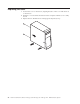
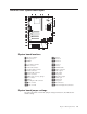
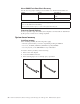
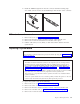
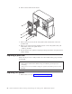
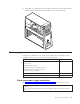
Table Of Contents
- Contents
- Chapter 1. General Checkout
- Chapter 2. General Information
- Chapter 3. Diagnostics
- Setup Utility program
- Product Recovery Program menu
- Diagnostics
- Diagnostics download
- Navigating through the diagnostic programs
- Running diagnostic tests
- Test selection
- Module test menu/hardware configuration report
- Memory Diagnostic tests
- Alert-On LAN™ test
- Asset ID™ test
- Test results
- Hard file Smart test
- Fixed Disk Optimized Test
- Quick and Full erase - hard drive
- Iomega Zip drive test
- Asset EEPROM backup
- Viewing the test log
- When to use the Low-Level Format program
- Preparing the hard disk drive for use
- Chapter 4. Installing Options
- Chapter 5. FRU Replacements
- Chapter 6. Symptom-to-FRU Index
- Chapter 7. Parts
- Chapter 8. Additional Service Information
- Chapter 9. About this manual
- Chapter 10. Related Service Information
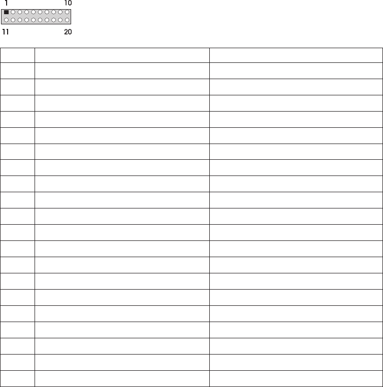
Pin Signal Function
1 3.3 V +3.3 V dc
2 3.3 V +3.3 V dc
3 COM Ground
4 5 V +5 V dc
5 COM Ground
6 5 V +5 V dc
7 COM Ground
8 POK Power Good
9 5VSB Standby Voltage
10 12 V +12 V dc
11 3.3 V +3.3 V dc
12 -12 V -12 V dc
13 COM Ground
14 PS-ON DC Remote Enable
15 COM Ground
16 COM Ground
17 COM Ground
18 No voltage Not used
19 5 V +5 V dc
20 5 V +5 V dc
If the voltages are not correct, and the power cord is good, replace the power
supply.
Power supply removal
1. Remove the power cable.
2. Remove the cover (see “Removing the cover” on page 15).
3. Remove the four screws that secure the power supply to the back of the
chassis.
34 Hardware Maintenance Manual A40 Type 6840 A40P Type 6841 A40i Type 2271: IBM NetVista Computer