IBM Hardware Maintenance Manual Types 2254, 2256, 2257, 6336, 6337, 6339, 6341, 6342, 6346, 6347, 6348
IBM Hardware Maintenance Manual Types 2254, 2256, 2257, 6336, 6337, 6339, 6341, 6342, 6346, 6347, 6348
Note: Before using this information and the product it supports, be sure to read the general information und First Edition (July 2001) The following paragraph does not apply to the United Kingdom or any country where such provisions are inconsistent with local law: INTERNATIONAL BUSINESS MACHINES CORPORATION PROVIDES THIS PUBLICATION ″AS IS″ WITHOUT ANY WARRANTY OF ANY KIND, EITHER EXPRESS OR IMPLIED, INCLUDING, BUT NOT LIMITED TO, THE LIMITED WARRANTIES OF MERCHANTABILITY OR FITNESS FOR A PARTICULAR PURPO
About this manual ® This manual contains service and reference information for the IBM computer Types 2254, 2256, 2257, 6336, 6337, 6339, 6341, 6342, 6436, 6347, 6348. This manual is divided into product service sections (by machine chassis) and a related service section, as follows: v The product service sections include procedures for isolating problems to a FRU, a Symptom-to-FRU Index, additional service information and an illustrated parts catalog.
Leia todas as instruções de cuidado e perigo antes de executar qualquer operação. Lea atentamente todas las declaraciones de precaución y peligro ante de llevar a cabo cualquier operación.
Contents About this manual . . . . . . . . . . iii Important Safety Information . . . . . . . . iii Chapter 1. General Checkout. . . . . . 1 Chapter 2. General Information . . . . . 3 Features . . . . . . . . . . . . . . Specifications . . . . . . . . . . . . Physical specification — small desktop model Physical specification — desktop model . . Physical specifications — microtower model . . . . . . . . . . . 3 5 5 6 7 Chapter 3. Diagnostics . . . . . . . . 9 Setup Utility program . . . . . . .
Chapter 8. Additional Service Information . . . . . . . . . . . . 197 Security features . . . . . . . . . . . Passwords . . . . . . . . . . . . Vital product data . . . . . . . . . . Management Information Format (MIF) . . Alert on LAN . . . . . . . . . . . BIOS levels . . . . . . . . . . . . . Flash (BIOS/VPD) update procedure . . . . Flash recovery boot block jumper. . . . . . Power management . . . . . . . . . . Automatic configuration and power interface (ACPI) BIOS. . . . . . . . . . . .
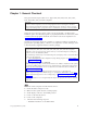
Chapter 1. General Checkout This general checkout procedure is for Types 2254, 2256, 2257, 6336, 6337, 6339, 6341, 6342, 6346, 6347, and 6348 computers. Attention: The drives in the computer you are servicing might have been rearranged or the drive startup sequence changed. Be extremely careful during write operations such as copying, saving or formatting. Data or programs can be overwritten if you select an incorrect drive.
DID YOU RECEIVE THE CORRECT RESPONSE? If NO, continue to 002 . If YES, proceed to 003 . 002 If the Power Management feature is enabled, do the following: 1. Start the Configuration/Setup Utility program (see “Setup Utility program” on page 10) 2. Select Power Management from the Configuration/Setup Utility program menu. 3. Select APM. 4. Be sure APM BIOS Mode is set to Disabled. If it is not, press Left Arrow (}) or Right Arrow (Æ) to change the setting. 5. Select Automatic Hardware Power Management. 6.
Chapter 2. General Information Features This section provides an overview of the computer features, preinstalled software, and specifications. Microprocessor Intel® Pentium™ III with 256 KB of internal L2 cache memory and MMX™ technology or an Intel Celeron™ with 256 KB of internal L2 cache memory and MMX technology Memory v Support for two dual in-line memory modules (DIMMs) v 512 KB flash memory for system programs Internal drives v 3.5-inch, 1.
v v v v v PS/2 keyboard connector Ethernet connector Monitor connector Three audio connectors (line in, line out, and microphone) Front connectors on some small desktops (S/PDIF, microphone, and headphone) v Front IEEE 1394 connector (some small desktop models) Expansion v Drive bays – Small desktop model: Three – Desktop model: Four – Microtower model: Four v 32-bit PCI expansion slots – Small desktop model: Three (expansion cards must be low profile) – Desktop model: Three – Microtower model: Three Powe
v Microsoft Windows 95 v Microsoft Windows NT® Workstation Version 4.0 v Microsoft Windows XP Personal and Professional Specifications This section lists the physical specifications for your computer. Physical specification — small desktop model Dimensions Height: 88 mm (3.4 in.) Heat output (approximate) in British thermal units (Btu) per hour: Width: 305 mm (12.0 in.) Minimum configuration: 188 Btu/hr (55 watts) Depth: 380 mm (14.9 in.
Physical specification — desktop model Dimensions Height: 140 mm (5.5 in.) Heat output (approximate) in British thermal units (Btu) per hour: Width: 425 mm (16.7 in.) Minimum configuration: 240 Btu/hr (75 watts) Depth: 425 mm (16.7 in) Maximum configuration: 940 Btu/hr (160 watts) Airflow Weight Minimum configuration as shipped: 14.0 kg (30 lb) Maximum configuration: 17.3 kg (25.
Physical specifications — microtower model Dimensions Height: 192 mm (7.6 in.) Heat output (approximate) in British thermal units (Btu) per hour: Width: 385 mm (15.2 in.) Minimum configuration: 240 Btu/hr (75 watts) Depth: 388 mm (15.3 in.) Maximum configuration: 705 Btu/hr (160 watts) Airflow Weight Minimum configuration as shipped: 9.4 kg (20 lb) Maximum configuration: 11.3 kg (25.
8 Hardware Maintenance Manual
Chapter 3. Diagnostics Setup Utility program . . . . . . . . . . . Product Recovery Program menu . . . . . . . Diagnostics . . . . . . . . . . . . . . Diagnostics program download. . . . . . . Navigating through the diagnostics programs . . Running diagnostics tests. . . . . . . . . Test selection . . . . . . . . . . . . . Module test menu/hardware configuration report Memory Diagnostic tests . . . . . . . . . Alert-On LAN™ test . . . . . . . . . . 10 11 12 12 12 12 12 13 13 14 Asset ID™ test . . . . . .
Setup Utility program Attention: A customized setup configuration (other than default settings) might exist on the computer you are servicing. Running the Setup Utility program might alter those settings. Note the current configuration settings and verify that the settings are in place when service is complete. The Setup Utility (configuration) program is stored in the permanent memory of the computer.
Product Recovery Program menu Type 2254, 2256, 2257, 6336, 6337, 6339, 6341, 6342, 6346, 6347, 6348 machines have recovery and diagnostics programs on a separate hard drive partition. The Enhanced Diagnostics diskette is not shipped with the machine or the HMM. To download the Diagnostics program, see “Diagnostics program download” on page 12.
Diagnostics The Diagnostics program uses a full range of diagnostic utilities to determine the operating condition of the computer’s hardware components. For a complete list of error codes and messages, see ″Symptom-to-FRU Index″ on page 69. Diagnostics program download To download the Diagnostics program, do the following: v Go to http://www.ibm.com/. v Select Support. v Select Desktop computing from the ″Search by Category″ pull-down menu. v Select NetVista from the ″Product Family″ list.
A selected test is marked by >>. Pressing the space bar again de-selects a test and removes the chevron. 4. Repeat steps 2 and 3 above to select all desired tests. Module test menu/hardware configuration report Depending on the diagnostics version level you are using, the installed devices in the computer are verified in one of two ways. 1. At the start of the diagnostic tests, the Module Test Menu is displayed. Normally, all installed devices in the computer are highlighted on the menu. 2.
v Memory Test-Quick The quick memory test will take about 20 seconds per MB of memory and will detect solid (stuck) memory failures only. Notes: v Either level of memory testing can be performed on all memory or a single RIMM socket. v RIMM memory requires that all memory slots be filled, either with a RIMM or a continuity module (C-RIMM). Alert-On LAN™ test The Alert On LAN test does the following: v Determines if Alert On LAN is supported on the system. v Checks the revision ID register.
Note: See “Diagnostic error codes” on page 72 for error code listings. Hard file Smart test Use the Hard File Smart Test when the system management tool has detected a hard file SMART alert. The Smart test does the following: v Interrogates IDE devices for support of the SMART instruction set. v Issues a ENABLE SMART command to make sure SMART functionality is active. v Checks the SMART RETURN STATUS command to determine if any thresholds have been exceeded.
The Full Erase Hard Drive provides a DOS utility that performs the following steps. v Performs all the steps in Quick Erase. v Provides a DOS utility that writes random data to all sectors of the hard drive. v Provide an estimate of time to completion along with a visual representation of completion status. v Provides messages that warn the user about non-recoverable process. Important: Make sure that all data is backed up before using the Quick or Full Erase functions.
When to use the Low-Level Format program Notes: 1. The low-level format is not available on all diagnostic diskettes. 2. Before formatting the hard disk drive, make a backup copy of the files on the drive to be formatted. Use the Low-Level Format program in the following situations: v When you are installing software that requires a low-level format. v When you get recurring messages from the test programs directing you to run the Low-Level Format program on the hard disk.
18 Hardware Maintenance Manual
Chapter 4. Installing Options Locating the connectors on the front of your computer . . . . . . . . . . . . . Locating the connectors on the rear of your computer . . . . . . . . . . . . . Home PNA network adapter . . . . . Removing the cover - small desktop model . . Locating components - small desktop model . Identifying parts on the system board - small desktop model . . . . . . . . . . . Installing memory - small desktop model . . Installing DIMMs . . . . . . . . .
1 Front USB connector 2 Front USB connector The following illustration shows the location of the connectors on the front of the desktop computer.
The following illustration shows the location of the connectors on the front of the microtower computer. 1 Front USB connector 2 Front USB connector Chapter 4.
Locating the connectors on the rear of your computer The following illustration shows the location of the connectors on the rear of the small desktop model computer.
The following illustration shows the location of the connectors on the rear of the desktop model computer.
The following illustration shows the location of the connectors on the back of the microtower model computer.
Connector Description Mouse connector Used to attach a mouse, trackball, or other pointing device that uses a PS/2 mouse connector. Keyboard connector Used to attach a keyboard that uses a PS/2 keyboard connector. Serial connectors Used to attach an external modem, serial printer, or other device that uses a 9-pin serial connector. Parallel connector Used to attach a parallel printer, parallel scanner, or any other device that requires a 25-pin parallel connection.
Connect each computer on a home PNA network directly to a telephone-line wall connector. If you have more computers than telephone-line wall connectors in a room, use a telephone splitter at the wall connector. Actual network transfer speeds depend on many factors, such as home wiring configuration, and are often less than the maximum possible. Some Internet service provider (ISP) accounts do not allow Internet sharing or they charge extra for it.
Locating components - small desktop model The following illustration will help you locate the various components in your computer. 1 Power supply 2 PCI slot 3 System board 4 Microprocessor and heat sink 5 DIMM 6 Hard disk drive 7 CD drive or DVD drive 8 Diskette drive Identifying parts on the system board - small desktop model The system board, also called the planar or motherboard, is the main circuit board in your computer.
See the following illustration for the location of parts on the system board.
1. Remove the cover. See “Removing the cover - small desktop model” on page 26. 2. To locate the DIMM connectors. See “Identifying parts on the system board small desktop model” on page 27. 3. Open the retaining clips. 4. Make sure the notches in the DIMM align with the tabs on the connector. Push or insert the DIMM straight down into the connector until the retaining clips close. Notches What to do next: v To work with another option, go to the appropriate section.
2. Remove the slot screw and slot cover for the appropriate expansion slot. 3. Install the adapter and insert the retaining screw. What to do next: v To work with another option, go to the appropriate section. v To complete the installation, go to “Replacing the cover and connecting the cables - small desktop model” on page 33. Installing internal drives - small desktop model This section provides information and instructions for installing and removing internal drives.
The following illustration shows the locations of the drive bays The following table describes some of the drives that you can install in each bay and their height requirements. 1 Bay 1 - Max Height: 25.4 mm (1.0 in.) 2 Bay 2 - Max Height: 41.3 mm (1.6 in.) 3 Bay 3 - Max Height: 12.7 mm (0.5 in.) 3.5-inch diskette drive (preinstalled in some models) CD-ROM drive (standard in some models) 3.5-inch hard disk drive (preinstalled) Notes: 1. Drives that are greater than 41.3 mm (1.6 in.
6. Slide the drive cage halfway into the mounting tray. 7. Each integrated drive electronics (IDE) drive requires two cables; a four-wire power cable that connects to the power supply, and a signal cable that connects to the system board. You might also have an audio cable to connect. To connect a CD drive or DVD drive to your computer, follow these steps. a. Locate the signal cable that came with your computer or with the new drive. b.
Installing a Rope Clip - small desktop model To help prevent hardware theft, you can add a 3/16 inch or 5 mm Rope Clip and cable to your computer. After you add the security cable, make sure that it does not interfere with other cables that are connected to the computer. To install a Rope Clip: 1. Remove the cover (see “Removing the cover - small desktop model” on page 26). 2. Use a tool, such as a screwdriver, to remove the two metal knockouts. 3.
2. Clear any cables that might impede the replacement of the cover. 3. Place the cover over the computer and slide it to the rear until it is fully closed. Secure the cover with the screw. 4. Reconnect the external cables and cords to the computer. 5. To update the configuration, see “Module test menu/hardware configuration report” on page 13. Removing the cover - desktop model To remove the cover: 1.
Locating components - desktop model The following illustration will help you locate the various components in your computer. 1 CD drive or DVD drive 2 USB connector 3 USB connector 4 Hard disk drive 5 Diskette drive 6 DIMMs 7 System Board 8 Microprocessor and heat sink 9 PCI slots Identifying parts on the system board - desktop model The system board, also called the planar or motherboard, is the main circuit board in your computer.
See the following illustration for the location of parts on the system board.
2. To locate the DIMM connectors. See “Identifying parts on the system board desktop model” on page 35. 3. Open the retaining clips. 4. Make sure the notches in the DIMM align with the tabs on the connector. Push or insert the DIMM straight down into the connector until the retaining clips close. Notches What to do next: v To work with another option, go to the appropriate section. v To complete the installation, go to “Replacing the cover and connecting the cables - desktop model” on page 43.
2. Remove the adapter slot cover latch and the slot cover for the appropriate expansion slot. 3. Remove the adapter from its static-protective package. 4. Install the adapter into the appropriate slot on the system board. 5. Install the adapter slot cover latch. What to do next: v To work with another option, go to the appropriate section. v To complete the installation, go to “Replacing the cover and connecting the cables - desktop model” on page 43.
Internal drives are devices that your computer uses to read and store data. You can add drives to your computer to increase storage capacity and to enable your computer to read other types of media. Some of the different drives that are available for your computer are: v Hard disk drives v Tape drives v CD drives or DVD drives v Removable media drives Internal drives are installed in bays. Within this book, the bays are referred to as bay 1, bay 2, and so on.
Notes: 1. Drives that are greater than 41.3 mm (1.6 in.) high cannot be installed. 2. Install removable media (tape or CD) drives in the accessible bay: bay 1 or 2. Installing a drive To install an internal drive, follow these steps. 1. Remove the cover. See “Removing the cover - desktop model” on page 34. 2. If your computer has a CD drive or DVD drive, you might need to remove the signal and power cables from the drive. 3.
6. Make sure the drive that you are installing is set correctly as either a master or a slave device. v If it is the first CD drive or DVD drive, set as a master device. v If it is an additional CD drive or DVD drive, set as a slave device. v If it is a hard disk drive, set as a slave device. Refer to the documentation that comes with your drive for master/slave jumper information. 7. Install the drive into the bay. Align the screw holes and insert the two screws. 8.
2. Locate the secondary IDE connector and CD-ROM audio connector on the system board. See “Identifying parts on the system board - desktop model” on page 35. 3. Connect one end of the signal cable to the drive and the other to the secondary IDE connector on the system board. To reduce electronic noise, use the connectors at the end of the cable only. 4. Your computer has extra power connectors for additional drives. Connect a power connector to the drive. 5.
5. Thread the cable through the Rope Clip and around an object that is not a part of or permanently secured to the building structure or foundation, and from which it cannot be removed; then fasten the cable ends together with a lock. What to do next: To work with another option, go to the appropriate section.
3. Position the cover over the chassis and pivot the cover down over the computer until the cover snaps into place. 4. Reconnect the external cables and cords to the computer. 5. To update the configuration, see “Module test menu/hardware configuration report” on page 13. Removing the cover - microtower model To remove the cover: 1. Shut down your operating system, remove any media (diskettes, CDs, or tapes) from the drives, and turn off all attached devices and the computer. 2.
4. Remove the thumbscrews from the rear of the computer and slide the cover toward the rear of the computer. Chapter 4.
Locating components - microtower model The following illustration will help you locate the various components in your computer. 1 Microprocessor and heat sink 2 DIMM 3 PCI adapter 4 Power supply Moving the power supply - microtower model To perform some operations inside the computer, you might need to move the power supply to access parts of the system board that are difficult to see or hard to reach. Use the following procedure to provide easier access to the system board.
2. Push the metal tab and slide the power supply unit upward. 3. Rotate the power supply outward as shown. Chapter 4.
4. Remove the power supply and carefully lay it to the side. 5. To replace the power supply, reverse these steps. Identifying parts on the system board - microtower model The system board, also called the planar or motherboard, is the main circuit board in your computer. It provides basic computer functions and supports a variety of devices that are IBM-installed or that you can install later.
See the following illustration for the location of parts on the system board.
2. You might have to remove an adapter to gain access to the DIMM slots. See “Installing adapters - microtower model”. 3. To locate the DIMM connectors. See “Identifying parts on the system board microtower model” on page 48. 4. Open the retaining clips. 5. Make sure the notches in the DIMM align with the tabs on the connector. Push or insert the DIMM straight down into the connector until the retaining clips close. Notches What to do next: v Replace any adapters that were removed.
2. Remove the adapter slot cover for the appropriate expansion slot. 3. Remove the adapter from its static-protective package. 4. Install the adapter into the appropriate slot on the system board. 5. Install the screws that secure the adapter. What to do next v To work with another option, go to the appropriate section. v To complete the installation, go to “Replacing the cover and connecting the cables - microtower model” on page 56.
When you install an internal drive, it is important to note what type and size of drive that you can install in each bay. Also, it is important to correctly connect the internal drive cables to the installed drive. Drive specifications Your computer comes with the following IBM-installed drives: v A CD drive or DVD drive in bay 1 (some models) v A 3.5-inch diskette disk drive in bay 3 v A 3.
Installing a drive To install an internal drive, follow these steps. 1. Remove the cover. See “Removing the cover - microtower model” on page 44. Note: If your computer has a CD drive or DVD drive, you might need to remove the signal and power cables from the drive. 2. Remove the bay panel from the drive bay by inserting a flat-blade screwdriver at the end and gently prying it loose. 3.
5. Install the drive into the bay. Align the screw holes, and insert the two screws. 6. Each integrated drive electronics (IDE) drive requires two cables; a four-wire power cable that connects to the power supply and a signal cable that connects to the system board. You might also have an audio cable to connect. The steps to connect an IDE drive are different depending on the type of drive you are connecting. Locate the procedure below for your drive connection.
5. If you have a CD-ROM drive audio cable, connect it to the drive and the system board. To connect an additional IDE CD drive or DVD drive 1. Locate the secondary IDE connector on the system board and the three-connector signal cable. See “Identifying parts on the system board microtower model” on page 48. 2. Connect the extra connector in the signal cable to the new CD drive or DVD drive. 3. Your computer has extra power connectors for additional drives. Connect a power connector to the drive.
which it cannot be removed; then fasten the cable ends together with a lock. 1 Rope Clip 2 Bolt holes 3 Nuts What to do next: To work with another option, go to the appropriate section. Replacing the cover and connecting the cables - microtower model After working with options, you need to install any removed parts, replace the cover, and reconnect any cables, including power cords and telephone lines.
3. Position the cover over the chassis so that the front edge is approximately one inch away from the front bezel. 4. Lower the cover down over the chassis so that the rail guides engage the rails. 5. Slide the cover forward. You might need to lift the front of the cover slightly to align it properly. 6. Insert the three thumbscrews into the holes in the cover and the chassis and tighten. 7. Reconnect the external cables and cords to the computer. 8.
58 Hardware Maintenance Manual
Chapter 5. FRU Replacements Identifying parts on the system board . . . . Replacing a System Board - Small Desktop Model Replacing a processor - Small Desktop Model . . Power supply removal - Small Desktop Model . Replacing a System Board - Desktop Model . . . 59 60 . 61 . 62 . 62 Replacing a processor - Desktop Model . . . Power supply removal - Desktop Model . . . Replacing a system board - Microtower Model Replacing a processor - Microtower Model . . Power supply removal - Microtower Model . . . . . .
See the following illustration for the location of parts on the system board.
Notes: 1. The BIOS and Vital Product Data (VPD) for the computer you are servicing must be installed on the new system board (FRU) after it is installed in the computer. To do this, you must run the Flash Update program using the Flash Update diskette. See “BIOS levels” on page 199, “Vital product data” on page 198, and “Flash (BIOS/VPD) update procedure” on page 200. 2. Always ensure the latest level of BIOS is installed on the computer.
2. Turn off the system and peripheral devices and disconnect all external cables and power cords; then, remove the cover (see “Removing the cover - small desktop model” on page 26 for details). 3. Push down on the retainer clip, and at the same time, use a flat bladed screwdriver to carefully pry the metal loop from under the hook attaching the fansink to the processor. 4. Carefully remove the other metal loop from the hook attaching the fansink to the processor. Lift up and remove the fansink.
Notes: 1. The BIOS and Vital Product Data (VPD) for the computer you are servicing must be installed on the new system board (FRU) after it is installed in the computer. To do this, you must run the Flash Update program using the Flash Update diskette. See “BIOS levels” on page 199, “Vital product data” on page 198, and “Flash (BIOS/VPD) update procedure” on page 200. 2. Always ensure the latest level of BIOS is installed on the computer.
2. Turn off the system and peripheral devices and disconnect all external cables and power cords; then, remove the cover (see “Removing the cover - desktop model” on page 34 for details). 3. Push down on the retainer clip, and at the same time, use a flat bladed screwdriver to carefully pry the metal loop from under the hook attaching the fansink to the processor. 4. Carefully remove the other metal loop from the hook attaching the fansink to the processor. Lift up and remove the fansink.
Replacing a system board - Microtower Model Important: Before replacing a system board, back up Asset information by using the “Asset EEPROM backup” on page 16. Notes: 1. The BIOS and Vital Product Data (VPD) for the computer you are servicing must be installed on the new system board (FRU) after it is installed in the computer. To do this, you must run the Flash Update program using the Flash Update diskette.
v Memory modules 6. Ensure that the new system board jumper settings match the old system board jumper settings. Replacing a processor - Microtower Model Attention: When you handle ESD-sensitive devices, take precautions to avoid damage from static electricity. For details on handling these devices, see “Handling electrostatic discharge-sensitive devices” on page 210. 1. Review the safety precautions listed in “Safety information” on page 207. 2.
4. Slide the power supply unit up toward the top of the chassis. 5. Rotate the power supply outward as shown. Chapter 5.
6. Pull the power supply forward and carefully rotate it toward the front of the chassis.
Chapter 6. Symptom-to-FRU Index SDRAM memory errors . Hard disk drive boot error Power Supply Errors . . Diagnostic error codes . . Beep symptoms . . . . . . . . . . . . . . . . . . . . . . . . . . . . . . . . . . . . . . . . . . . . . . . . . 70 70 71 72 90 No-beep symptoms . . . . POST error codes . . . . Miscellaneous error messages Undetermined problems . . . . . . . . . . . . . . . . . . . . . . . . . . . . . . . 92 . 93 . 107 .
SDRAM memory errors SDRAM error messages issued by the IBM PC Enhanced Diagnostics. Error FRU/Action 2xx Replace the SDRAM in the socket identified by the last digit of the error code. A memory error was detected in SDRAM socket Y. Re-run the test. If the same error code occurs again, replace the system board. Corrupt BIOS Reflash the BIOS. Information in BIOS is not as expected. Perform boot block recovery. Not able to find expected DMI information from BIOS. Replace the system board.
Power Supply Errors If the power-on indicator is not on, the power supply fan is not running, or the computer will not power-off, use the following procedures. Check/Verify FRU/Action Check the following for proper installation. Reseat v Power Cord v On/Off Switch connector v On/Off Switch Power Supply connector v System Board Power Supply connectors v Microprocessor(s) connection Check the power-on switch for continuity. Power Cord Check the power-on switch for continuity.
Diagnostic error codes Refer to the following diagnostic error codes when using the diagnostic tests. See ″Diagnostics″ on page 9 for the specific type for information about the Diagnostic programs. In the following index, X can represent any number. Diagnostic Error Code FRU/Action 000-000-XXX BIOS Test Passed 1. No action 000-002-XXX BIOS Timeout 1. Flash the system 000-024-XXX BIOS Addressing test failure 1. Flash the system 000-025-XXX BIOS Checksum Value error 1. Flash the system 2.
Diagnostic Error Code FRU/Action 000-197-XXX BIOS test warning 1. Make sure the component that is called out is connected and/or enabled 2. Re-run test 3. Component that is called out in warning statement 4. Component under test 000-198-XXX BIOS test aborted 1. If a component is called out, make sure it is connected and/or enabled 2. Flash the system and re-test 3. Go to the ″Undetermined problems″ section 000-199-XXX BIOS test failed, cause unknown 1. Go to the ″Undetermined problems″ section 2.
Diagnostic Error Code FRU/Action 001-038-XXX System Extension failure 1. Adapter card 001-039-XXX System DMI data structure error 1. Flash the system 001-040-XXX System IRQ failure 1. Power-off/on system and re-test 001-041-XXX System DMA failure 1. Power-off/on system and re-test 001-195-XXX System Test aborted by user 1. Information 001-196-XXX System test halt, error threshold exceeded 1. Press F3 to review the log file 001-197-XXX System test warning 1.
Diagnostic Error Code FRU/Action 001-271-XXX System IRQ4 failure 1. Device on IRQ4 001-272-XXX System IRQ5 failure 1. Device on IRQ5 001-273-XXX System IRQ6 (diskette drive) failure 1. Diskette Cable 001-274-XXX System IRQ7 failure 1. Device on IRQ7 001-275-XXX System IRQ8 failure 1. Device on IRQ8 001-276-XXX System IRQ9 failure 1. Device on IRQ9 001-277-XXX System IRQ10 failure 1. Device on IRQ10 001-278-XXX System IRQ11 failure 1. Device on IRQ11 001-279-XXX System IRQ12 failure 1.
Diagnostic Error Code FRU/Action 001-301-XXX System RTC Century byte error 1. Flash the system 005-000-XXX Video Test Passed 1. No action 005-00X-XXX Video error 1. Video card, if installed 005-010-XXX 005-011-XXX 005-012-XXX 005-013-XXX Video Signal failure 1. Video card, if installed 005-016-XXX Video Simple Pattern test failure 1. Video Ram 005-024-XXX Video Addressing test failure 1. Video card, if installed 005-025-XXX Video Checksum Value error 1.
Diagnostic Error Code FRU/Action 005-197-XXX Video test warning 1. Make sure the component that is called out is connected and/or enabled 2. Re-run test 3. Component that is called out in warning statement 4. Component under test 005-198-XXX Video test aborted 1. If a component is called out, make sure it is connected and/or enabled 2. Flash the system and re-test 3. Go to the ″Undetermined problems″ section 005-199-XXX Video test failed, cause unknown 1. Go to the ″Undetermined problems″ section 2.
Diagnostic Error Code FRU/Action 011-000-XXX Serial port Interface Test Passed 1. No action 011-001-XXX Serial port Presence 1. Remove external serial device, if present 2. Run setup, enable port 3. System board 011-002-XXX 011-003-XXX Serial port Timeout/Parity error 1. System board 011-013-XXX 011-014-XXX Serial port Control Signal/Loopback test failure 1. System board 011-015-XXX Serial port External Loopback failure 1. Wrap plug 011-027-XXX Serial port Configuration/Setup error 1.
Diagnostic Error Code FRU/Action 014-001-XXX Parallel port Presence 1. Remove external parallel device, if present 2. Run setup, enable port 3. System board 014-002-XXX 014-003-XXX Parallel port Timeout/Parity error 1. System board 014-013-XXX 014-014-XXX Parallel port Control Signal/Loopback test failure 1. System board 014-015-XXX Parallel port External Loopback failure 1. Wrap plug 014-027-XXX Parallel port Configuration/Setup error 1. Run Setup, enable port 2. System board 2.
Diagnostic Error Code FRU/Action 015-002-XXX USB port Timeout 1. Remove USB device(s) and re-test 015-015-XXX USB port External Loopback failure 1. Remove USB device(s) and re-test 015-027-XXX USB port Configuration/Setup error 1. Flash the system 015-032-XXX USB port Device Controller failure 1. System board 015-034-XXX USB port buffer allocation failure 1. Reboot the system 2. System board 2. System board 2. System board 2. Flash the system 3. Run memory test 4.
Diagnostic Error Code FRU/Action 018-195-XXX PCI Card Test aborted by user 1. PCI card 2. Information 3. Re-start the test, if necessary 018-196-XXX PCI Card test halt, error threshold exceeded 1. Press F3 to review the log file 018-197-XXX PCI Card test warning 1. Make sure the component that is called out is connected and/or enabled 2. Re-start the test to reset the log file 2. Re-run test 3. Component that is called out in warning statement 4.
Diagnostic Error Code FRU/Action 020-199-XXX PCI test failed, cause unknown 1. Go to the ″Undetermined problems″ section 2. Flash the system and re-test 3. Replace component under function test 020-262-XXX PCI system error 1. PCI card 2. Riser card, if installed 3. System board 025-000-XXX IDE interface Test Passed 1. No action 025-00X-XXX 025-01X-XXX IDE interface failure 1. IDE signal cable 2. Check power supply 3. IDE device 4.
Diagnostic Error Code FRU/Action 030-00X-XXX 030-01X-XXX SCSI interface failure 1. SCSI signal cable 2. Check power supply 3. SCSI device 4. SCSI adapter card, if installed 5. System board 030-027-XXX SCSI interface Configuration/Setup error 1. SCSI signal cable 2. Flash the system 3. SCSI device 4. SCSI adapter card, if installed 5. System board 030-03X-XXX 030-04X-XXX SCSI interface error 1. SCSI signal cable 2. Check power supply 3. SCSI device 4. SCSI adapter card, if installed 5.
Diagnostic Error Code FRU/Action 035-196-XXX RAID interface test halt, error threshold exceeded 1. Press F3 to review the log file 035-197-XXX RAID interface test warning 1. Make sure the component that is called out is connected and/or enabled 2. Re-start the test to reset the log file 2. Re-run test 3. Component that is called out in warning statement 4. Component under test 035-198-XXX RAID interface test aborted 1. If a component is called out, make sure it is connected and/or enabled 2.
Diagnostic Error Code FRU/Action 071-199-XXX Audio port test failed, cause unknown 1. Go to the ″Undetermined problems″ section 2. Flash the system and re-test 3. Replace component under function test 071-25X-XXX Audio port failure 1. Speakers 2. Audio card, if installed 3. System board 080-000-XXX Game Port interface Test Passed 1. No action 080-XXX-XXX Game Port interface Error 1. Remove the game port device and re-test the system 080-195-XXX Game Port interface Test aborted by user 1.
Diagnostic Error Code FRU/Action 086-196-XXX Mouse Port interface test halt, error threshold exceeded 1. Press F3 to review the log file 086-197-XXX Mouse Port interface test warning 1. Make sure the component that is called out is connected and/or enabled 2. Re-start the test to reset the log file 2. Re-run test 3. Component that is called out in warning statement 4. Component under test 086-198-XXX Mouse Port interface test aborted 1.
Diagnostic Error Code FRU/Action 170-195-XXX Voltage Sensor(s) Test aborted by user 1. Information 170-196-XXX Voltage Sensor(s) test halt, error threshold exceeded 1. Press F3 to review the log file 170-197-XXX Voltage Sensor(s) test warning 1. Make sure the component that is called out is connected and/or enabled 2. Re-start the test, if necessary 2. Re-start the test to reset the log file 2. Re-run test 3. Component that is called out in warning statement 4.
Diagnostic Error Code FRU/Action 175-199-XXX Thermal Sensor(s) test failed, cause unknown 1. Go to the ″Undetermined problems″ section 2. Flash the system and re-test 3. Replace component under function test 175-250-XXX 175-251-XXX Thermal Sensor(s) limit error 1. Check fans 2. Check Power supply 3. Microprocessor 4. System board 185-000-XXX Asset Security Test Passed 1. No action 185-XXX-XXX Asset Security failure 1. Flash system 185-278-XXX Asset Security Chassis Intrusion 1.
Diagnostic Error Code FRU/Action 217-28X-XXX 217-29X-XXX Hard Disk Drive (SCSI) error 1. Hard Disk Drive Cable 2. Check power supply voltages 3. Hard Disk drive (SCSI) 4. SCSI adapter card 5. System board 220-000-XXX Hi-Capacity Cartridge Drive Test Passed 1. No action 220-XXX-XXX Hi-Capacity Cartridge Drive error 1. Remove the Hi-Capacity Cartridge Drive and re-test the system 301-XXX-XXX Keyboard error 1. Keyboard 2. Check and test mouse 3. System board 301-000-XXX Keyboard Test Passed 1.
Beep symptoms Beep symptoms are short tones or a series of short tones separated by pauses (intervals without sound). See the following examples. Beeps Description 1-2-X v One beep v A pause (or break) v Two beeps v A pause (or break) v Any number of breaks 4 Four continuous beeps Use the following table to diagnose beep symptoms. Beep Symptom FRU/Action 1-1-3 CMOS read-write error 1. Run Setup 1-1-4 ROM BIOS check error 1. System Board 1-2-X DMA error 1. System Board 1-3-X 1.
Beep Symptom FRU/Action 3-2-4 Keyboard controller failed 1. System Board 3-3-4 Screen initialization failed 1. Video Adapter (if installed) 3-4-1 Screen retrace test detected an error 1. Video Adapter (if installed) 2. Keyboard 2. System Board Display 2. System Board 3. Display 3-4-2 POST is searching for video ROM 1. Video Adapter (if installed) 4 1. Video Adapter (if installed) 2. System Board 2. System Board All other beep code sequences 1.
No-beep symptoms Important: Type 2254, 2256, 2257, 6336, 6337, 6339, 6341, 6342, 6346, 6347, and 6348 computers default to come up quiet (no beep and no memory count and checkpoint code display) when no errors are detected by POST. To enable beep and memory count and checkpoint code display when a successful POST occurs, do the following: 1. Select Start Options in the Configuration/Setup Utility program (see “Setup Utility program” on page 10). 2. Set Power-On Self-Test to Enhanced.
POST error codes Each time you power-on the system, it performs a series of tests that check the operation of the system and some options. This series of tests is called the Power-On Self-Test, or POST. POST does the following operations.
POST Error Code FRU/Action 111 I/O channel parity error 1. Reseat adapters 2. Any adapter 3. Riser card 4. System Board 114 Adapter ROM error 1. Adapter Memory 2. System Board 3. Riser card 129 Internal cache test error 1. Processor 2. L2 Cache Memory 3. System Board 151 Real-time clock failure 1. System Board 161 Bad CMOS battery 1. Run Setup 2. CMOS Backup Battery (see “Safety information” on page 207) 3. System Board 162 Configuration mismatch 1. Run Setup and verify Configuration 2.
POST Error Code FRU/Action 167 Microprocessor installed that is not supported by the current POST/BIOS 1. Run Setup. Check Stepping level for the BIOS level needed, then perform the flash update. 2. Processor 168 Alert on LAN error 1. Run Setup. Check to see that Ethernet and Alert on LAN are enabled. 2. System Board 3. Riser card 17X, 18X 1. C2 Security 175 1. Run Configuration. See “Setup Utility program” on page 10. 2. System Board 176 1.
POST Error Code FRU/Action 262 POST detected a base memory or extended memory type error 1. Run Setup. Check System Summary menu for memory. (See “Setup Utility program” on page 10.) 2. Run the Extended Memory Diagnostic tests. 301 1. Keyboard 2. Keyboard Cable 3. System Board 303 With an 8603 error 1. Mouse 2. Keyboard 3. Keyboard Cable 4. System Board 303 With no 8603 error 1. Keyboard 2. Keyboard Cable 3. System Board 3XX Not listed above 1. Keyboard 2. Keyboard Cable 3. System Board 5XX 1.
POST Error Code FRU/Action 6XX Not listed above 1. Diskette Drive 2. System Board 3. Riser card 4. External Drive Adapter 5. Diskette Drive Cable 6. Power Supply 762 Math coprocessor configuration error 1. Run Setup 2. Processor 3. System Board 7XX Not listed above 1. Processor 962 Parallel port configuration error 1. Run Configuration 2. System Board 2. Parallel Adapter (if installed) 3. System Board 9XX 1. Printer 2. System Board 1047 1.
POST Error Code FRU/Action 1117 Failed baud rate test 1. Run Enhanced Diagnostics 1162 Serial port configuration error 1. Run Configuration 2. Serial Adapter (if installed) 3. System Board 11XX Not listed above 1. System Board 1201 1. System Board 2. Any Serial Device 1202, 1206, 1208, 1209, 12XX 1. Dual Async Adapter/A 2. System Board 3. Any Serial Device 1207 1. Communications Cable 2. Dual Async Adapter/A 13XX 1.
POST Error Code FRU/Action 180X, 188X PCI configuration or resource error 1. Run Setup and verify PCI/ISA configuration settings. 2. If necessary, set ISA adapters to Not available to allow PCI adapters to properly configure. 3. Remove any suspect ISA adapters. 4. Rerun diagnostics. 5. PCI Adapter 1962 Boot sequence error 1. Possible hard disk drive problem; see “Hard disk drive boot error” on page 70. 209X 1. Diskette Drive 2. Diskette Cable 20XX Not listed above 1. BSC Adapter 21XX 1.
POST Error Code FRU/Action 5962 An IDE device (other than hard drive) configuration error 1. Run Configuration 2. CD-ROM Drive 3. CD-ROM Adapter 4. Zip or other ATAPI device 5. System Board 6. Riser card 62XX 1. 1st Store Loop Adapter 2. Adapter Cable 63XX 1. 2nd Store Loop Adapter 2. Adapter Cable 64XX 1. Network Adapter 71XX 1. Voice Adapter 74XX 1. Video Adapter (if installed) 76XX 1. Page Printer Adapter 78XX 1. High Speed Adapter 79XX 1. 3117 Adapter 80XX 1.
POST Error Code FRU/Action 10103, 10110, 101171 1. System Board 2. Data/Fax Modem 3. Riser card 10117 Not listed above 1. Check system speaker 2. Check PSTN cable 3. External DAA (if installed) 4. Modem 10118 1. Run Diagnostics and verify the correct operation of the modem slot 2. Modem 10119 1. Diagnostics detected a non-IBM modem 2. Modem 10120 1. Check PSTN Cable 2. External DAA (if installed) 3.
POST Error Code FRU/Action 10461 Drive format error 1. Run Enhanced Diagnostics 10462 Controller seek error 1. Run Enhanced Diagnostics 10464 Hard Drive read error 1. Run Enhanced Diagnostics 10467 Drive non-fatal seek error 1. Run Enhanced Diagnostics 10468 Drive fatal seek error 1. Run Enhanced Diagnostics 10469 Drive soft error count exceeded 1. Run Enhanced Diagnostics 10470, 10471, 10472 Controller wrap error 1. Run Enhanced Diagnostics 10473 Corrupt data.
POST Error Code FRU/Action 119XX 1. 3119 Adapter 121XX 1. Modem Adapter 2. Any Serial Device 3. System Board 4. Riser card 136XX 1. ISDN Primary Rate Adapter 2. System Board 3. Riser card 137XX 1. System Board 141XX 1. Realtime Interface Coprocessor Portmaster Adapter/A 143XX 1. Japanese Display Adapter 2. System Board 3. Riser card 14710, 14711 1. System Board Video Adapter 2. Adapter Video Memory 148XX 1. Video Adapter 14901, 14902, 1491X, 14922 1. Video Adapter (if installed) 2.
POST Error Code FRU/Action 185XXXX 1. DBCS Japanese Display Adapter/A 2. System Board 3. Riser card 20001 to 20003 1. Image Adapter/A Image-I Adapter/A 2. Memory Module DRAM, VRAM 20004 1. Memory Module DRAM, VRAM 2. Image Adapter/A Image-I Adapter/A 20005 to 20010 1. Image Adapter/A Image-I Adapter/A 2. Memory Module DRAM, VRAM 200XX Not listed above 1. Image Adapter/A 2. Image-I Adapter/A 3. Memory Module DRAM, VRAM 4. System Board 5. Riser card 20101 to 20103 1. Printer/Scanner Option 2.
POST Error Code FRU/Action Tape Drive green ″in use″ LED fails to come on 1. Tape Drive 2. SCSI Adapter or System Board 3. SCSI Cable (internal) 4. SCSI Cable (external) Tape automatically ejected from drive 1. Tape Cassette Drive SCSI ID on rotary switch does not match SCSI ID set in configuration. Verify drive switches inside cover are set to zero 1. Rotary Switch Circuit Board Tape sticks or breaks in drive. Verify that the tapes used meet ANSI standard X3B5 1. Tape Cassette 212XX 1.
POST Error Code FRU/Action 27512 1. WMSELF.DGS diagnostics file is missing 2. WMSELF.DGS diagnostics file is incorrect 27535 1. 3V Lithium Backup Battery 2. ServerGuard Adapter 27554 1. Internal Temperature out of range 2. ServerGuard Adapter 27555, 27556 1. ServerGuard Adapter 2. Power Supply 27557 1. 7.2V NiCad Main Battery Pack 2. ServerGuard Adapter 27558, 27559, 27560, 27561 1. PCMCIA Type II Modem 2. ServerGuard Adapter 27562 1. External Power Control not connected 2.
Miscellaneous error messages Message/Symptom FRU/Action CMOS Backup Battery inaccurate 1. CMOS Backup Battery (see “Safety information” on page 207) 2. System Board Changing colors 1. Display Computer will not power-off. See “Power Supply Errors” on page 71. 1. Power Switch 2. System Board 3. Riser card Computer will not RPL from server 1. Ensure that network is in startup sequence as first device or first device after diskette 2. Ensure that network adapter is enabled for RPL 3.
Message/Symptom ″Insert a Diskette″ icon appears with a known-good diagnostics diskette in the first 3.5-inch diskette drive. FRU/Action 1. System Board 2. Diskette Drive Cable 3. Riser card 4. Network Adapter Intensity or color varies from left to right of characters and color bars 1. Display No power or fan not running 1. See “Power Supply Errors” on page 71. Non-system disk or disk error-type message with a known-good diagnostic diskette. 1. Diskette Drive 2. System Board 2. System Board 3.
Message/Symptom FRU/Action Some or all keys on the keyboard do not work 1. Keyboard 2. Keyboard Cable 3. System Board Undetermined problems Check the power supply voltages (see “Power Supply Errors” on page 71). If the voltages are correct, return here and continue with the following steps. 1. Power-off the computer. 2. Remove or disconnect the following components (if installed) one at a time. a. Non-IBM devices b. External devices (modem, printer, or mouse) c. Any adapters d. Riser card e.
110 Hardware Maintenance Manual
Chapter 7. Parts Small Desktop Model Types 2256, 6339, 6346 © Copyright IBM Corp.
1 2 3 4 10 5 6 9 8 7 Machine Type 2256 1 112 Hardware Maintenance Manual Top Cover Assembly, Black (models 22T 23V 52T 53V 81V 93V 1FA 2AA 95A 12Q 22Q 23M B3M 51Q 52Q 54M 71Q 82M 92M 91Q,72J 73J 74J 75J 94J 76J 77J 78J 83J 84J 1AJ 1BJ 1CJ 1DJ 2BJ 23C 95A) 31P5610
Machine Type 2256 1 Top Cover Assembly, Black (models 96J 97J 98J 99J) 58P9863 2 Intel Celeron 100/800 128K (model 12Q) 24P5784 2 Intel Celeron 100/850 128K (models 22Q, 22T, 23C, 23M, 23V) 24P5944 2 Intel Celeron 900 MHz (model 54M) 32P4094 2 Intel Celeron 950 MHz (models 51Q 52-QT 71Q 72J 73J 74J 75J 76J 77J 78J) 48P5039 2 Intel Celeron 1 GHz (models 53V 81V 82M) 48P5040 2 Intel Celeron 1.1 GHz (models 91Q 92M 93V 94J) 33P0813 2 Intel Celeron 1.
Machine Type 2256 114 9 Basic Chassis, Black (all models) 31P5611 10 120 W Power Supply, PFC version (all models) 25P4966 Front panel assembly (models 84J 1AJ 1BJ 1CJ 1DJ 1FA 2AA) 32P4158 Front panel (models 83J 2BJ) 32P4159 Cable, flat (10-pin) (models 83J 84J 1AJ 1BJ 1CJ 1DJ 1FA 2AA 2BJ) 32P4156 Cable, 5-pin (models 83J 84J 1AJ 1BJ 1CJ 1DJ 1FA 2AA 2BJ) 32P4165 INTEL Lake Clark 2.
Machine Type 2256 System Stand, Black (all models) 32P4065 I/O Slot Cover (all models) 31P5615 Cable - Primary IDE (all models) 31P5616 FDD Cable (all models) 31P5617 Cable - Secondary IDE (CD_ROM) (all models) 31P5618 CD-ROM Audio Cable (all models) 75H9219 Shields 5.
Recovery CDs Win ME - Machine Type 2256 Slovenian 25P5979 Slovak 25P5980 Greek 25P5981 Turkish 25P5982 Thai (model 22T 52T) 25P5983 Recovery CDs Win 2K - Machine Type 2256 116 Hardware Maintenance Manual US English Win 2K (models 27U, B5U, B7U) 25P6019 UK English Win 2K (models PCG, 19G, 26G, B5G, 32G, 42G, 51G) 25P6020 AP English Win 2K (models 1AA, 1BQ, 27A, 27D, 28Q, A2A, B7A, PCQ) 25P6021 French Win 2K (models PCG, 19G, 26G, B5G, 32G, 42G, 51G) 25P6022 Canadian French Win 2K (models
Recovery CDs Win 98 SE - Machine Type 2256 US English (models 23U, B4U, 20U) 25P6102 UK English (models 22G, B6G, PAG, PBG, 13G 31G, 41G, 52G) 25P6103 AP English (models 13D, 18A, 21D, 23A, 25Q, A1A, B3A, B8D, 13A) 25P5715 French (models 22G, B6G, PAG, PBG, 13G 31G, 41G, 52G) 25P6105 Canadian French (models 23F, B4F) 25P6106 Spanish (models 22G, B6G, PAG, PBG, 13G 31G, 41G, 52G) 25P6107 LA Spanish (models 14S, 25S, B2S) 25P6108 Portuguese (models 22G, B6G, PAG, PBG) 25P6109 Brazil, Portugues
Recovery CDs Win XP Home - Machine Type 2256 Brazil/Portuguese 33P2100 Swedish 33P2103 Danish 33P2106 Finnish 33P2109 Norwegian 33P2112 Dutch 33P2115 Hebrew Enabled 33P2118 Polish 33P2121 Russian 33P2124 Czech 33P2127 Arabic Enabled 33P2130 Turkish 33P2133 Hungarian 33P2136 Greek 33P2139 Portuguese 33P2142 Japan (Direct) 46P4762 Japan (OCN) (models 73J 76J 1CJ 1DJ) 46P4767 Japan (models 77J 78J 83J 84J 1AJ 1BJ 2BJ 96J 97J 98J 99J) 62P7754 Keyboards - Machine Type 2256 11
Keyboards - Machine Type 2256 Japanese, Rapid Access IIIe Keyboard (black) (models 72J 73J 74J 75J 94J 76J 77J 78J 83J 84J 1AJ 1BJ 1CJ 1DJ 2BJ 96J 97J 98J 99J) 19K1928 LA Spanish, Rapid Access IIIe Keyboard (black) 19K1930 Norwegian, Rapid Access IIIe Keyboard (black) 19K1931 Polish, Rapid Access IIIe Keyboard (black) 19K1932 Portuguese, Rapid Access IIIe Keyboard (black) 19K1933 Romanian, Rapid Access IIIe Keyboard (black) 19K1934 Russian, Rapid Access IIIe Keyboard (black) 19K1935 Russian/Cy
Power Cords - Machine Type 2256 Polish 1339520 Portuguese 1339520 Serbian 1339520 Slovakian 1339520 South African 14F0015 Spanish 1339520 Swiss 1339520 Swiss - French/German 14F0051 US English (models 22T 23V 52T 53V 81V 93V 1FA 2AA 95A) 93F2364 UK - Ireland (models 12Q 22Q 23M B3M 51Q 52Q 54M 71Q 82M 92M 91Q) 14F0033 Yugoslavian 1339520 Chile 14F0069 Argentina, Paraguay, & Uruaguay 36L8880 Japan (models 72J 73J 74J 75J 94J 76J 77J 78J 83J 84J 1AJ 1BJ 1CJ 1DJ 2BJ 96J 97J 98J 99J)
Machine Type 6339 2 Intel Celeron 1.2 GHz (model 20J) 57P7000 2 Intel Celeron 1.
Machine Type 6339 122 6 CD-ROM 48x, Lite-On, Black (models 21U 21F 24U 24F 24G B5U B5F B8U B3U B3F B8G 26U 26G B7U B7F C2G 41U 41F 41A 41T 41Q 41J 44U 44F 44A 46J 49G 48U 48F 48J B6U B6F B6J 51S 51P 52S 52P 54U 54F 56-UFG 57U 57G 64-UFG 65G 66U 66F 67-SP 68-SP 55A 55F 55U 81U 71G 72G 72A 2AJ 2BJ 2CJ 2DJ 2EJ 2FA 3AA 1AA 1BJ 1CJ 1DJ 1EJ 1FJ) 19K1531 6 CD-ROM 48x, Samsung (models 21U 21F 24U 24F 24G B5U B5F B8U B3U B3F B8G 26U 26G B7U B7F C2G 41U 41F 41A 41T 41Q 41J 44U 44F 44A 46J 49G 48U 48F 48J B6U B6
Machine Type 6339 Fansink - Heatsink with Fan and Clip Assembly (models 81U 71G 72G 72A 73A 82J 83J 84J 1AA 1BJ 1CJ 1DJ 1EJ 1FJ 10J) 32P4086 Fansink - Heatsink with Fan and Clip Assembly (models 2AJ 2BJ 2CJ 2DJ 2EJ 2FA 3AA 20J) 22P4368 20 GB Hardfile EIDE 5400rpm (PAJ PBJ 11A 14A 21U 21F 21A 24U 24F 24G 24A 24T 24Q 24J 26U 27J B6J B7J B8J B8G C1T C1Q 16U 26G B7U B7F C2G 41U 41F 41G 41A 41T 41Q 41J 44U 44F 44A 45J 46J 49G 48U 48F 48J B6U B6F 46G 48U 48F 53J 56U 56F 56G 56ATQJ 57UG 63J 63U 63F 64U 64F 64G
Machine Type 6339 FDD Cable (all models) 31P5617 Cable - Secondary IDE (CD_ROM) (all models) 31P5618 CD-ROM Audio Cable (all models) 75H9219 Shields 5.
Recovery CDs Win 2K - Machine Type 6339 Czech Win 2K (models 24G B8G 26G C2G 49G 41G 56G 57G 64G 65G 72G) 25P6036 Russian Win 2K (models 24G B8G 26G C2G 49G 41G 56G 57G 64G 65G 72G) 25P6037 Polish Win 2K (models 24G B8G 26G C2G 49G 41G 56G 57G 64G 65G 72G) 25P6038 Hungarian Win 2K (models 24G B8G 26G C2G 49G 41G 56G 57G 64G 65G 72G) 25P6039 Turkish Win 2K (models 24G B8G 26G C2G 49G 41G 56G 57G 64G 65G 72G) 25P6040 Thai Win 2K (models 24T 41T 56T 64T) 25P6041 Japan Win 2K (models 24J 41J B6J 56J
Recovery CDs Win 98 SE - Machine Type 6339 Greek (model 44G 71G) 25P6126 Turkish (model 44G 71G) 25P6127 Thai (model C1T 41T) 25P6104 Recovery CDs Win XP Home - Machine Type 6339 English (models 81U 73A) 33P2085 French 33P2088 German 33P2091 Italian 33P2094 Spanish 33P2097 Brazil, Portuguese 33P2100 Swedish 33P2103 Danish 33P2106 Finnish 33P2109 Norwegian 33P2112 Dutch 33P2115 Hebrew Enabled 33P2118 Polish 33P2121 Russian 33P2124 Czech 33P2127 Arabic Enabled 33P2130 Tur
Keyboards, Netvista PS2 - Machine Type 6339 Danish, white (all models) 32P5047 Dutch, white (all models) 32P5048 French, white (all models) 32P5049 French Canadian, white (all models) 32P5050 French Canadian, white (all models) 32P5051 German, white (all models) 32P5052 Greek, white (all models) 32P5053 Hebrew, white (all models) 32P5054 Hungarian, white (all models) 32P5055 Iceland, white (all models) 32P5056 Italy, white (all models) 32P5057 Japanese, white (all models) 32P5058 Kor
Keyboards, Netvista PS2 - Machine Type 6339 Danish, Black (all models) 32P5007 Dutch, Black (all models) 32P5008 French, Black (all models) 32P5009 French Canadian, Black (all models) 32P5010 French Canadian, Black (all models) 32P5011 German, Black (all models) 32P5012 Greek, Black (all models) 32P5013 Hebrew, Black (all models) 32P5014 Hungarian, Black (all models) 32P5015 Iceland, Black (all models) 32P5016 Italy, Black (all models) 32P5017 Japanese, Black (all models) 32P5018 Kor
Keyboards, PC Next Lite - Machine Type 6339 Czech, Black 37L2559 Danish, Black 37L2560 Dutch, Black 37L2561 French, Black 37L2562 German, Black 37L2563 Greek, Black 37L2564 Hebrew, Black 37L2565 Hungarian, Black 37L2566 Iceland, Black 37L2567 Italy, Black 37L2568 Norwegian, Black 37L2569 Polish, Black 37L2570 Brazil/Portuguese, Black 37L2554 Portuguese, Black 37L2571 Romanian, Black 37L2572 Russian, Black 37L2573 Serbian/Cyrillic, Black 37L2574 Slovak, Black 37L2575 Spani
Keyboards, PC Next Lite - Machine Type 6339 Danish, White 37L2523 Dutch, White 37L2524 French, White 37L2525 German, White 37L2526 Greek, White 37L2527 Hebrew, White 37L2528 Hungarian, White 37L2529 Iceland, White 37L2530 Italy, White 37L2531 Norwegian, White 37L2532 Polish, White 37L2533 Brazil/Portuguese, White 37L2517 Portuguese, White 37L2534 Romanian, White 37L2535 Russian, White 37L2536 Serbian/Cyrillic, White 37L2537 Slovak, White 37L2538 Spanish, White 37L2539 Swe
Power Cords - Type 6339 Hungarian (all models) 1339520 Israel (all models) 14F0087 Italian (all models) 14F0069 Latin American (all models) 6952301 Netherlands (all models) 1339520 New Zealand (all models) 93F2365 Norwegian (all models) 1339520 Polish (all models) 1339520 Portuguese (all models) 1339520 Serbian (all models) 1339520 Slovakian (all models) 1339520 South African (all models) 14F0015 Spanish (all models) 1339520 Swiss (all models) 1339520 Swiss - French/German (all m
Machine Type 6346 132 7 3.5″ 1.44MB Diskette Drive, Black Bezel (models 12Q, 22Q, 22T, 23C, 23M, 23V, B3M) 76H4091 8 3.
Recovery CDs Win 2K - Machine Type 6346 US English Win 2K (model 24U) 25P6019 UK English Win 2K (model 24G) 25P6020 AP English Win 2K (models 24A, 24Q) 25P6021 French Win 2K (model 24G) 25P6022 Canadian French Win 2K (model 24F) 25P6023 Spanish Win 2K (model 24G ) 25P6024 LA Spanish Win 2K (model 24S) 25P6025 Brazil, Portuguese Win 2K (model 24P) 25P6026 German Win 2K (model 24G) 25P6027 Greek (model 24G) 25P6072 Hebrew (model 24G) 25P6061 Italian Win 2K (model 24G) 25P6028 Dutch Win
Recovery CDs Win 98 SE - Machine Type 6346 Finnish 25P6115 Norwegian 25P6129 Swedish 25P6116 Arabic Enabled 25P6117 Hebrew 25P6119 Czech 25P6120 Russian 25P6121 Polish 25P6122 Hungarian 25P6123 Slovenian 25P6124 Slovak 25P6125 Greek 25P6126 Turkish 25P6127 Thai 25P6104 Keyboards - Machine Type 6346 134 Hardware Maintenance Manual US English, white (models 24A, 24Q) 32P5040 Arabic, white 32P5041 Belgium/French, white 32P5042 Belgium/UK, white 32P5043 Bulgarian, white 3
Keyboards - Machine Type 6346 Romanian, white 32P5064 Russian, white 32P5065 Russian/Cy, white 32P5066 Serbian/Cyrillic, white 32P5067 Slovak, white 32P5068 Spanish, white 32P5069 Swedish/Finn, white 32P5070 Swiss F/G, white 32P5071 Thailand, white (models 24T) 32P5072 Turkish, white 32P5073 Turkish, white 32P5074 UK English, white 32P5075 US International, white 32P5076 Yugoslav/Latin, white 32P5077 Brazil/Portuguese, white 32P5078 Keyboards - Machine Type 6346 US English, Bla
Keyboards - Machine Type 6346 Romanian, Black (model 24G) 32P5024 Russian, Black (model 24G) 32P5025 Russian/Cy, Black (model 24G) 32P5026 Serbian/Cyrillic, Black (model 24G) 32P5027 Slovak, Black (model 24G) 32P508 Spanish, Black (model 24G) 32P5029 Swedish/Finn, Black (model 24G) 32P5030 Swiss F/G, Black (model 24G) 32P5031 Thailand, Black 32P5032 Turkish, Black (model 24G) 32P5033 Turkish, Black (model 24G) 32P5034 UK English, Black (model 24G) 32P5035 US International, Black 32P
Power Cords - Type 6346 Swiss - French/German (all models) 14F0051 US English (all models) 93F2364 UK - Ireland (all models) 14F0033 Yugoslavian (all models) 1339520 Chile (all models) 14F0069 Argentina, Paraguay, & Uruaguay (all models) 36L8880 Japan (all models) 24G0222 Desktop Model Types 6347, 6341, 6336 Machine Type 6347 1 Top Cover Assembly, Pearl White (all models) 06P2732 2 Intel Celeron 100/850 128K (all models) 24P5944 2 Intel PIII 933 MHz Processor 25P0719 2 Intel PIII 1G
Machine Type 6347 DASD Soft Mount HDD Rail Assembly (all models) 19K5331 Lithium Battery (all models) 33F8354 2 Button Mouse (all models) 10L6145 3.5 DASD Bracket Handle (all models) 09N5748 5.25 DASD Bracket Handle (all models) 09N5747 Blank Bezel 5.25″ Bay Kit, White (all models) 09N5732 Nameplate, Blue (all models) 09N5733 Misc.
Recovery CDs Win 98 SE - Machine Type 6347 US English 25P6102 UK English 25P6103 AP English 25P5715 French 25P6105 Canadian French 25P6106 Spanish 25P6107 LA Spanish 25P6108 Portuguese 25P6109 Brazil, Portuguese 25P6110 German 25P6111 Italian 25P6112 Dutch 25P6113 Danish 25P6114 Finnish 25P6115 Norwegian 25P6129 Swedish 25P6116 Arabic Enabled 25P6117 Hebrew 25P6119 Czech 25P6120 Russian 25P6121 Polish 25P6122 Hungarian 25P6123 Slovenian 25P6124 Slovak 25P6125
Keyboards - Machine Type 6347 German, white (all models) 32P5052 Greek, white (all models) 32P5053 Hebrew, white (all models) 32P5054 Hungarian, white (all models) 32P5055 Iceland, white (all models) 32P5056 Italy, white (all models) 32P5057 Japanese, white (all models) 32P5058 Korean, white (all models) 32P5059 LA Spanish, white (all models) 32P5060 Norwegian, white (all models) 32P5061 Polish, white (all models) 32P5062 Portuguese, white (all models) 32P5063 Romanian, white (all mo
Power Cords - Type 6347 Italian (all models) 14F0069 Latin American (all models) 6952301 Netherlands (all models) 1339520 New Zealand (all models) 93F2365 Norwegian (all models) 1339520 Polish (all models) 1339520 Portuguese (all models) 1339520 Serbian (all models) 1339520 Slovakian (all models) 1339520 South African (all models) 14F0015 Spanish (all models) 1339520 Swiss (all models) 1339520 Swiss - French/German (all models) 14F0051 US English (all models) 93F2364 UK - Ireland
Machine Type 6341 142 3 CD-ROM 48x Samsung, White (models 18A 1AA 23U 23F 23A 27U 27F 27S 27P 27A 27C 27M 27D A1A A2A B3A B4U B4F B5U B5F B5G B6G B7U B7A PAG PBG PCG PCT PCQ B7F 51G 52G 41U 41F 41S 41P 41A 41C 41M 41D 41V 44U 44F 44A 44T 44Q 45T 45Q 58U 58S 58F 58P 58A 58C 58M 58D 58W 58V 5AA 5AT 5AQ 5BT 5BQ 64U 64S 64F 64P 64G 64A 64C 64M 64D 64V 65U 65F 65G 65A 65T 65Q 66T 66Q PDT PDQ PEG PGT PGQ PHG 3CG 3DG 5AU 5AF 93C 93D 93M 93V 35G 36G 58G 5AG 71G 72G 73G 74G 75G 76G 77G 78G 7BG 7CG) 33P3209 3 C
Machine Type 6341 7 DASD Soft Mount HDD Rail Assembly (all models) 19K5331 8 3.5 DASD Bracket (all models) 06P2734 9 Chassis Assembly (all models) 06P2731 10 Fan/Speaker Bracket (all models) 09N5763 11 System Board W/O Mem/Proc (all models) xxxxxxx Important: These models may contain systemboard part number 49P0404 or 33P0825. Only install the same systemboard part number as the one you removed.
Machine Type 6341 144 14 64MB SDRAM Memory (models 12S 12P 13C 13M 13D 14S 14P18A 21C 21M 21D 23U 23F 23A 24P 24S 25S 25P 25T 25Q A1A B1S B1P B2S B2P B3A B4U B4F B8C B8M B8D 13G 13A 13T 31G 42S 42P 42C 42M 42D 42V 43S 43P 51G 51A 51T 51Q 53S 53P 54S 54P 54T 54Q 54V 61S 61P 62S 62P 62C 62M 62D 62V 39G 54C 54D 54M 54V 91C 91D 91M 91P 91S 91V 92P 92S 19G 1AA 1BQ 1BT 22G 26G 27U 27F 27S 27P 27A 27C 27M 27D 28T 28Q B5U B5F B5G B6G B7A PAG PBG PCG A2A B7U PCT PCQ B7F 20U 32G 41G 42G 51G 52G 41-UFSPACMDV 44-UFA
Machine Type 6341 Fansink - Heatsink with Fan and Clip Assembly (models B1S B1P B2S B2P B3A B4U B4F B5U B5F B5G B6G B7U B7A PCU PCG A1A A2A PCT PCQ B7F B8C B8M B8D 51G 52G 41-UFSPACMDV 42-SPCMDV 43-SP 44-UFATQ 45-TQ 46G 47G 51-GATQ 53-SP 54-SPTQV 56G 57-GTQ 58-USFPACMDWV 59-TQ 5A-ATQ 5B-TQ 61-SP 62-SPCMDV 64-USFPGACMDV 65-UFGATQ 66-TQ PBG PDT PDQ PEG PG-TQ PHG 37G 38G 39G 3AG 3BG 3CG 3DG 5AU 5AF 54C 54D 54M 54V 91C 91D 91M 91P 91S 91V 92P 92S 93C 93D 93M 93V,35G,36G,58G,5AG 71G 72G 73G 74G) 06P2458 Fansin
Recovery CDs Win 2K - Machine Type 6341 146 Hardware Maintenance Manual French Win 2K (models PCG 19G 26G B5G 32G 42G 51G 47G 57G 64G PEG 38G 3AG 3DG 35G 58G 72G 74G,76G 79G 7BG 7DG 7EG) 25P6022 Canadian French Win 2K (models 27F B5F B7F 41F 58F 64F) 25P6023 Spanish Win 2K (models PCG 19G 26G B5G 32G 42G 51G 47G 57G 64G PEG 38G 3AG 3DG 35G 58G 72G 74G,76G 79G 7BG 7DG 7EG) 25P6024 LA Spanish Win 2K (models 12S 24S 27S B1S 41S 43S 53S 58S 61S 64S 92S 83S D3S E1S E2S E3S) 25P6025 Brazil, Portuguese
Recovery CDs Win 2K - Machine Type 6341 Hungarian Win 2K (models PCG 19G 26G B5G 32G 42G 51G 47G 57G 64G PEG 38G 3AG 3DG 35G 58G 72G 74G,76G 79G 7BG 7DG 7EG) 25P6039 Turkish Win 2K (models PCG 19G 26G B5G 32G 42G 51G 47G 57G 64G PEG 38G 3AG 3DG 35G 58G 72G 74G,76G 79G 7BG 7DG 7EG) 25P6040 Thai Win 2K (model 1BT 28T PCT 45T 57T 59T 5BT 66T PDT PGT) 25P6041 Recovery CDs Win 98 SE - Machine Type 6341 US English (models 23U B4U 20U 44U 65U 5AU) 25P6102 UK English (models 22G B6G PAG PBG 13G 31G 41G 52G
Recovery CDs Win 98 SE - Machine Type 6341 Arabic Enabled (models 22G B6G PAG PBG 13G 31G 41G 52G 46G 51G 56G 65G PHG 37G 39G 3BG 3CG 36G 5AG 71G 73G 75G) 25P6117 Hebrew (models 22G B6G PAG PBG 13G 31G 41G 52G 46G 51G 56G 65G PHG 37G 39G 3BG 3CG 36G 5AG 71G 73G 75G) 25P6119 Czech (models 22G B6G PAG PBG 13G 31G 41G 52G 46G 51G 56G 65G PHG 37G 39G 3BG 3CG 36G 5AG 71G 73G 75G) 25P6120 Russian (models 22G B6G PAG PBG 13G 31G 41G 52G 46G 51G 56G 65G PHG 37G 39G 3BG 3CG 36G 5AG 71G 73G 75G) 25P6121 Polis
Recovery CDs Win XP ME - Machine Type 6341 Simplified Chinese (models 81U D1U 77G 78G 7AG 7CG E1U E3U 7DG 7EG) 46P4010 Traditional Chinese (models 77G 78G 7AG 7CG E1F 7DG 7EG) 46P4011 H.K.
Keyboards PS2 NetVista, White - Machine Type 6341 Czech, white (all models) 32P5046 Danish, white (all models) 32P5047 Dutch, white (all models) 32P5048 French, white (all models) 32P5049 French Canadian, white (all models) 32P5050 French Canadian, white (all models) 32P5051 German, white (all models) 32P5052 Greek, white (all models) 32P5053 Hebrew, white (all models) 32P5054 Hungarian, white (all models) 32P5055 Iceland, white (all models) 32P5056 Italy, white (all models) 32P5057
Keyboards Next A Lite, White - Machine Type 6341 Belgium/UK, white (all models) 37L2520 Bulgarian, white (all models) 37L2521 Czech, white (all models) 37L2522 Danish, white (all models) 37L2523 Dutch, white (all models) 37L2524 French, white (all models) 37L2525 German, white (all models) 37L2526 Greek, white (all models) 37L2527 Hebrew, white (all models) 37L2528 Hungarian, white (all models) 37L2529 Italy, white (all models) 37L2531 Norwegian, white (all models) 37L2532 Polish, wh
Keyboards PS2 Fullwidth, Black - Machine Type 6341 Chinese/US Hong Kong/Taiwan 32P5105 Czech (models 79G 7AG 7DG 7EG) 32P5106 Danish (models 79G 7AG 7DG 7EG) 32P5107 Dutch (models 79G 7AG 7DG 7EG) 32P5108 French (models 79G 7AG 7DG 7EG) 32P5109 French Canadian (model E1F) 32P5110 French Canadian (model E1F) 32P5111 German (models 79G 7AG 7DG 7EG) 32P5112 Greek (models 79G 7AG 7DG 7EG) 32P5113 Hebrew (models 79G 7AG 7DG 7EG) 32P5114 Hungarian (models 79G 7AG 7DG 7EG) 32P5115 Iceland (mo
Power Cords - Type 6341 Bulgarian (all models) 1339520 Canadian (all models) 93F2364 Czechoslovakian (all models) 1339520 Denmark (all models) 13F9997 Finland (all models) 1339520 France (all models) 1339520 German (all models) 1339520 Hungarian (all models) 1339520 Israel (all models) 14F0087 Italian (all models) 14F0069 Latin American (all models) 6952301 Netherlands (all models) 1339520 New Zealand (all models) 93F2365 Norwegian (all models) 1339520 Polish (all models) 133952
Machine Type 6336 8 3.5 DASD Bracket (all models) 06P2734 9 Chassis Assembly (all models) 06P2731 10 Fan/Speaker Bracket (all models) 09N5763 11 System Board W/O Mem/Proc (all models) xxxxxxx Important: These models may contain systemboard part number 49P0404 or 33P0825. Only install the same systemboard part number as the one you removed.
Recovery CDs Win 2K - Machine Type 6336 UK English Win 2K 25P6020 AP English Win 2K 25P6021 French Win 2K 25P6022 Canadian French Win 2K (models CVF) 25P6023 Spanish Win 2K 25P6024 LA Spanish Win 2K 25P6025 Brazil, Portuguese Win 2K 25P6026 German Win 2K 25P6027 Greek Win 2K 25P6072 Hebrew Win 2K 25P6061 Italian Win 2K 25P6028 Dutch Win 2K 25P6029 Danish Win 2K 25P6030 Finnish Win 2K 25P6031 Norwegian Win 2K 25P6032 Swedish Win 2K 25P6033 Arabic Localized Win 2K 25P6035 Cze
Recovery CDs Win 98 SE - Machine Type 6336 Arabic Enabled 25P6117 Hebrew 25P6119 Czech 25P6120 Russian 25P6121 Polish 25P6122 Hungarian 25P6123 Slovenian 25P6124 Slovak 25P6125 Greek 25P6126 Turkish 25P6127 Thai 25P6104 Keyboards - Machine Type 6336 156 Hardware Maintenance Manual US English, white (models CVU G03 G04) 32P5040 Arabic, white 32P5041 Belgium/French, white 32P5042 Belgium/UK, white 32P5043 Bulgarian, white 32P5044 Chinese/US Hong Kong/Taiwan, white 32P5045
Keyboards - Machine Type 6336 Slovak, white 32P5068 Spanish, white 32P5069 Swedish/Finn, white 32P5070 Swiss F/G, white 32P5071 Thailand, white 32P5072 Turkish, white 32P5073 Turkish, white 32P5074 UK English, white 32P5075 US International, white 32P5076 Yugoslav/Latin, white 32P5077 Brazil/Portuguese, white 32P5078 Power Cords - Type 6336 Arabic 14F0033 Australian 93F2365 Belgian 1339520 Bulgarian 1339520 Canadian 93F2364 Czechoslovakian 1339520 Denmark 13F9997 Finland
Power Cords - Type 6336 158 Hardware Maintenance Manual Chile 14F0069 Argentina, Paraguay, & Uruaguay 36L8880 China 02K0545
Microtower Model Types 6348, 6342, 2257, 2254, 6337 1 2 3 19 4 5 6 7 18 8 14 13 9 17 16 15 10 12 11 Chapter 7.
Machine Type 6348 160 1 Top Cover Assembly, Pearl White (models 26A 26C 26M 26D 26Q 26T 26V) 06P8211 1 Top Cover Assembly, Black (models 26U 26F 26S 26P 26G) 19K7810 2 Chassis Assembly (all models) 19K7811 3 LED/Power Switch Assembly (all models) 19K7858 4 CD-ROM 48x, White (models 26A 26C 26M 26D 26Q 26T 26V) 24P3603 4 CD-ROM 48x Lite-On, White (models 26A 26C 26M 26D 26Q 26T 26V) 19K1529 4 CD-ROM 48x Samsung, White (models 26A 26C 26M 26D 26Q 26T 26V) 19K1533 4 CD-ROM 48x, Black (m
Machine Type 6348 16 System Board W/O Mem/Proc (all models) xxxxxxx Important: These models may contain systemboard part number 49P0404 or 33P0825. Only install the same systemboard part number as the one you removed.
Recovery CDs Win 2K - Machine Type 6348 Greek Win 2K (model 26G) 25P6072 Hebrew Win 2 K (model 26G) 25P6061 Italian Win 2K (model 26G) 25P6028 Dutch Win 2K (model 26G) 25P6029 Danish Win 2K (model 26G) 25P6030 Finnish Win 2K (model 26G) 25P6031 Norwegian Win 2K (model 26G) 25P6032 Swedish Win 2K (model 26G) 25P6033 Arabic Localized Win 2K (model 26G) 25P6035 Czech Win 2K (model 26G) 25P6036 Russian Win 2K (model 26G) 25P6037 Polish Win 2K (model 26G) 25P6038 Hungarian Win 2K (model 2
Recovery CDs Win 98 SE - Machine Type 6348 Greek 25P6126 Turkish 25P6127 Thai 25P6104 Keyboards - Machine Type 6348 US English, white (models 26A, 26C, 26Q) 32P5040 Arabic, white 32P5041 Belgium/French, white 32P5042 Belgium/UK, white 32P5043 Bulgarian, white 32P5044 Chinese/US Hong Kong/Taiwan, white (models 26M, 26D, 26V) 32P5045 Czech, white 32P5046 Danish, white 32P5047 Dutch, white 32P5048 French, white 32P5049 French Canadian, white 32P5050 French Canadian, white 32P5051
Keyboards - Machine Type 6348 UK English, white 32P5075 US International, white 32P5076 Yugoslav/Latin, white 32P5077 Brazil/Portuguese, white 32P5078 Keyboards - Machine Type 6348 164 Hardware Maintenance Manual US English, Black (model 26U) 32P5000 Arabic, Black (model 26G) 32P5001 Belgium/French, Black (model 26G) 32P5002 Belgium/UK, Black (model 26G) 32P5003 Bulgarian, Black (model 26G) 32P5004 Chinese/US Hong Kong/Taiwan, Black 32P5005 Czech, Black (model 26G) 32P5006 Danish, B
Keyboards - Machine Type 6348 UK English, Black (model 26G) 32P5035 US International, Black 32P5036 Yugoslav/Latin, Black (model 26G) 32P5037 Brazil/Portuguese, Black 32P5038 Power Cords - Type 6348 Arabic (all models) 14F0033 Australian (all models) 93F2365 Belgian (all models) 1339520 Bulgarian (all models) 1339520 Canadian (all models) 93F2364 Czechoslovakian (all models) 1339520 Denmark (all models) 13F9997 Finland (all models) 1339520 France (all models) 1339520 German (all mo
Machine Type 6342 166 1 Top Cover Assembly, Pearl White (models 12C 12M 12D 12V PSA PST PSQ 13T 13Q 22C 22M 22D 22V 23A 23T 23Q 24T 24Q 25T 25Q 26V B3T B3Q PAV PGV PSV B1C B1M B1D B1V B4T B4Q 42-CMDTQV 43-ATQ 45-TQ 46-CMDV 51-CMDTQV 54-CMDV 55-ATQ 56-TQ 62-CMDV 64-CMDTQV 66-TQ RD-ATQ RE-GV RGG 91C 91D 91M 91V 92C 92D 92M 92V) 06P8211 1 Top Cover Assembly, Black (models 14S 14P 15G 25U 25S 25P B2S B2P PAG PBU PHU PNU PQU PSU PSF PTU PGG PJG PPG PRG PUU PUF 23U 23F 26U 26F B3U 26G B3F B5U B5F B6G B7G 41
Machine Type 6342 6 Front Bezel Assembly, Pearl White (models 12C 12M 12D 12V PSA PST PSQ 13T 13Q 22C 22M 22D 22V 23A 23T 23Q 24T 24Q 25T 25Q 26V B3T B3Q PAV PGV PSV B1C B1M B1D B1V B4T B4Q 42-CMDTQV 43-ATQ 45-TQ 46-CMDV 51-CMDTQV 54-CMDV 55-ATQ 56-TQ 62-CMDV 64-CMDTQV 66-TQ RD-ATQ RE-GV RGG 91C 91D 91M 91V 92C 92D 92M 92V) 06P8212 6 Front Bezel Assembly, Black (models 14S 14P 25U 25S 25P B2S B2P PBU PHU PNU PQU PSU PSF PTU PUU PUF 23U 23F 26U 26F B3U B3F B5U B5F 41-SP 43-UF 46-UF 47-SP 53-SP 54-UF 55-U
Machine Type 6342 12 40 GB ATA-100 HDD (models 14S 14P 25P 25T B2S B2P 25U 25S 25Q B3T B3Q PNU PQU PSU PSF PSA PST PSQ PTU PSV B3U B4T B4Q B3F B5U B5F 45-TQ 53-SP 56-SPTQ 63-UF 66-TQ B8-UFTQ RB-UF RD-ATQ) 19K1562 12 60 GB ATA-100 HDD (models PUU PUF) 19K1581 13 DASD Soft Mount HDD Rail Assembly (all models) 19K5331 14 Intel Celeron 100/800 128K (models 12C 12M 12D 14S 14P PAG 12V 15G PBU 13T 13Q PAV) 24P5784 14 Intel Celeron 100/850 128K (models 23A 25P 25S 25T 25Q 22C 22M 22D 22V 23T 23Q 24T 2
Machine Type 6342 19 155 W Power Supply, uATX (models 13T 13Q 14S 14P 22M 22D 22V 23A 23T 23Q 24T 24Q 25U 25S 25P 25T 25Q 26V B2S B2P B3T B3Q PBU PHU PNU PQU PSU PSF PSA PST PSQ PTU 12M 12D 12V PAV PGV PSV PUU PUF 23U 23F 26U 26F B1M B1D B1V B3U B4T B4Q B3F B5U B5F 41-SP 42-MDTQV 43-UFATQ 45-TQ 46-UFMDV 47-SP 51-MDTQV 53-SP 54-MDVUF 55-UFATQ 56-SPTQ 61-UFA 62-UFMDV 63-UF 64-MDTQV 66-TQ B8-UFTQ RB-UF RCV RD-ATQ REV81G 62G 91D 91M 91V 92D 92M 92V) 00N7685 19 155 W Power Supply - Japan & EMEA (model PGG PJ
Machine Type 6342 Blank Bezel 5.25″ Bay, Black (models 14S 14P 15G 25U 25S 25P B2S B2P PAG PBU PHU PNU PQU PSU PSF PTU PGG PJG PPG PRG PUU PUF 23U 23F 26U 26F B3U 26G B3F B5U B5F B6G B7G 41-SP 43-UFG 46-UFG 47-SP 53-SP 54-GUF 55-UFG 56-SP 61-UFA 62-UF 63-UF B8-UFTQ RAG RB-UF RC-GV) 09N1749 EMC Planar Shield (all models) 06P1365 Misc.
Recovery CDs Win 2K - Machine Type 6342 Swedish Win 2K (models PGG PJG PPG PRG 26G B7G 46G 54G PPG PRG RAG RCG 62G) 25P6033 Arabic Localized Win 2K (models PGG PJG PPG PRG 26G B7G 46G 54G PPG PRG RAG RCG 62G) 25P6035 Czech Win 2K (models PGG PJG PPG PRG 26G B7G 46G 54G PPG PRG RAG RCG 62G) 25P6036 Russian Win 2K (models PGG PJG PPG PRG 26G B7G 46G 54G PPG PRG RAG RCG 62G) 25P6037 Polish Win 2K (models PGG PJG PPG PRG 26G B7G 46G 54G PPG PRG RAG RCG 62G) 25P6038 Hungarian Win 2K (models PGG PJG PPG
Recovery CDs Win 98 SE - Machine Type 6342 Arabic Enabled (models PAG 15G B6G 43G 55G PGG REG RGG 81G) 25P6117 Hebrew (models PAG 15G B6G 43G 55G PGG REG RGG 81G) 25P6119 Czech (models PAG 15G B6G 43G 55G PGG REG RGG 81G) 25P6120 Russian (models PAG 15G B6G 43G 55G PGG REG RGG 81G) 25P6121 Polish (models PAG 15G B6G 43G 55G PGG REG RGG 81G) 25P6122 Hungarian (models PAG 15G B6G 43G 55G PGG REG RGG 81G) 25P6123 Slovenian (models PAG 15G B6G 43G 55G PGG REG RGG 81G) 25P6124 Slovak (models PAG 15
Recovery CDs Win ME - Machine Type 6342 Polish 25P5977 Hungarian 25P5978 Slovenian 25P5979 Slovak 25P5980 Greek 25P5981 Turkish 25P5982 Thai 25P5983 Keyboards PS2 NetVista, White - Machine Type 6342 US English, white (all models) 32P5040 Arabic, white (all models) 32P5041 Belgium/French, white (all models) 32P5042 Belgium/UK, white (all models) 32P5043 Bulgarian, white (all models) 32P5044 Chinese/US Hong Kong/Taiwan, white (all models) 32P5045 Czech, white (all models) 32P5046 D
Keyboards PS2 NetVista, White - Machine Type 6342 Thailand, white (all models) 32P5072 Turkish, white (all models) 32P5073 Turkish, white (all models) 32P5074 UK English, white (all models) 32P5075 US International, white (all models) 32P5076 Yugoslav/Latin, white (all models) 32P5077 Brazil/Portuguese, white (all models) 32P5078 Keyboards PS2 NetVista, Black - Machine Type 6342 174 Hardware Maintenance Manual US English, Black (all models) 32P5000 Arabic, Black (all models) 32P5001 Bel
Keyboards PS2 NetVista, Black - Machine Type 6342 Thailand, Black (all models) 32P5032 Turkish, Black (all models) 32P5033 Turkish, Black (all models) 32P5034 UK English, Black (all models) 32P5035 US International, Black (all models) 32P5036 Yugoslav/Latin, Black (all models) 32P5037 Brazil/Portuguese, Black (all models) 32P5038 Keyboards - Machine Type 6342 US English, Rapid Access IIIe Keyboard (black) (models PBU PHU PNU PQU PTU) 19K1910 Power Cords - Type 6342 Arabic (all models) 14F00
Power Cords - Type 6342 Chile (all models) 14F0069 Argentina, Paraguay, & Uruaguay (all models) 36L8880 Machine Type 2257 176 1 Top Cover Assembly, Black (all models) 19K7810 2 Chassis Assembly (all models) 19K7811 3 LED/Power Switch Assembly (all models) 19K7858 4 CD-ROM 48x, Black (models 11S 11H 11Y 13A 22G 26S 26H 26Y 12U 24U 22A 46S 46H 46Y 47G 48C 48V 51S 51H 51Y 55G 57S 57H 57Y 61A 63A 64A 71Q 71T 81A 83V 84A 85A 86H 86S 86Y 91H 91S 91Y) 24P3605 4 CD-ROM 48x, Lite-On, Black (models
Machine Type 2257 9 3.5″ 1.
Machine Type 2257 178 19 155 W Power Supply, uATX (models 11S 11H 11Y 13A 26S 26H 26Y 12U 24U 21A A1A B3A B4U B4F B8C B8V B9S B9H B9Y D1U D1F 22A 23U 23F D2Q 44U 44F 45U 45F 46S 46H 46Y 48C 48V 49U 49F 51S 51H 51Y 56U 56F 57S 57H 57Y 61A 62U 62F 63A 64A 71Q 71T 72F 72U 81A 82F 82U 83V 84A 85A 86H 86S 86Y 91H 91S 91Y 92F 92U 93Q 93T 94G) 00N7685 19 155 W Power Supply - Japan & EMEA (model 22G B7G 47G 55G) 00N7687 Fansink - Heatsink with Fan and Clip (models 11S 11H 11Y 13A 12U 21A 22G 26S 26H 26Y 24U
Machine Type 2257 INTEL Lake Clark 2.7 Ethernet Adapter (models 71Q 71T 72F 72U 81A 82F 82U 83V 84A 85A 86H 86S 86Y 91H 91S 91Y 92FU 92 93Q 93T 94G) 22P4709 Blank Bezel 5.25″ Bay, Black (all models) 09N1749 EMC Planar Shield (all models) 06P1365 Misc.
Recovery CDs Win ME - Machine Type 2257 Polish (models 22G B7G 47G 55G) 25P5977 Hungarian (models 22G B7G 47G 55G) 25P5978 Slovenian (models 22G B7G 47G 55G) 25P5979 Slovak (models 22G B7G 47G 55G) 25P5980 Greek (models 22G B7G 47G 55G) 25P5981 Turkish (models 22G B7G 47G 55G) 25P5982 Thai 25P5983 Recovery CDs Win XP Home - Machine Type 2256 English (models 71Q 71T 72U 81A 82U 84A 85A 92U 93Q 93T) 33P2085 French (models 72F 82F 92F 94G) 33P2088 German (model 94G) 33P2091 Italian (model 9
Keyboards - Machine Type 2257 Bulgarian, Rapid Access IIIe Keyboard (black) (models 22G B7G 47G 55G 94G) 19K1914 Chinese/US, Rapid Access IIIe Keyboard (black) (model B8V 48V 83V) 19K1915 Czech, Rapid Access IIIe Keyboard (black) (models 22G B7G 47G 55G 94G) 19K1916 Danish, Rapid Access IIIe Keyboard (black) (models 22G B7G 47G 55G 94G) 19K1917 Dutch, Rapid Access IIIe Keyboard (black) (models 22G B7G 47G 55G 94G) 19K1918 French, Rapid Access IIIe Keyboard (black) (models 22G B7G 47G 55G 94G) 19K
Keyboards - Machine Type 2257 Spanish, Rapid Access IIIe Keyboard (black) (models 22G B7G 47G 55G 94G) 19K1939 Swedish/Finn, Rapid Access IIIe Keyboard (black) (models 22G B7G 47G 55G 94G) 19K1940 Swiss F/G, Rapid Access IIIe Keyboard (black) (models 22G B7G 47G 55G 94G) 19K1941 Thailand, Rapid Access IIIe Keyboard (black) 19K1942 Turkish, Rapid Access IIIe Keyboard (black) (models 22G B7G 47G 55G 94G) 19K1943 Turkish, Rapid Access IIIe Keyboard (black) (models 22G B7G 47G 55G 94G) 19K1944 UK En
Keyboards - Machine Type 2257 Portuguese, Rapid Access IIIe Keyboard (white) 24P0533 Romanian, Rapid Access IIIe Keyboard (white) 24P0534 Russian, Rapid Access IIIe Keyboard (white) 24P0535 Russian/Cy, Rapid Access IIIe Keyboard (white) 24P0536 Serbian/Cyrillic, Rapid Access IIIe Keyboard (white) 24P0537 Slovak, Rapid Access IIIe Keyboard (white) 24P0538 Spanish, Rapid Access IIIe Keyboard (white) 24P0539 Swedish/Finn, Rapid Access IIIe Keyboard (white) 24P0540 Swiss F/G, Rapid Access IIIe K
Power Cords - Type 2257 Spanish (all models) 1339520 Swiss (all models) 1339520 Swiss - French/German (all models) 14F0051 US English (all models) 93F2364 UK - Ireland (all models) 14F0033 Yugoslavian (all models) 1339520 Chile (all models) 14F0069 Argentina, Paraguay, & Uruaguay (all models) 36L8880 Machine Type 2254 184 1 Top Cover Assembly, Black (models CVF CVU G05 G06) 19K7810 2 Chassis Assembly (models CVF CVU G05 G06) 19K7811 3 LED/Power Switch Assembly (models CVF CVU G05 G0
Machine Type 2254 15 Lithium Battery (all models) 33F8354 16 System Board W/O Mem/Proc (all models) xxxxxxx Important: These models may contain systemboard part number 49P0404 or 33P0825. Only install the same systemboard part number as the one you removed.
Machine Type 2254 Cable Assembly Ultra ATA HDD Cable (models CVF CVU G05 G06) 37L4525 SPDIF Daughter Card Cable (models CVF CVU) 22P4399 Recovery CDs Win ME - Machine Type 2254 US English (model CVU G05 G06) 25P5813 UK English 25P5814 AP English 25P5821 French 25P5822 Canadian French (model CVF) 32P4491 Spanish 32P4492 LA Spanish 32P4493 Portuguese 32P4494 Brazil, Portuguese 25P5965 German 25P5966 Italian 25P5967 Dutch 25P5968 Danish 25P5969 Finnish 25P5970 Norwegian 25P6075
Keyboards - Machine Type 2254 Chinese/US, Rapid Access IIIe Keyboard (black) 19K1915 Czech, Rapid Access IIIe Keyboard (black) 19K1916 Danish, Rapid Access IIIe Keyboard (black) 19K1917 Dutch, Rapid Access IIIe Keyboard (black) 19K1918 French, Rapid Access IIIe Keyboard (black) 19K1919 French Canadian, Rapid Access IIIe Keyboard (black) (model CVF) 19K1920 French Canadian, Rapid Access IIIe Keyboard (black) 19K1921 German, Rapid Access IIIe Keyboard (black) 19K1922 Greek, Rapid Access IIIe K
Power Cords - Type 2254 Czechoslovakian 1339520 Denmark 13F9997 Finland 1339520 France 1339520 German 1339520 Hungarian 1339520 Israel 14F0087 Italian 14F0069 Latin American 6952301 Netherlands 1339520 New Zealand 93F2365 Norwegian 1339520 Polish 1339520 Portuguese 1339520 Serbian 1339520 Slovakian 1339520 South African 14F0015 Spanish 1339520 Swiss 1339520 Swiss - French/German 14F0051 US English (models CVU G05 G06) 93F2364 UK - Ireland 14F0033 Yugoslavian 1339
Machine Type 6337 5 EMC Shield for 5.
Machine Type 6337 Fansink - Heatsink with Fan and Clip Assembly (models CVF CVU G03 G04 G05) 06P2458 2 Button Mouse, White (models CVF CVU) 10L6145 2 Button Mouse, Black (models CVF CVU G03 G04 G05) 10L6149 Mouse - Scrollpoint III, USB, Black (models CVF CVU) 24P0485 External Tier 4 Powered Speakers (all models) 25P4723 Speaker Brick - US/Canada/LA/Taiwan (all models) 10K2587 Blank Bezel 5.25″ Bay, Pearl White (models CVF CVU) 06P8210 Blank Bezel 5.
Recovery CDs Win 2K - Machine Type 6337 Russian Win 2K 25P6037 Polish Win 2K 25P6038 Hungarian Win 2K 25P6039 Turkish Win 2K 25P6040 Thai Win 2K 25P6041 Recovery CDs Win 98 SE - Machine Type 6337 US English (model CVU) 25P6102 UK English 25P6103 AP English 25P5715 French 25P6105 Canadian French (model CVF) 25P6106 Spanish 25P6107 LA Spanish 25P6108 Portuguese 25P6109 Brazil, Portuguese 25P6110 German 25P6111 Italian 25P6112 Dutch 25P6113 Danish 25P6114 Finnish 25P6115 N
Recovery CDs Win ME - Machine Type 6337 Spanish 32P4492 LA Spanish 32P4493 Portuguese 32P4494 Brazil, Portuguese 25P5965 German 25P5966 Italian 25P5967 Dutch 25P5968 Danish 25P5969 Finnish 25P5970 Norwegian 25P6075 Swedish 25P5971 Arabic Enabled 25P5972 Hebrew 25P5974 Czech 25P5975 Russian 25P5976 Polish 25P5977 Hungarian 25P5978 Slovenian 25P5979 Slovak 25P5980 Greek 25P5981 Turkish 25P5982 Thai 25P5983 Keyboards - Machine Type 6337 192 Hardware Maintenance Man
Keyboards - Machine Type 6337 Italy, white 32P5057 Japanese, white 32P5058 Korean, white 32P5059 LA Spanish, white 32P5060 Norwegian, white 32P5061 Polish, white 32P5062 Portuguese, white 32P5063 Romanian, white 32P5064 Russian, white 32P5065 Russian/Cy, white 32P5066 Serbian/Cyrillic, white 32P5067 Slovak, white 32P5068 Spanish, white 32P5069 Swedish/Finn, white 32P5070 Swiss F/G, white 32P5071 Thailand, white 32P5072 Turkish, white 32P5073 Turkish, white 32P5074 UK Engl
Keyboards - Machine Type 6337 Italy, Black 32P5017 Japanese, Black 32P5018 Korean, Black 32P5019 LA Spanish, Black 32P5020 Norwegian, Black 32P5021 Polish, Black 32P5022 Portuguese, Black 32P5023 Romanian, Black 32P5024 Russian, Black 32P5025 Russian/Cy, Black 32P5026 Serbian/Cyrillic, Black 32P5027 Slovak, Black 32P508 Spanish, Black 32P5029 Swedish/Finn, Black 32P5030 Swiss F/G, Black 32P5031 Thailand, Black 32P5032 Turkish, Black 32P5033 Turkish, Black 32P5034 UK Engli
Power Cords - Type 6337 Latin American (all models) 6952301 Netherlands 1339520 New Zealand 93F2365 Norwegian 1339520 Polish 1339520 Portuguese 1339520 Serbian 1339520 Slovakian 1339520 South African 14F0015 Spanish 1339520 Swiss 1339520 Swiss - French/German 14F0051 US English (models G03 G04 G05) 93F2364 UK - Ireland 14F0033 Yugoslavian 1339520 Chile 14F0069 Argentina, Paraguay, & Uruaguay 36L8880 Chapter 7.
196 Hardware Maintenance Manual
Chapter 8. Additional Service Information Security features . . . . . . . . . Passwords . . . . . . . . . . Power-on password . . . . . . Removing a power-on password . . Administrator password. . . . . Administrator password control . . Operating system password . . . Vital product data . . . . . . . . Management Information Format (MIF) Alert on LAN . . . . . . . . . BIOS levels . . . . . . . . . . . Flash (BIOS/VPD) update procedure . . Flash recovery boot block jumper. . . . . . . . . . . . . . . . .
3. Move the recovery jumper from normal to ROM recovery. 4. Power-on the computer. The system senses the change in the position and erases the password. 5. Wait 30 seconds for beeps to sound, and then power down by holding the power button for 10 seconds. 6. Return the jumper to normal position. 7. Reset the date and time and remind the user to enter a new password when service is complete.
and services from Retain-a-Group. It is the customer’s responsibility to maintain the MIF file and to inform Retain-a-Group of any changes to the file. Some customers may request their servicers to assist them in maintaining the MIF file when serialized components are replaced during hardware service. This assistance is between the customer and the servicer. The servicer can use the DMI MIF Browser to update the MIF information in the EPROM.
http://www.ibm.com/pc/us/ 2. PC PartnerInfo-Technical Database (CTSTIPS.NSF) 3. HelpCenter 4. Levels 1 and 2 Support To update (flash) the BIOS, see “Flash (BIOS/VPD) update procedure” on page 200. Flash (BIOS/VPD) update procedure Attention: Refer to the information label located inside the system unit cover for any model-specific information. 1. Power-off the computer. 2. Insert the flash update diskette into drive A. 3. Power-on the computer. 4.
8. Follow the instructions on the screen to complete the flash (BIOS/VPD) update procedure. 9. When you are instructed to reboot the computer, power-off the computer and move the recovery jumper to the normal position. Then replace the cover and power-on the computer. Chapter 8.
Power management Power management reduces the power consumption of certain components of the computer such as the system power supply, processor, hard disk drives, and some monitors. Advanced Power Management and Rapid Resume™ Manager are features of some personal computers.
– Standby: Screen is blank, but can be restored immediately when any activity is detected. – Suspend: Monitor uses less power than in Standby mode. Screen image is restored after a few seconds when any activity is detected. – Off: Monitor power is off. Press Monitor power button to restore power. On some monitors, you might have to depress the power button twice. Setting Automatic Hardware Power Management features 1. Start the Configuration/Setup Utility program (see “Setup Utility program” on page 10).
Network settings This section applies only to computers that are linked to a network. The Configuration/Setup Utility program includes settings that can be enabled and disabled to configure the network interface in the computer. These settings are the following: v Flash over LAN (Update POST/BIOS over Network) v Wake on LAN Flash over LAN (update POST/BIOS over network) Note: For local Flash (BIOS/VPD) update, see “Flash (BIOS/VPD) update procedure” on page 200.
Wake on LAN This setting is used to enable or disable the IBM-developed Wake on LAN feature. This feature makes it possible for the computer to be turned on remotely by a network server. Remote network management software must be used in conjunction with this feature. To access the Wake on LAN setting, use the following procedure. 1. Start the Configuration/Setup Utility program. See “Setup Utility program” on page 10. 2. 3. 4. 5. Select Advanced Power Management.
206 Hardware Maintenance Manual
Chapter 9. Related service information Note: The service procedures are designed to help you isolate problems. They are written with the assumption that you have model-specific training on all computers, or that are familiar with the computers, functions, terminology, and service information provided in this manual. Safety information The following section contains the safety information that you need to be familiar with before servicing an IBM mobile computer.
Electrical safety CAUTION: Electrical current from power, telephone, and communication cables can be hazardous. To avoid personal injury or equipment damage, disconnect the attached power cords, telecommunication systems, networks, and modems before you open the server/workstation covers, unless instructed otherwise in the installation and configuration procedures. Observe the following rules when working on electrical equipment. Important: Use only approved tools and test equipment.
Observe the special safety precautions when you work with very high voltages; these instructions are in the safety sections of maintenance information. Use extreme care when measuring high voltages. v Regularly inspect and maintain your electrical hand tools for safe operational condition. v Do not use worn or broken tools and testers. v Never assume that power has been disconnected from a circuit. First, check that it has been powered-off. v Always look carefully for possible hazards in your work area.
3. Check the power cord for: a. A third-wire ground connector in good condition. Use a meter to measure third-wire ground continuity for 0.1 ohm or less between the external ground pin and frame ground. b. The power cord should be the appropriate type as specified in the parts listings. c. Insulation must not be frayed or worn. 4. Remove the cover. 5. Check for any obvious non-IBM alterations. Use good judgment as to the safety of any non-IBM alterations. 6.
Grounding requirements Electrical grounding of the computer is required for operator safety and correct system function. Proper grounding of the electrical outlet can be verified by a certified electrician.
v Connect and disconnect cables as described in the following table when installing, moving, or opening covers on this product or attached devices. To Connect To Disconnect 1. Turn everything OFF. 1. Turn everything OFF. 2. First, attach all cables to devices. 2. First, remove power cords from outlet. 3. Attach signal cables to connectors. 3. Remove signal cables from connectors. 4. Attach power cords to outlet. 4. Remove all cables from devices. 5. Turn device ON.
≥18 kg (37 lbs) ≥32 kg (70.5 lbs) ≥55 kg (121.2 lbs) CAUTION: Use safe practices when lifting. v Statement 5 CAUTION: The power control button on the device and the power switch on the power supply do not turn off the electrical current supplied to the device. The device also might have more than one power cord. To remove all electrical current from the device, ensure that all power cords are disconnected from the power source.
Importante: Todas as instruções de cuidado e perigo da IBM documentation começam com um número. Este número é utilizado para fazer referência cruzada de uma instrução de cuidado ou perigo no idioma inglês com as versões traduzidas das instruções de cuidado ou perigo encontradas nesta seção. Por exemplo, se uma instrução de cuidado é iniciada com o número 1, as traduções para aquela instrução de cuidado aparecem nesta seção sob a instrução 1.
Instrução 2 CUIDADO: Ao substituir a bateria de lítio, utilize apenas uma bateria IBM, Número de Peça 33F8354 ou uma bateria de tipo equivalente, recomendada pelo fabricante. Se o seu sistema possui um móídulo com uma bateria de lítio, substitua-o apenas pelo mesmo tipo de mídulo, do mesmo fabricante. A bateria contém lítio e pode explodir se não for utilizada, manuseada e descartada de maneira correta.
≥18 kg (37 lbs) ≥32 kg (70.5 lbs) ≥55 kg (121.2 lbs) CUIDADO: Ao levantar a máquina, faça-o com segurança. Instrução 5 CUIDADO: Os botões Liga/Desliga localizados no dispositivo e na fonte de alimentação não desligam a corrente elétrica fornecida ao dispositivo. O dispositivo também pode ter mais de um cabo de alimentação. Para remover toda a corrente elétrica do dispositivo, assegure que todos os cabos de alimentação estejam desconectados da fonte de energia elétrica.
Chapter 9.
218 Hardware Maintenance Manual
Chapter 9.
220 Hardware Maintenance Manual
Chapter 9.
222 Hardware Maintenance Manual
Chapter 9.
224 Hardware Maintenance Manual
Important: Toutes les consignes Attention et Danger indiquées dans la bibliothèque IBM documentation sont précédées d’un numéro. Ce dernier permet de mettre en correspondance la consigne en anglais avec ses versions traduites dans la présente section. Par exemple, si une consigne de type Attention est précédée du chiffre 1, ses traductions sont également précédées du chiffre 1 dans la présente section.
Notice n 2 ATTENTION: Remplacez la pile au lithium usagée par une pile de référence identique exclusivement - voir la référence IBM - ou par une pile équivalente recommandée par le fabricant. Si votre système est doté d’un module contenant une pile au lithium, vous devez le remplacer uniquement par un module identique, produit par le même fabricant. La pile contient du lithium et présente donc un risque d’explosion en cas de mauvaise manipulation ou utilisation. v Ne la jetez pas à l’eau.
≥18 kg (37 lbs) ≥32 kg (70.5 lbs) ≥55 kg (121.2 lbs) ATTENTION: Faites-vous aider pour soulever ce produit. Notice n 5 ATTENTION: Le bouton de mise sous tension/hors tension de l’unité et l’interrupteur d’alimentation du bloc d’alimentation ne coupent pas l’arrivée de courant électrique à l’intérieur de la machine. Il se peut que votre unité dispose de plusieurs cordons d’alimentation.
Wichtig: Alle Sicherheitshinweise in dieser IBM documentation beginnen mit einer Nummer. Diese Nummer verweist auf einen englischen Sicherheitshinweis mit den übersetzten Versionen dieses Hinweises in diesem Abschnitt. Wenn z. B. ein Sicherheitshinweis mit der Nummer 1 beginnt, so erscheint die übersetzung für diesen Sicherheitshinweis in diesem Abschnitt unter dem Hinweis 1. Lesen Sie alle Sicherheitshinweise, bevor Sie eine Anweisung ausführen.
Hinweis 2 ACHTUNG: Eine verbrauchte Batterie nur durch eine Batterie mit der IBM Teilenummer 33F8354 oder durch eine vom Hersteller empfohlene Batterie ersetzen. Wenn Ihr System ein Modul mit einer Lithium-Batterie enthält, ersetzen Sie es immer mit dem selben Modultyp vom selben Hersteller. Die Batterie enthält Lithium und kann bei unsachgemäßer Verwendung, Handhabung oder Entsorgung explodieren. Die Batterie nicht: v mit Wasser in Berührung bringen. v über 100 C erhitzen. v reparieren oder zerlegen.
≥18 kg ≥32 kg ≥55 kg ACHTUNG: Beim Anheben der Maschine die vorgeschriebenen Sicherheitsbestimmungen beachten. Hinweis 5 ACHTUNG: Mit dem Betriebsspannungsschalter an der Vorderseite des Servers und dem Betriebsspannungsschalter am Netzteil wird die Stromversorgung für den Server nicht unterbrochen. Der Server könnte auch mehr als ein Netzkabel aufweisen. Um die gesamte Stromversorgung des Servers auszuschalten, muß sichergestellt werden, daß alle Netzkabel aus den Netzsteckdosen herausgezogen wurden.
Importante: Tutti gli avvisi di attenzione e di pericolo riportati nella pubblicazione IBM documentation iniziano con un numero. Questo numero viene utilizzato per confrontare avvisi di attenzione o di pericolo in inglese con le versioni tradotte riportate in questa sezione. Ad esempio, se un avviso di attenzione inizia con il numero 1, la relativa versione tradotta è presente in questa sezione con la stessa numerazione.
Avviso 2 ATTENZIONE: Quando si sostituisce la batteria al litio, utilizzare solo una batteria IBM con numero parte 33F8354 o batterie dello stesso tipo o di tipo equivalente consigliate dal produttore. Se il sistema di cui si dispone è provvisto di un modulo contenente una batteria al litio, sostituire tale batteria solo con un tipo di modulo uguale a quello fornito dal produttore. La batteria contiene litio e può esplodere se utilizzata, maneggiata o smaltita impropriamente.
≥18 kg ≥32 kg ≥55 kg ATTENZIONE: Durante il sollevamento della macchina seguire delle norme di sicurezza. Avviso 5 ATTENZIONE: Il pulsante del controllo dell’alimentazione situato sull’unità e l’interruttore di alimentazione posto sull’alimentatore non disattiva la corrente elettrica fornita all’unità. L’unità potrebbe disporre di più di un cavo di alimentazione.
234 Hardware Maintenance Manual
Chapter 9.
236 Hardware Maintenance Manual
Importante: Todas las declaraciones de precauciín de esta IBM documentation empiezan con un número. Dicho número se emplea para establecer una referencia cruzada de una declaraciín de precauciín o peligro en inglés con las versiones traducidas que de dichas declaraciones pueden encontrarse en esta secciín. Por ejemplo, si una declaraciín de peligro empieza con el número 1, las traducciones de esta declaraciín de precauciín aparecen en esta secciín bajo Declaraciín 1.
Declaración 2 PRECAUCIÓN: Cuando desee sustituir la batería de litio, utilice únicamente el número de pieza 33F8354 de IBM o cualquier tipo de batería equivalente que recomiende el fabricante. Si el sistema tiene un mídulo que contiene una batería de litio, sustitúyalo únicamente por el mismo tipo de mídulo, que ha de estar creado por el mismo fabricante. La batería contiene litio y puede explotar si el usuario no la utiliza ni la maneja de forma adecuada o si no se desprende de la misma como corresponde.
Declaración 4 ≥18 kg ≥32 kg ≥55 kg PRECAUCIÓN: Tome medidas de seguridad al levantar el producto. Declaración 5 PRECAUCIÓN: El botín de control de alimentaciín del dispositivo y el interruptor de alimentaciín de la fuente de alimentaciín no apagan la corriente eléctrica suministrada al dispositivo. Es posible también que el dispositivo tenga más de un cable de alimentaciín.
Send us your comments! We want to know your opinion about this manual (part number). Your input will help us to improve our publications. Please photocopy this survey, complete it, and then fax it to IBM HMM Survey at 919-543-8167 (USA). Name: _________________________________________ Phone number: __________________________________ 1. Do you like this manual? h Yes h No ________________________________________________________________ ________________________________________________________________ 2.
Problem determination tips Due to the variety of hardware and software combinations that can be encountered, use the following information to assist you in problem determination. If possible, have this information available when requesting assistance from Service Support and Engineering functions.
Trademarks The following terms are trademarks of the IBM Corporation in the United States, other countries, or both: Alert on LAN EtherJet e-business logo HelpCenter HelpWare HelpCenter IBM OS/2 NetView OS/2 Warp ServeRAID ServerGuide ServerProven TechConnect Tivoli Update Connector Wake on LAN Lotus and Domino are trademarks of Lotus Development Corporation in the United States, other countries, or both.
Part Number: 24P2928 (1P) P/N: 24P2928