Specialized Models User Guide 6 6 MPLS Model User Guide MPLS Model User Guide Multi-Protocol Label Switching (MPLS) is a multi-layer switching technology that uses labels to determine how packets are forwarded through a network. The first part of this document describes key features of the MPLS specialized model and the second part focuses on procedures for configuring MPLS in your network model.
Specialized Models User Guide 6 MPLS Model User Guide • MPLS models are implemented based on information available from the following sources.
Specialized Models User Guide 6 MPLS Model User Guide Node Models The MPLS model suite supports workstation, server, router, and link models from the standard model library. The LER (Label Edge Router) and LSR (Label Switching Router) node models in the MPLS object palette are preconfigured to support MPLS. However, you can configure any of the router models in the standard model library to model LERs and LSRs.
Specialized Models User Guide 6 MPLS Model User Guide Figure 6-2 Specifying FEC Attributes The FEC Details Table helps define the FEC through a set of match rules, which are combinations of TCP, UDP, and IP header fields. FECs are determined by taking a logical AND of the column settings in a row and by taking a logical OR of each of the rows. In other words, for a packet to qualify for a particular FEC, the IP header fields must satisfy every condition of at least one row of the defined FEC.
Specialized Models User Guide 6 MPLS Model User Guide • LSP Specification File This attribute indicates whether the network LSPs should be configured according to the text file specified. You can update the text file by clicking OK in the LSP Browser. Updating the file recreates the file based on the current network LSP settings, including LSPs that might not have been in the original file (such as those created manually).
Specialized Models User Guide 6 MPLS Model User Guide Figure 6-5 Mapping EXP Bits to Drop Precedence and PHB Router Attributes Some of the important MPLS Parameters attributes set on routers are described below. Traffic Mapping Configuration This attribute specifies bindings between FECs and LSPs. Each row of the Traffic Mapping Configuration table specifies a distinct traffic engineering (TE) binding.
Specialized Models User Guide 6 MPLS Model User Guide When an unlabeled packet arrives at an ingress LER, the following sequence occurs to determine the correct label for the packet: 1) The TE binding is selected based on the packet FEC and the incoming interface. 2) The packet is checked to make sure that its traffic characteristics conform to those specified for the TE binding’s traffic trunk. 3) The packet is labeled for and sent through the primary LSP specified for the TE binding.
Specialized Models User Guide 6 MPLS Model User Guide Figure 6-7 Configuring LDP Parameters Simulation Attributes The following simulation attributes are available (Configure/Run Discrete Event Simulation dialog box) when using the MPLS model suite. • CR-LDP Routing—specifies if CR-LDP routing uses CSPF or conventional IGP to determine routes in loosely defined LSPs. The default value is IGP.
Specialized Models User Guide 6 MPLS Model User Guide LSP Attributes Some of the important LSP attributes are described below. Most of these attributes can also be configured in the LSP browser, which is described in the next section. Figure 6-8 Configuring an LSP’s Attributes • Directionality—specifies if an LSP is unidirectional or bidirectional. Dynamic LSPs are always unidirectional. • LSP Type—specifies whether the LSP is of type E-LSP or L-LSP.
Specialized Models User Guide 6 MPLS Model User Guide Figure 6-10 Recovery Parameters Configuration • Setup Parameters—specifies the duration of the LSP. Figure 6-11 Setup Parameters Configuration • TE Parameters—specifies the traffic engineering constraints used by CR-LDP to find a route through the network. CR-LDP uses Constrained Routing to find the route that is the best fit for the specified constraints. This attribute applies to dynamic LSPs only.
Specialized Models User Guide 6 MPLS Model User Guide LSP Browser After you create the LSPs in the network, you may want to edit or view the default settings. You do this in the LSP browser, which you can access from the Protocols > MPLS > Browse/Edit LSP Information... menu item.
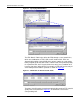
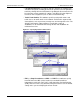
Specialized Models User Guide 6 MPLS Model User Guide Available Statistics To analyze MPLS performance, you can collect path statistics on end-to-end delay, utilization, and the amount of traffic on the LSP. These statistics can be collected on a per-flow or per LSP basis, where flows are individual flows of traffic within an LSP. Figure 6-14 Selecting Statistics to Collect When analyzing your MPLS network, you may also want to look at the routes used for the LSPs.
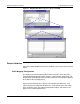
Specialized Models User Guide 6 MPLS Model User Guide Configuring MPLS in a Network Configuring MPLS in a network is a three-step process. Before you can run a simulation using MPLS, you must 1) Create LSPs in the network topology 2) Create FECs and traffic trunks in the MPLS Configuration object 3) Configure LERs to direct packets into the appropriate LSPs After this basic configuration is in place, you can add QoS/differentiated services (DiffServ) constraints or traffic shaping parameters.
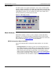
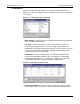
Specialized Models User Guide 6 MPLS Model User Guide 2 If you have not assigned IP addresses to all connected interfaces in the network, click the “Perform Auto-Assignment” button. Otherwise, click the “Skip Auto-Assignment” button. ➥ The MPLS Configuration dialog box opens. This box shows all the traffic pairs configured in the network with suggested configuration for LSP configuration.
Specialized Models User Guide 6 MPLS Model User Guide Constrained OSPF (CSPF) is used to implement constraint-based routing of LSPs. You can configure dynamic LSPs to use constraint-based routing in the LSP’s TE Parameters attribute by setting the Bandwidth, Delay, and Hop Count constraints.
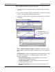
Specialized Models User Guide 6 MPLS Model User Guide Creating FECs and Traffic Trunks The traffic engineering bindings that govern how packets are labeled and forwarded in a network use FECs and traffic trunks to classify packets. All of the FECs and traffic trunks in a network are defined in the MPLS configuration object. Procedure 6-4 Creating FECs 1 Place an MPLS configuration object in the project workspace and open its Attributes dialog box. 2 Double-click on the value for FEC Specifications.
Specialized Models User Guide 6 MPLS Model User Guide Creating TE Bindings on LERs After you create the LSPs, FECs, and traffic trunks, you can create TE bindings that govern which packets are sent to which LSPs. You do this in the LER’s MPLS Parameters ➘ Traffic Mapping Configuration attribute. Procedure 6-6 Creating a TE Binding 1 Open the LER’s Traffic Mapping Configuration attribute dialog box (MPLS Parameters ➘ Traffic Mapping Configuration). 2 Add a row to the table.
Specialized Models User Guide 6 MPLS Model User Guide Exporting LSP Configuration Details for Use in Other Scenarios You can reuse LSPs that you have configured elsewhere by exporting the LSP configuration details to an ASCII file and using this file to create LSPs in the network. Procedure 6-7 Exporting LSP Configuration to an ASCII File 1 From the Protocols > MPLS menu, choose Browse/Edit LSP Information.... ➥ The LSP Browser appears.
Specialized Models User Guide 6 MPLS Model User Guide Applying QoS to an MPLS Network Model Differential Services (DiffServ) extensions can be used to apply quality-of-service constraints to your MPLS network model.
Specialized Models User Guide 6 MPLS Model User Guide If you change the queuing scheme later, make sure you reset the queuing profile because the order of these steps is important. Figure 6-15 Configuring QoS on an LER Always set the Queuing Scheme before setting the Queuing Profile. SPM-6-20 Modeler/Release 10.
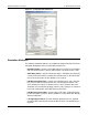
Specialized Models User Guide 6 MPLS Model User Guide MPLS Menu Operations The Protocols > MPLS menu enables you to configure, edit, and display MPLS features in the network topology. With the MPLS menu operations, you to streamline the MPLS configuration process. Table 6-3 lists the operations available from the Project Editor’s Protocols > MPLS menu. Table 6-3 MPLS Menu Summary Menu Item Description Update LSP Details Updates all static LSPs with label switching information.
Specialized Models User Guide 6 MPLS Model User Guide Information for OPNET Modeler Users The rest of this document contains information for model developers (such as OPNET Modeler users). The following sections describe the topics necessary for understanding the internal details of and interfacing to the MPLS model. Model Architecture Each node that can use MPLS has an IP module, which contains a dispatcher process that spawns MPLS processes.