
Computer Hardware User Manual

Input/Output Connectors
Input/Output Connectors
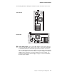
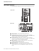
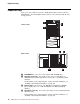
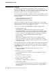
The following illustrations identify the connectors located on the back of the server.
.1/ Power Connector: The server power cable connects here.
.2/ Serial Connector A: Signal cables for modems or other serial devices
connect here to the 9-pin serial connector for serial port A. See “Devices and
I/O Ports” on page 23 for port assignment information.
.3/ Serial Connector B: Signal cables for modems or other serial devices
connect here to the 9-pin serial connector for serial port B. See “Devices and
I/O Ports” on page 23 for port assignment information.
.4/ Mouse Connector: The mouse cable connects here. This connector is
sometimes called the auxiliary-device port.
.5/ Keyboard Connector: The keyboard cable connects here.
.6/ Ethernet Connector: An unshielded, twisted-pair cable with an RJ-45
connector attaches here to the 10/100 Ethernet controller on the system
board.
Tower model
Rack model
12 Netfinity 5000 Server Hardware Information and Procedures