
Computer Hardware User Manual
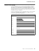
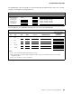

System Board Connectors
33
34
37
32
35
38
31
36
39
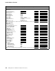
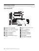
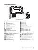
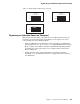
System Board Connectors
.1/ Systems management adapter connector
(J21)
.2/ Fan 2 connector (J6)
.3/ System switch block (SW1)
.4/ Microprocessor 2 connector (U21)
.5/ Reserved (J1)
.6/ Microprocessor 1 connector (U2)
.7/ Power connector (J3)
.8/ Reserved (J8)
.9/ Power connector (J4)
.1ð/ Reserved (J12)
.11/ Power supply data connector (J10)
.12/ Voltage regulator module (VRM) connector
(U20)
.13/ Fan 1 connector (J13)
.14/ DIMM 1 (J15), DIMM 2 (J16), DIMM 3 (J17),
and DIMM 4 (J22) connectors
.15/ SCSI connector (J18)
.16/ Diskette drive connector (J23)
.17/ IDE connector (J3)
.18/ Operator LED panel (J29)
.19/ Reserved (J31)
.2ð/ Power-on switch panel (J34)
.21/ RS-485 connector (J35)
.22/ Reserved (J37)
.23/ Reserved (J36)
.24/ Reserved (J41)
.25/ Reserved (J39)
.26/ Reserved (J32)
.27/ ISA connector (J40)
.28/ PCI/ISA connector, PCI bus 1 (J38)
.29/ PCI connector, PCI bus 1 (J33)
.3ð/ PCI connector, PCI bus 1 (J30)
.31/ Battery
.32/ PCI connector, PCI bus 1 (J28)
.33/ PCI connector, PCI bus 0 (J24)
.34/ Parallel/SCSI connectors (J19)
.35/ Video port and Management C port
connectors (J11) (Management C port
connector is above the video connector.)
.36/ USB 1 and USB 2 port connectors (J9)
(USB 2 is below USB 1)
.37/ Ethernet connector (J7)
.38/ Mouse and keyboard connectors (J5)
(The mouse connector is above the
keyboard connector)
.39/ Serial port A and B connectors (J2) (Serial
port B is below serial port A)
Chapter 7. Server Records and Specifications 169