MODEL: IBM-4900 ADVANCED HOME/OFFICE 4 LINE CORDLESS TELEPHONE WITH CALLER ID INSTALLATION AND OPERATION GUIDE Please read this manual carefully prior to installing your telephone. SMARTHOME.COM™ 1-800-SMART-HOME 949-221-9200 http://www.smarthome.
FCC INFORMATION.. ....................................................................................................................................................... 5 IMPORTANT SAFETY INSTRUCTIONS ..................................................................................................................... .6 BATTERY CAUTIONARY INSTRUCTIONS.. ............................................................................................................. .7 GETTING STARTED ....................
28 Automatic Redial. ........................................................................................................................................................... HEADSET OPERATION ................................................................................................................................................. 29 Connecting a Headset .................................................................................................................................................
Equipment Notes: Your IBM-4900 telephone is registered with the Federal Communications Commission and is in compliance with Part I5J and Part 68 of the FCC Rules and Regulations. On the bottom of this equipment is a label indicating among other information, the FCC Registration Number and Ringer Equivalence Number (REN) for the equipment. You must, upon request, provide this information to your telephone company.
Before using your telephone equipment, basic safety precautions should always be followed to reduce the risk of fire, electrical shock and injury to persons, including the following: Read and understand all instructions. Follow all warnings and instructions marked on the product. Unplug this product from the wall telephone jack and power outlet before cleaning. Do not use liquid cleaners or aerosol cleaners. Use a damp cloth for cleaning.
BATTERIES: CAUTION For the base of the telephone, use only ies. (batteries not included.) For the cordless handset, use only phone replacement battery packs. I . 5 volt, AA-size batteries, ( I 5a) carbon or alkaline. batter- 3.6V 600 mAh Nickel Cadmium (Ni-Cd) GP T143 cordless tele- Do not dispose of the batteries in a fire. The cells may explode. Check with local codes for possible special disposal instructions. Do not open or mutilate the batteries.
PACKAGE CONTENTS I. Check to be sure that you have all the following components in the package: 2. Telephone base. 3. Cordless Handset. 4. Headset for Cordless Handset. 5. Handset Battery Pack. 6. Handset Belt Clip. 7. Handset Antenna. 8. Normal length telephone line cord (2 PC’S). 9. Short length telephone line cord (I PC). IO. AC power adapter. I I. Quick Reference Guide 12. This instruction manual.
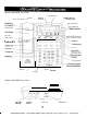
Model IBM-4900 Top View Do Not Disturb Key Call Timer Clock and Calendar Set , \ Disp’ay \ / /“:“I From Disp’ay Page All Extensions New Call/Message Handset Cradle Handset Catch P__I______ I/_.. Mute Key / I Hold Key Speaker Volume Model IBM-4900 Rear View L3/L4 Jack Ll/L2 Jack DATA Jack ADAPTER Jack SMARTHOME.COM™ 1-800-SMART-HOME 949-221-9200 http://www.smarthome.
Model IBM-4900 Display Dial from Caller ID Dis- LCD Call Timer Clock and Calendar Set play r / Page All Extensions \ \ / \ ’ New Calls and Message /d y Waiting LED G 5&r, Caller ID Mode Select & Scroll Keys for Erase Caller ID Line Toggle Caller ID Records Caller ID Records Erase Caller ID Records SET TIMER = / 4-I Model IBM-4900 Cordless Handset nH Headset Jack \ Handset Antenna Speaker Flash Battery Low Indicator Redial Lines 1-4 Keys Talk Intercom End Hold Dial Keypad cMFi & c ----r o p
USEFUL FEATURES AND TERMS as call waiting. Headset Integration - The included headset may be used as a substitute to the handset, allowing hands free conversation. Auto Line Selection - Automatically selects first available line for outgoing calls. Automatically selects ringing line for incoming calls. Hold - Permits user to place a call on hold. Allows access by that user or by any other extension in the system. Auto Redial - Redials the last number dialed approximately every 60 seconds.
LED Status Indication Off Line is not in use Flashing Slowly Incoming outside call is ringing On Steady Line is in use by another extension or phone line is not connected Flashing Rapidly Line is on hold by your extension Lines l-4 To that Line.
Idle Display Low Battery Display The telephone will indicate that the batteries are low (or not installed) by displaying a low battery indicator, “BAlT”, on the display. . _F! vt:. ..*. : I .I. .! ../pi t L “I. F, 1 gj i.I. :i 2 .I i:q. . . :j1. [::I. . . . . ,::.. . . . !:i. I / Si! Ei;i i:-i “r ..; Dialing Display As you dial 12345, the display shows the numbers dialed and begins the call timer.
First time The phone is idle i 2A 1 2B 3B 3A 1 t t 1 4 Press [CALL ID] Display Priority When the phone is handling simultaneous functions, messages are displayed according to the following precedence: 5. Caller ID data I. Dialed digits 2. Intercom operations 4. Programming functions I4 SMARTHOME.COM™ 1-800-SMART-HOME 949-221-9200 http://www.smarthome.
SELECTING A LOCATION TO INSTALL YOUR TELEPHONE The telephone may be used on a desk or mounted on a wall. Locate the base for optimal performance. Where you place the telephone base unit affects the reception quality of the handset. Choose the best location by following these suggestions: I. Place the base in a central location for optimal coverage. 2. Place the base near an AC electrical outlet and near telephone line jacks. 3. Place the base away from metal walls and metal file cabinets. 4.
INSTALLING THE BATTERIES The telephone base requires three 1.5 volt, AA-size batteries, preferably alkaline, (batteries not included). These batteries are required for the retention of user programmed settings and Caller ID data during a power outage. The BE-4900 does not require the AA batteries to be installed for normal operation. NOTE: In the event ofo power outage, your IBM-4900 telephone will not operate until power is restored. To install the AA batteries: I.
CONNECTING YOUR TELEPHONE LINES Wherever you intend to locate each phone, have your local telephone company install as many telephone lines and wall jacks as necessary to enable you to connect each telephone. If possible, have 2 two-line (RJ 14) wall jacks installed instead of 4 single-line (RJ I I) wall jacks (see illustrations on pages I8 and 19). Each telephone must be connected to each telephone line in order for it to access every line in the system. I.
SINGLE LINE JACKS RJ 11 JACK LINE 1 TWO LINE JACKS RJ 11 JACK RJ 14 JACK RJ 14 JACK LINE 2 CAUTION: Never install telephone wiring during a lightning storm. Never install telephone jacks in wet locations unless the jack is specifically designed for wet locations. Never touch un-insulated telephone wires or terminals unless the incoming telephone line has been disconnected at the network interface. Use caution when installing or modifying telephone lines. I8 SMARTHOME.
FOUR SINGLE LINE JACKS RJ 11 JACK RJ 11 JACK RJ 11 JACK RJ 11 JACK TWO LINE COUPLER TWO LINE COUPLER DESK OR TABLE TOP INSTALLATION I. For lines I and 2, plug a telephone line cord (provided with the phone) into the port L I/L2 as indicated on the rear base of the phone. 2. For lines 3 and 4, plug the other telephone line cord (provided with the phone) into the port L3/ L4 as indicated on the rear base of the phone. Insert the AC adapter cable into the port labeled ADAPTER in the rear of the phone.
ADJUSTING THE VIEWING ANGLE BRACKETS Adjust the viewing angle brackets (one on each side of the phone) to position the phone to the desired viewing angle. Take care to keep the right side bracket on the right side of the phone and the left bracket on the left side of the phone. These brackets are not interchangeable. The character R or L appears on the inside of each bracket to indicate proper installation. The brackets are adjusted by removing them from the base and reattaching them at desired angle.
WALL MOUNTING INSTRUCTIONS: I. Remove up the remote handset from the base. 2. Turn the phone upside down so the underside of the phone faces you. 3. Press down and out on the two tabs located on top of the wall/desk adapter and remove. 4. Rotate the wall/desk adapter a half turn and snap it into the wall mount position as shown below. 5. If mounting over a telephone wall jack, plug the supplied short 7 inch length telephone cord into the LI/L2 jack on the telephone. Thread the the phone.
LIST OF SYSTEM DEFAULTS The default telephone setup is as follows: Function Default Tone/Pulse Mode Tone Headset Disable Extension Number II Ringer On - 4 lines Line Connection On - 4 lines Speaker Volume 12th level Handset Volume Middle level Headset Volume Middle level Ringer Volume Middle level Speed Dial Empty Area Code Calendar Empty Jan 0 I Fr I2:OO am Caller ID Log Empty You may clear all programmed data and all the parameters will revert to the above default values.
NOTE: The programmable speed dial keys double in function as Direct, Station to Station (DSS) keys. The upper most lefl key is extension (Station) I I, the next key to the right is extension 12. etc. When using the features intercom (KM) and page, extensions may be dialed by pressing these keys even aper each key has also been programmed as a speed dial number. SETTING THE CLOCK AND CALENDAR The time and date appear on the display screen when the phone is not in use. To set the clock and calendar: I.
2. Press [5]. 3. Press a digit X where X is for line numbers I-4. 4. Press [0], [I] for ON, or [0], [0] for OFF. 5. Press [MUTE]. 6. A short ring will be heard to signal successful programming. PROGRAMMING RINGER ON/OFF The ringer may be turned OFF and ON for incoming calls on a line-by-line basis. To set the ringer value for an individual phone line: I. Press [STORE]. 2. Press [2]. 3. Press a digit X where X is for lines I-4 4. Press [0], [i] for ON or [O], [0] for OFF. 5. Press [MUTE]. 6.
AREA CODE PROGRAMMING This feature allows calls to be stored as a local call and dialed back using the [DIAL] key as a local call (the area code will not be dialed). There is storage for one local area code. Once you program the local area code, any incoming phone call from that area code will have the area code deleted automatically. Any phone call received prior to area code programming will be stored with the area code and dialed with the area code until deleted from the Caller ID log.
MAKING AN OUTGOING CALL The IBM-4900 base was designed to provide the utmost in dialing convenience. Access to most features is intended to start with the large, easily accessible keys found on the base. This means that many features are most easily accessed by first using the hands-free speakerphone, and then lifting the handset from the cradle for handset usage. Using the Speakerphone (hands free) I. Press the [SPKR] key. The first available line is automatically selected. 2. Dial the desired number.
Switching from Handset to Speakerphone I. Press the [SPKR] key. 2. Return handset to the cradle. ANSWERING AN INCOMING CALL Using the Speakerphone (hands free) Simply press the speakerphone [SPKR] key to be automatically connected to the ringing line, or, press the flashing [LINE] key on the telephone base to be connected with the outside call. Using the Handset If the handset is sitting in the handset cradle (preferred): I .Lift the handset. You will automatically be connected to the ringing line. 2.
To cancel mute Press the [MUTE] key again to restore the sound to the other party. The [MUTE] LED will turn off. LAST NUMBER REDIAL The IBM-4900 automatically stores the last phone number dialed. To redial that number: I. Press the [REDIAL] key on the base or the [REDIAL] key on the handset. The phone will automatically select the first available line and dial the last number dialed.
Your IBM-4900 comes with a convenient belt clip and a headset jack. The headset jack gives you the option of using a cordless phone headset which, when used with the IBM-4900 belt clip, provides hands-free convenience. A cordless telephone type headset utilizing a 2.5 mm connector plug has been included with your telephone. Connecting the Headset to the Handset I. Open the small rubber headset jack plug on the top of the handset. 2. Insert the 2.5 mm headset plug into this headset jack. 3.
The Intercom function allows extension-to-extension conversations (all phones must be connected to Line I). This means you can speak with another party without having to dial seven digits (using an outside line). As you place an intercom call to an extension that extension will ring, display “ICM” and your extension number on the LCD, and the [ICM] LED (on the base) will flash. NOTE: The IBM-4900, IBM-412, and IBM-412CID 4-line telephones support one intercom call at CJ time.
INTERCOM NOTES: I. If the called number is idle, you will hear an ICM ring back tone. 2. If the called number is busy (with an outside call), you will hear a busy ICM tone. The called party will hear a double ring and see the [ICM] LED flashing, indicating intercom call waiting. 3. If the called number is set on Do Not Disturb (DND), you will hear an ICM busy tone. The called “ICM” will appear on the party will not hear anything, but that extension’s [ICM] LED will flash and display.
Paging differs from Intercom calling in that the party called does not have to answer the phone in order to hear your message. This permits the caller to broadcast a message to one individual extension or all phone extensions at once. Messages can be heard by any idle extension connected to line I whose Do Not Disturb function is not active. PAGING AN INDIVIDUAL EXTENSION With the Speakerphone I. Press the [PAGE] key on the base. 2.
ANSWERING AN INDIVIDUAL PAGE With the Speakerphone I. Press the [MUTE] key and begin your conversation. 2. To end the conversation press the [SPKR] key. With the Handset I. Lift the handset from the cradle and begin your conversation, you will be automatically connected to the party paging you. 2. To end the call return the handset to the cradle or press the [END] key. PAGING ALL EXTENSIONS (PAGE ALL) The Page All feature is a great method for getting a message to everyone in your office.
This feature requires Caller ID subscription from the local telephone company. If you have multiple phone lines, you need to subscribe to Caller ID service on each line (defined as each different phone number) in order for Caller ID to display on those lines. CALLER IDENTIFICATION DISPLAY Caller ID Displayed when Phone is Idle I. The phone rings, signaling an outside call. 2. The display shows the caller’s name and number and line that the call is coming in on. 3.
Viewing the Caller ID Log I. Press the [ 41 or [,I keys, beneath the display, to scroll through the Caller ID list. 2. Upon the first press of either [ 41 or [ .] a call summary screen will appear. This screen displays the total number of calls stored in the Caller ID log as well as the number of new calls. New calls are calls which have not been previously viewed.
I. Using the [ 41 or [ .] key, find the particular record you would like to delete. 2. Press the [ERASE] key. The LCD display will indicate that the record has been deleted. 3. You may erase all caller information records simultaneously by pressing [ERASE] from the summary Call ID display. Returning a Call on the Caller’s List When reviewing Caller ID entries, you may decide to return a particular call immediately. T O do this: Press either the [ 41 or [ .
NEW CALL/MESSAGE WAITING INDICATOR This LED indicator is located at the lower right corner of the phone display. It functions as both a ‘New Calls’ and a ‘Message Waiting’ (voice mail) indicator. Calls Indicator The new calls indicator (LED) will light whenever the phone receives a call. The LED light will be constant (non-flashing). Once the new calls have been reviewed by scrolling through the Caller ID log, the light will go out.
Conference Call with an External Party I. While in conversation, press the [HOLD] key and make the second call on another available line. 2. After the third party has answered, press the [CONF] key. 3. Your three-way conference call has now been established. Conference Call with an Internal Party I. While in conversation, press the [HOLD] key and make the second call via the intercom function. 2. After the third party has answered, press the [CONF] key. 3.
PAUSE You may use this feature to create a dialing pause between digits during a call. Typically, the PAUSE function is most useful for programming dialing delays in long number sequences of certain Speed Dial numbers such as voicemail codes, international phone numbers, and personal banking authorizations. Each time you press the [REDIAL] key, you add a three second delay to the dialing sequence (you may do this more than once to create a longer delay.
Dialing Numbers in the First Speed Dial Group I. Press the [SPEED DIAL] key. The phone will access the first available line and automatically dial the stored number. The number will be shown on the display. Dialing Numbers in the Second Speed Dial Group I. Press the [SHIFT] key. The [SHIFT] LED will light. 2. Press the [SPEED DIAL] key to automatically access an available line and the extension will automatically dial the stored number. Erasing First Group Speed Dial Numbers I. Press the [STORE] key. 2.
CALL TIMER With the IBM-4900 you can keep track of the length of each phone call. The timer automatically begins as soon as the phone goes “off-hook”. The call timer appears on the lower line of the display. You can reset the timer if you don’t want it to begin until the other party answers the phone. I. Press [SHIFT] + FIMER] to stop the timer. 2. Press [SHIFT] + FIMER] again to start it over at 0O:OO.
Flash Rate for Lights On Steady: Solid light. Flashing Slowly: I set on, I set off, repeatedly. Flashing Rapidly: 0. I25 set on, 0. I25 set off, repeatedly. Blink I: I .875 set on, 0. I25 set off, repeatedly. Blink 2: 0.875 set on, 0. I25 set off, repeatedly. Blink 3: 0. I25 set on, 0.875 set off, repeatedly. Sound Rate of Intercom Buzzer Ring: 0.25 set on. Double ring: 0.25 set on, 0.25 set off, 0.25 set on, 0.25 set off. ICM ring: 0.25 set on, 0.25 set off, 0.25 set on, I .
Your IBM-4900 telephone has been designed to give years of trouble free service. It is a sensitive electromechanical instrument. To assure its longevity, please read the following maintenance instructions. I. Keep the IBM-4900 away from heat as high temperatures can shorten the life of the electrical components and distort or melt its plastic parts. 2. The IBM-4900 should be kept free of dust and moisture. If it gets wet, wipe it dry immediately.
Intercom, line status, auto-answer, privacy or auto-line selection are inoperable. Check if Lines I and 2 are cross wired in the wall jack. If used, see if you may have installed your 2-line adapter incorrectly. Be sure all extensions in the system are connected to [LINE I]. Check the assigned extension codes, making sure they are unique. Be sure the length of cable between stations does not exceed 300 feet.
Intercom service doesn’t appear to work. ) Check to make sure the phone lines for all extensions are set up consistently, meaning that all phones are properly wired for [LINE I], 2, 3 and 4. Review “Connecting Your Telephone Lines” section. The caller’s name and/or phone number does not appear on the display. ) Make sure you have subscribed to Caller ID Service (from local telephone company). ) Caller ID service may not work when the phone is connected to a Private Branch Exchange (PBX).