Cisco Systems Intelligent Gigabit Ethernet Switch Modules for the IBM BladeCenter Software Configuration Guide Cisco IOS Release 12.
Note: Before using this information and the product it supports, read the general information in Appendix C, “Getting Help and Technical Assistance” and Appendix D, “Notices.” First Edition (October 2005) © Copyright International Business Machines Corporation 2005. All rights reserved. US Government Users Restricted Rights – Use, duplication or disclosure restricted by GSA ADP Schedule Contract with IBM Corp.
C O N T E N T S Preface xxiii Audience Purpose xxiii xxiii Conventions xxiv Related Publications CHAPTER 1 Overview xxv 1-1 Features 1-1 Ease of Use and Ease of Deployment 1-1 Performance 1-1 Manageability 1-2 Redundancy 1-3 VLAN Support 1-4 Security 1-4 Quality of Service and Class of Service 1-5 Monitoring 1-5 Management Options 1-6 Management Interface Options Network Configuration Examples Where to Go Next CHAPTER 2 1-7 1-8 Using the Command-Line Interface Cisco IOS Command Modes Gettin
Contents Using Editing Features 2-6 Enabling and Disabling Editing Features 2-6 Editing Commands through Keystrokes 2-7 Editing Command Lines that Wrap 2-8 Searching and Filtering Output of show and more Commands Accessing the CLI CHAPTER 3 2-9 2-9 Assigning the Switch IP Address and Default Gateway Understanding the Boot Process 3-1 3-1 Assigning Switch Information 3-2 Default Switch Information 3-2 Manually Assigning IP Information 3-3 Checking and Saving the Running Configuration 3-4 Modifyi
Contents Configuring a System Name and Prompt 4-13 Default System Name and Prompt Configuration Configuring a System Name 4-14 Understanding DNS 4-14 Default DNS Configuration 4-15 Setting Up DNS 4-15 Displaying the DNS Configuration 4-16 Creating a Banner 4-16 Default Banner Configuration 4-16 Configuring a Message-of-the-Day Login Banner Configuring a Login Banner 4-18 4-14 4-16 Managing the MAC Address Table 4-18 Building the Address Table 4-19 MAC Addresses and VLANs 4-19 Default MAC Address Table C
Contents Identifying the TACACS+ Server Host and Setting the Authentication Key 5-12 Configuring TACACS+ Login Authentication 5-13 Configuring TACACS+ Authorization for Privileged EXEC Access and Network Services Starting TACACS+ Accounting 5-16 Displaying the TACACS+ Configuration 5-16 5-15 Controlling Switch Access with RADIUS 5-16 Understanding RADIUS 5-17 RADIUS Operation 5-18 Configuring RADIUS 5-19 Default RADIUS Configuration 5-19 Identifying the RADIUS Server Host 5-19 Configuring RADIUS Login Au
Contents Using IEEE 802.1x with Port Security 6-7 Using IEEE 802.1x with Voice VLAN Ports 6-8 Using IEEE 802.1x with VLAN Assignment 6-8 Using IEEE 802.1x with Guest VLAN 6-9 Using IEEE 802.1x with Wake-on-LAN 6-10 Unidirectional State 6-10 Bidirectional State 6-10 Configuring IEEE 802.1x Authentication 6-11 Default IEEE 802.1x Configuration 6-11 IEEE 802.1x Configuration Guidelines 6-12 Enabling IEEE 802.
Contents Configuration Guidelines 7-11 Setting the Interface Speed and Duplex Parameters Adding a Description for an Interface 7-12 7-11 Monitoring and Maintaining the Interfaces 7-13 Monitoring Interface and Controller Status 7-13 Clearing and Resetting Interfaces and Counters 7-15 Shutting Down and Restarting the Interface 7-15 CHAPTER 8 Configuring Smartports Macros 8-1 Understanding Smartports Macros 8-1 Configuring Smartports Macros 8-2 Default Smartports Macro Configuration 8-2 Smartports Ma
Contents Configuring Spanning-Tree Features 9-11 Default Spanning-Tree Configuration 9-12 Spanning-Tree Configuration Guidelines 9-12 Changing the Spanning-Tree Mode 9-13 Disabling Spanning Tree 9-14 Configuring the Root Switch 9-15 Configuring a Secondary Root Switch 9-17 Configuring the Port Priority 9-17 Configuring the Path Cost 9-19 Configuring the Switch Priority of a VLAN 9-20 Configuring Spanning-Tree Timers 9-21 Configuring the Hello Time 9-21 Configuring the Forwarding-Delay Time for a VLAN 9-22
Contents Configuring the Switch Priority 10-18 Configuring the Hello Time 10-18 Configuring the Forwarding-Delay Time 10-19 Configuring the Maximum-Aging Time 10-20 Configuring the Maximum-Hop Count 10-20 Specifying the Link Type to Ensure Rapid Transitions Restarting the Protocol Migration Process 10-21 Displaying the MST Configuration and Status CHAPTER 11 Configuring Optional Spanning-Tree Features 10-21 10-22 11-1 Understanding Optional Spanning-Tree Features Understanding Port Fast 11-2 Underst
Contents VLAN Configuration Mode Options 12-6 VLAN Configuration in config-vlan Mode 12-6 VLAN Configuration in VLAN Configuration Mode Saving VLAN Configuration 12-7 Default Ethernet VLAN Configuration 12-7 Creating or Modifying an Ethernet VLAN 12-8 Deleting a VLAN 12-10 Assigning Static-Access Ports to a VLAN 12-10 Configuring Extended-Range VLANs 12-11 Default VLAN Configuration 12-12 Extended-Range VLAN Configuration Guidelines Creating an Extended-Range VLAN 12-12 Displaying VLANs 12-6 12-12 12-13
Contents Monitoring the VMPS 12-30 Troubleshooting Dynamic Port VLAN Membership VMPS Configuration Example 12-31 CHAPTER 13 Configuring VTP 12-31 13-1 Understanding VTP 13-1 The VTP Domain 13-2 VTP Modes 13-3 VTP Advertisements 13-3 VTP Version 2 13-4 VTP Pruning 13-4 Configuring VTP 13-6 Default VTP Configuration 13-6 VTP Configuration Options 13-7 VTP Configuration in Global Configuration Mode 13-7 VTP Configuration in VLAN Configuration Mode 13-7 VTP Configuration Guidelines 13-8 Domain Names 13-8
Contents Configuring IGMP Snooping 14-7 Default IGMP Snooping Configuration 14-8 Enabling or Disabling IGMP Snooping 14-8 Setting the Snooping Method 14-9 Configuring a Multicast Router Port 14-10 Configuring a Host Statically to Join a Group 14-10 Enabling IGMP Immediate-Leave Processing 14-11 Configuring the IGMP Leave Timer 14-12 Disabling IGMP Report Suppression 14-12 Disabling IP Multicast-Source-Only Learning 14-13 Configuring the Aging Time 14-14 Displaying IGMP Snooping Information 14-14 Understa
Contents Default Port Security Configuration 15-6 Port Security Configuration Guidelines 15-6 Enabling and Configuring Port Security 15-7 Enabling and Configuring Port Security Aging 15-9 Displaying Port-Based Traffic Control Settings CHAPTER 16 Configuring UDLD 15-11 16-1 Understanding UDLD 16-1 Modes of Operation 16-1 Methods to Detect Unidirectional Links 16-2 Configuring UDLD 16-4 Default UDLD Configuration 16-4 Configuration Guidelines 16-4 Enabling UDLD Globally 16-5 Enabling UDLD on an Inter
Contents SPAN and RSPAN Session Limits 18-7 Default SPAN and RSPAN Configuration 18-7 Configuring SPAN 18-7 SPAN Configuration Guidelines 18-7 Creating a SPAN Session and Specifying Ports to Monitor 18-8 Creating a SPAN Session and Enabling Ingress Traffic 18-9 Removing Ports from a SPAN Session 18-11 Configuring RSPAN 18-12 RSPAN Configuration Guidelines 18-12 Configuring a VLAN as an RSPAN VLAN 18-13 Creating an RSPAN Source Session 18-14 Creating an RSPAN Destination Session 18-15 Removing Ports from
Contents Configuring UNIX Syslog Servers 20-10 Logging Messages to a UNIX Syslog Daemon Configuring the UNIX System Logging Facility Displaying the Logging Configuration CHAPTER 21 Configuring SNMP 21-1 21-4 Configuring SNMP 21-5 Default SNMP Configuration 21-5 SNMP Configuration Guidelines 21-6 Disabling the SNMP Agent 21-6 Configuring Community Strings 21-7 Configuring SNMP Groups and Users 21-8 Configuring SNMP Notifications 21-10 Setting the Agent Contact and Location Information Limiting TFTP Se
Contents Creating Named MAC Extended ACLs Creating MAC Access Groups 22-18 22-17 Applying ACLs to Terminal Lines or Physical Interfaces Applying ACLs to a Terminal Line 22-19 Applying ACLs to a Physical Interface 22-19 22-18 Displaying ACL Information 22-20 Displaying ACLs 22-20 Displaying Access Groups 22-21 Examples for Compiling ACLs 22-22 Numbered ACL Examples 22-23 Extended ACL Examples 22-23 Named ACL Example 22-23 Commented IP ACL Entry Examples CHAPTER 23 Configuring QoS 22-23 23-1 Unders
Contents Configuring the CoS Value for an Interface 23-19 Configuring Trusted Boundary 23-20 Enabling Pass-Through Mode 23-22 Configuring a QoS Policy 23-23 Classifying Traffic by Using ACLs 23-23 Classifying Traffic by Using Class Maps 23-27 Classifying, Policing, and Marking Traffic by Using Policy Maps 23-28 Configuring CoS Maps 23-31 Configuring the CoS-to-DSCP Map 23-32 Configuring the DSCP-to-CoS Map 23-33 Configuring the Egress Queues 23-34 Configuring CoS Priority Queues 23-34 Configuring WRR Prior
Contents Configuring Layer 2 Trunk Failover 24-16 Default Layer 2 Trunk Failover Configuration 24-16 Layer 2 Trunk Failover Configuration Guidelines 24-17 Configuring Layer 2 Trunk Failover 24-17 Displaying Layer 2 Trunk Failover Status CHAPTER 25 Troubleshooting 24-18 25-1 Using Recovery Procedures 25-1 Recovering from a Software Failure 25-1 Recovering from Lost or Forgotten Passwords 25-2 Password Recovery with Password Recovery Enabled Procedure with Password Recovery Disabled 25-5 Preventing Aut
Contents Changing Directories and Displaying the Working Directory Creating and Removing Directories B-4 Copying Files B-5 Deleting Files B-6 Creating, Displaying, and Extracting tar Files B-6 Creating a tar File B-6 Displaying the Contents of a tar File B-7 Extracting a tar File B-7 Displaying the Contents of a File B-8 B-4 Working with Configuration Files B-8 Guidelines for Creating and Using Configuration Files B-9 Configuration File Types and Location B-10 Creating a Configuration File By Using a Tex
Contents Copying Image Files By Using RCP B-28 Preparing to Download or Upload an Image File By Using RCP Downloading an Image File By Using RCP B-29 Uploading an Image File By Using RCP B-31 APPENDIX C Getting Help and Technical Assistance Before You Call C-1 C-1 Using the Documentation C-2 Getting Help and Information from the World Wide Web APPENDIX D Software Service and Support C-2 Hardware Service and Support C-2 Notices B-28 C-2 D-1 Edition Notice Trademarks D-2 D-2 INDEX Cisco
Contents Cisco Systems Intelligent Gigabit Ethernet Switch Modules for the IBM BladeCenter, Software Configuration Guide xxii 24R9746
Preface Audience This guide is for the networking professional managing the Cisco Systems Intelligent Gigabit Ethernet Switch Modules, hereafter referred to as the switch. Before using this guide, you should have experience working with the Cisco IOS and be familiar with the concepts and terminology of Ethernet and local area networking. Purpose This guide provides the information you need to configure software features on your switch.
Preface Conventions Conventions This publication uses these conventions to convey instructions and information: Command descriptions use these conventions: • Commands and keywords are in boldface text. • Arguments for which you supply values are in italic. • Square brackets ([ ]) mean optional elements. • Braces ({ }) group required choices, and vertical bars ( | ) separate the alternative elements.
Preface Related Publications Related Publications In addition to this document, the following related documentation comes with the Gigabit Ethernet switch module: • Note Cisco Systems Intelligent Gigabit Ethernet Switch Module for the IBM BladeCenter System Release Notes Switch requirements and procedures for initial configurations and software upgrades tend to change and therefore appear only in the release notes.
Preface Related Publications • BladeCenter Type 8677 Installation and User’s Guide This document is in PDF on the IBM BladeCenter Documentation CD.
C H A P T E R 1 Overview This chapter provides these topics about the Cisco Systems Intelligent Gigabit Ethernet Switch Module: Note • Features, page 1-1 • Management Options, page 1-6 • Network Configuration Examples, page 1-7 • Where to Go Next, page 1-8 In this document, IP refers to IP version 4 (IPv4). Layer 3 IP version 6 (IPv6) packets are treated as non-IP packets. Features This section describes the features supported in this release.
Chapter 1 Overview Features • Port blocking on forwarding unknown unicast and multicast traffic • Per-port broadcast storm control for preventing faulty end stations from degrading overall system performance with broadcast storms • Port Aggregation Protocol (PAgP) and Link Aggregation Control Protocol (LACP) for automatic creation of EtherChannel links • Internet Group Management Protocol (IGMP) snooping for IGMP versions 1, 2, and 3 to limit flooding of IP multicast traffic • IGMP report suppre
Chapter 1 Overview Features • Out-of-band management access through the switch service port to a directly-attached terminal or to a remote terminal through a serial connection and a modem Note For additional descriptions of the management interfaces, see the “Management Options” section on page 1-6.
Chapter 1 Overview Features VLAN Support • The switches support 250 port-based VLANs for assigning users to VLANs associated with appropriate network resources, traffic patterns, and bandwidth • The switch supports up to 4094 VLAN IDs to allow service provider networks to support the number of VLANs allowed by the IEEE 802.1Q standard • IEEE 802.
Chapter 1 Overview Features Quality of Service and Class of Service • Automatic quality of service (auto-QoS) to simplify the deployment of existing QoS features by classifying traffic and configuring egress queues • IEEE 802.
Chapter 1 Overview Management Options • Syslog facility for logging system messages about authentication or authorization errors, resource issues, and time-out events • Layer 2 traceroute to identify the physical path that a packet takes from a source device to a destination device Management Options The switch is designed for plug-and-play operation: you only need to assign basic IP information to the switch and connect it to the other devices in your network.
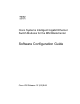
Chapter 1 Overview Network Configuration Examples Network Configuration Examples Figure 1-1, Figure 1-2, and Figure 1-3 show three different network configurations.
Chapter 1 Overview Where to Go Next Figure 1-3 Redundancy Configuration Cisco ESM For example, Catalyst 3750 Switch Firewall Network BladeCenter 126759 Server Server Server Server Ports 17–20 Where to Go Next Before configuring the switch, review these sections for start-up information: • Chapter 2, “Using the Command-Line Interface” • Chapter 3, “Assigning the Switch IP Address and Default Gateway” Cisco Systems Intelligent Gigabit Ethernet Switch Modules for the IBM BladeCenter, Software
C H A P T E R 2 Using the Command-Line Interface This chapter describes the Cisco IOS command-line interface (CLI) that you can use to configure your Cisco Systems Intelligent Gigabit Ethernet Switch Module.
Chapter 2 Using the Command-Line Interface Cisco IOS Command Modes Table 2-1 describes the main command modes, how to access each one, the prompt you see in that mode, and how to exit the mode. The examples in the table use the host name Switch. Table 2-1 Command Mode Summary Mode Access Method Prompt Exit Method About This Mode User EXEC Begin a session with your switch. Switch> Enter logout or quit. Use this mode to • Change terminal settings. • Perform basic tests.
Chapter 2 Using the Command-Line Interface Getting Help Table 2-1 Command Mode Summary (continued) Mode Access Method Prompt Exit Method About This Mode Interface configuration While in global configuration mode, enter the interface command (with a specific interface). Switch(config-if)# To exit to global configuration mode, enter exit. Use this mode to configure parameters for the interfaces. To return to privileged EXEC mode, press Ctrl-Z or enter end.
Chapter 2 Using the Command-Line Interface Abbreviating Commands Table 2-2 Help Summary (continued) Command Purpose command ? List the associated keywords for a command. For example: Switch> show ? command keyword ? List the associated arguments for a keyword. For example: Switch(config)# cdp holdtime ? <10-255> Length of time (in sec) that receiver must keep this packet Abbreviating Commands You have to enter only enough characters for the switch to recognize the command as unique.
Chapter 2 Using the Command-Line Interface Understanding CLI Messages Understanding CLI Messages Table 2-3 lists some error messages that you might encounter while using the CLI to configure your switch. Table 2-3 Common CLI Error Messages Error Message Meaning How to Get Help % Ambiguous command: "show con" You did not enter enough characters for your switch to recognize the command. Re-enter the command followed by a question mark (?) with a space between the command and the question mark.
Chapter 2 Using the Command-Line Interface Using Editing Features Recalling Commands To recall commands from the history buffer, perform one of the actions listed in Table 2-4: Table 2-4 Recalling Commands Action1 Result Press Ctrl-P or the up arrow key. Recall commands in the history buffer, beginning with the most recent command. Repeat the key sequence to recall successively older commands. Press Ctrl-N or the down arrow key.
Chapter 2 Using the Command-Line Interface Using Editing Features To reconfigure a specific line to have enhanced editing mode, enter this command in line configuration mode: Switch(config-line)# editing To globally disable enhanced editing mode, enter this command in line configuration mode: Switch(config-line)# no editing Editing Commands through Keystrokes Table 2-5 shows the keystrokes that you need to edit command lines.
Chapter 2 Using the Command-Line Interface Using Editing Features Table 2-5 Editing Commands through Keystrokes (continued) Capability Keystroke1 Purpose Scroll down a line or screen on displays that are longer than the terminal screen can display. Press the Return key. Scroll down one line. Press the Space bar. Scroll down one screen. Press Ctrl-L or Ctrl-R. Redisplay the current command line.
Chapter 2 Using the Command-Line Interface Searching and Filtering Output of show and more Commands Use line wrapping with the command history feature to recall and modify previous complex command entries. For information about recalling previous command entries, see the “Editing Commands through Keystrokes” section on page 2-7. Searching and Filtering Output of show and more Commands You can search and filter the output for show and more commands.
Chapter 2 Using the Command-Line Interface Accessing the CLI Cisco Systems Intelligent Gigabit Ethernet Switch Modules for the IBM BladeCenter, Software Configuration Guide 2-10 24R9746
C H A P T E R 3 Assigning the Switch IP Address and Default Gateway This chapter describes how to create the initial switch configuration (for example, assign the switch IP address and default gateway information) for the Cisco Systems Intelligent Gigabit Ethernet Switch Module. Note For complete syntax and usage information for the commands used in this chapter, see the command reference for this release and the Cisco IOS IP and IP Routing Command Reference, Release 12.1.
Chapter 3 Assigning the Switch IP Address and Default Gateway Assigning Switch Information The boot loader provides access to the flash file system before the operating system is loaded. Normally, the boot loader is used only to load, uncompress, and launch the operating system. After the boot loader gives the operating system control of the CPU, the boot loader is not active until the next system reset or power on.
Chapter 3 Assigning the Switch IP Address and Default Gateway Assigning Switch Information Manually Assigning IP Information You can configure multiple IP addresses for a switch. Each IP address and its subnet mask must be unique and belong to different subnets. You cannot configure IP addresses that cross other subnets on the switch. Each IP address must be assigned to a different VLAN interface. The switch can be managed from any valid IP address.
Chapter 3 Assigning the Switch IP Address and Default Gateway Checking and Saving the Running Configuration Command Purpose Step 4 management Enable the VLAN interface as the management VLAN. Step 5 exit Return to global configuration mode. Step 6 end Return to privileged EXEC mode. Step 7 show interfaces vlan vlan-id Verify the configured IP address. Step 8 show ip redirects Verify the configured default gateway.
Chapter 3 Assigning the Switch IP Address and Default Gateway Checking and Saving the Running Configuration switchport trunk allowed vlan 2-4094 switchport mode trunk storm-control broadcast level 99.99 99.98 spanning-tree bpdufilter enable ! interface GigabitEthernet0/2 description blade2 switchport access vlan 2 switchport trunk native vlan 2 switchport trunk allowed vlan 2-4094 switchport mode trunk ip access-group SecWiz_Gi0_2_in_ip in spanning-tree bpdufilter enable ! . . .
Chapter 3 Assigning the Switch IP Address and Default Gateway Modifying the Startup Configuration ! ip default-gateway 172.20.138.178 ip http server ! ip access-list extended SecWiz_Gi0_1_out_ip ip access-list extended SecWiz_Gi0_2_in_ip deny ip any host 1.1.1.
Chapter 3 Assigning the Switch IP Address and Default Gateway Modifying the Startup Configuration Default Boot Configuration Table 3-2 shows the default boot configuration. Table 3-2 Default Boot Configuration Feature Default Setting Operating system software image The switch attempts to automatically boot the system using information in the BOOT environment variable.
Chapter 3 Assigning the Switch IP Address and Default Gateway Modifying the Startup Configuration Booting a Specific Software Image By default, the switch attempts to automatically boot the system using information in the BOOT environment variable. If this variable is not set, the switch attempts to load and execute the first executable image it can by performing a recursive, depth-first search throughout the flash file system.
Chapter 3 Assigning the Switch IP Address and Default Gateway Modifying the Startup Configuration Table 3-3 Environment Variables Storage Location Environment Variable Location (file system:filename) BAUD, ENABLE_BREAK, CONFIG_BUFSIZE, CONFIG_FILE, MANUAL_BOOT, PS1 flash:env_vars BOOT, BOOTHLPR, HELPER, HELPER_CONFIG_FILE flash:system_env_vars Each line in these files contains an environment variable name and an equal sign followed by the value of the variable.
Chapter 3 Assigning the Switch IP Address and Default Gateway Modifying the Startup Configuration Table 3-4 describes the function of the most common environment variables. Table 3-4 Environment Variables Variable Boot Loader Command Cisco IOS Global Configuration Command MANUAL_BOOT set MANUAL_BOOT yes boot manual Decides whether the switch automatically or Enables manually booting the switch during the next boot cycle and changes the setting of manually boots.
Chapter 3 Assigning the Switch IP Address and Default Gateway Scheduling a Reload of the Software Image Scheduling a Reload of the Software Image You can schedule a reload of the software image to occur on the switch at a later time (for example, late at night or during the weekend when the switch is used less), or you can synchronize a reload network-wide (for example, to perform a software upgrade on all switches in the network). Note A scheduled reload must take place within approximately 24 days.
Chapter 3 Assigning the Switch IP Address and Default Gateway Scheduling a Reload of the Software Image This example shows how to reload the software on the switch at a future time: Switch# reload at 02:00 jun 20 Reload scheduled for 02:00:00 UTC Thu Jun 20 1996 (in 344 hours and 53 minutes) Proceed with reload? [confirm] To cancel a previously scheduled reload, use the reload cancel privileged EXEC command.
C H A P T E R 4 Administering the Switch This chapter describes how to perform one-time operations to administer your Cisco Systems Intelligent Gigabit Ethernet Switch Module.
Chapter 4 Administering the Switch Managing the System Time and Date The system clock can provide time to these services: • User show commands • Logging and debugging messages The system clock keeps track of time internally based on Universal Time Coordinated (UTC), also known as Greenwich Mean Time (GMT). You can configure information about the local time zone and summer time (daylight saving time) so that the time appears correctly for the local time zone.
Chapter 4 Administering the Switch Managing the System Time and Date Figure 4-1 Typical NTP Network Configuration Catalyst 6500 series switch (NTP master) Local workgroup servers Catalyst 2950, 2955, or 3550 switch Catalyst 2950, 2955, or 3550 switch Catalyst 2950, 2955, or 3550 switch BladeCenter 92439 These switches are configured in NTP server mode (server association) with the Catalyst 6500 series switch.
Chapter 4 Administering the Switch Managing the System Time and Date Default NTP Configuration Table 4-1 shows the default NTP configuration. Table 4-1 Default NTP Configuration Feature Default Setting NTP authentication Disabled. No authentication key is specified. NTP peer or server associations None configured. NTP broadcast service Disabled; no interface sends or receives NTP broadcast packets. NTP access restrictions No access control is specified.
Chapter 4 Administering the Switch Managing the System Time and Date Command Purpose Step 5 end Return to privileged EXEC mode. Step 6 show running-config Verify your entries. Step 7 copy running-config startup-config (Optional) Save your entries in the configuration file. To disable NTP authentication, use the no ntp authenticate global configuration command. To remove an authentication key, use the no ntp authentication-key number global configuration command.
Chapter 4 Administering the Switch Managing the System Time and Date Command Purpose Step 3 end Return to privileged EXEC mode. Step 4 show running-config Verify your entries. Step 5 copy running-config startup-config (Optional) Save your entries in the configuration file. You need to configure only one end of an association; the other device can automatically establish the association.
Chapter 4 Administering the Switch Managing the System Time and Date Step 6 Command Purpose copy running-config startup-config (Optional) Save your entries in the configuration file. Step 7 Configure the connected peers to receive NTP broadcast packets as described in the next procedure. To disable the interface from sending NTP broadcast packets, use the no ntp broadcast interface configuration command.
Chapter 4 Administering the Switch Managing the System Time and Date Creating an Access Group and Assigning a Basic IP Access List Beginning in privileged EXEC mode, follow these steps to control access to NTP services by using access lists: Command Purpose Step 1 configure terminal Enter global configuration mode. Step 2 ntp access-group {query-only | serve-only | serve | peer} access-list-number Create an access group, and apply a basic IP access list.
Chapter 4 Administering the Switch Managing the System Time and Date To remove access control to the switch NTP services, use the no ntp access-group {query-only | serve-only | serve | peer} global configuration command. This example shows how to configure the switch to allow itself to synchronize to a peer from access list 99.
Chapter 4 Administering the Switch Managing the System Time and Date The specified interface is used for the source address for all packets sent to all destinations. If a source address is to be used for a specific association, use the source keyword in the ntp peer or ntp server global configuration command as described in the “Configuring NTP Associations” section on page 4-5.
Chapter 4 Administering the Switch Managing the System Time and Date Displaying the Time and Date Configuration To display the time and date configuration, use the show clock [detail] privileged EXEC command. The system clock keeps an authoritative flag that shows whether the time is authoritative (believed to be accurate). If the system clock has been set by a timing source such as NTP, the flag is set. If the time is not authoritative, it is used only for display purposes.
Chapter 4 Administering the Switch Managing the System Time and Date Configuring Summer Time (Daylight Saving Time) Beginning in privileged EXEC mode, follow these steps to configure summer time (daylight saving time) in areas where it starts and ends on a particular day of the week each year: Command Purpose Step 1 configure terminal Enter global configuration mode. Step 2 clock summer-time zone recurring Configure summer time to start and end on the specified days every year.
Chapter 4 Administering the Switch Configuring a System Name and Prompt Beginning in privileged EXEC mode, follow these steps if summer time in your area does not follow a recurring pattern (configure the exact date and time of the next summer time events): Command Purpose Step 1 configure terminal Enter global configuration mode. Step 2 Configure summer time to start on the first date and end on the second clock summer-time zone date [month date year hh:mm month date year hh:mm date.
Chapter 4 Administering the Switch Configuring a System Name and Prompt This section contains this configuration information: • Default System Name and Prompt Configuration, page 4-14 • Configuring a System Name, page 4-14 • Understanding DNS, page 4-14 Default System Name and Prompt Configuration The default switch system name and prompt is Switch.
Chapter 4 Administering the Switch Configuring a System Name and Prompt This section contains this configuration information: • Default DNS Configuration, page 4-15 • Setting Up DNS, page 4-15 • Displaying the DNS Configuration, page 4-16 Default DNS Configuration Table 4-2 shows the default DNS configuration. Table 4-2 Default DNS Configuration Feature Default Setting DNS enable state Enabled. DNS default domain name None configured. DNS servers No name server addresses are configured.
Chapter 4 Administering the Switch Creating a Banner If you use the switch IP address as its hostname, the IP address is used and no DNS query occurs. If you configure a hostname that contains no periods (.), a period followed by the default domain name is appended to the hostname before the DNS query is made to map the name to an IP address. The default domain name is the value set by the ip domain-name global configuration command. If there is a period (.
Chapter 4 Administering the Switch Creating a Banner Beginning in privileged EXEC mode, follow these steps to configure a MOTD login banner: Command Purpose Step 1 configure terminal Enter global configuration mode. Step 2 banner motd c message c Specify the message of the day. For c, enter the delimiting character of your choice, for example, a pound sign (#), and press the Return key. The delimiting character signifies the beginning and end of the banner text.
Chapter 4 Administering the Switch Managing the MAC Address Table Configuring a Login Banner You can configure a login banner to be displayed on all connected terminals. This banner appears after the MOTD banner and before the login prompt. Beginning in privileged EXEC mode, follow these steps to configure a login banner: Command Purpose Step 1 configure terminal Enter global configuration mode. Step 2 banner login c message c Specify the login message.
Chapter 4 Administering the Switch Managing the MAC Address Table This section contains this configuration information: • Building the Address Table, page 4-19 • MAC Addresses and VLANs, page 4-19 • Default MAC Address Table Configuration, page 4-20 • Changing the Address Aging Time, page 4-20 • Removing Dynamic Address Entries, page 4-20 • Configuring MAC Address Notification Traps, page 4-21 • Adding and Removing Static Address Entries, page 4-23 • Displaying Address Table Entries, page 4
Chapter 4 Administering the Switch Managing the MAC Address Table Default MAC Address Table Configuration Table 4-3 shows the default MAC address table configuration. Table 4-3 Default MAC Address Table Configuration Feature Default Setting Aging time 300 seconds Dynamic addresses Automatically learned Static addresses None configured Changing the Address Aging Time Dynamic addresses are source MAC addresses that the switch learns and then ages when they are not in use.
Chapter 4 Administering the Switch Managing the MAC Address Table To verify that dynamic entries have been removed, use the show mac address-table dynamic privileged EXEC command. Configuring MAC Address Notification Traps MAC address notification enables you to track users on a network by storing the MAC address activity on the switch. Whenever the switch learns or removes a MAC address, an SNMP notification can be generated and sent to the NMS.
Chapter 4 Administering the Switch Managing the MAC Address Table Step 5 Command Purpose mac address-table notification [interval value] | [history-size value] Enter the trap interval time and the history table size. • (Optional) For interval value, specify the notification trap interval in seconds between each set of traps that are generated to the NMS. The range is 0 to 2147483647 seconds; the default is 1 second.
Chapter 4 Administering the Switch Managing the MAC Address Table Adding and Removing Static Address Entries A static address has these characteristics: • It is manually entered in the address table and must be manually removed. • It can be a unicast or multicast address. • It does not age and is retained when the switch restarts. You can add and remove static addresses and define the forwarding behavior for them.
Chapter 4 Administering the Switch Managing the ARP Table This example shows how to add the static address c2f3.220a.12f4 to the MAC address table. When a packet is received in VLAN 4 with this MAC address as its destination address, the packets is forwarded to the specified interface: Switch(config)# mac address-table static c2f3.220a.
C H A P T E R 5 Configuring Switch-Based Authentication This chapter describes how to configure switch-based authentication on the Cisco Systems Intelligent Gigabit Ethernet Switch Module.
Chapter 5 Configuring Switch-Based Authentication Protecting Access to Privileged EXEC Commands Protecting Access to Privileged EXEC Commands A simple way of providing terminal access control in your network is to use passwords and assign privilege levels. Password protection restricts access to a network or network device. Privilege levels define what commands users can enter after they have logged into a network device.
Chapter 5 Configuring Switch-Based Authentication Protecting Access to Privileged EXEC Commands Setting or Changing a Static Enable Password The enable password controls access to the privileged EXEC mode. Beginning in privileged EXEC mode, follow these steps to set or change a static enable password: Command Purpose Step 1 configure terminal Enter global configuration mode. Step 2 enable password password Define a new password or change an existing password for access to privileged EXEC mode.
Chapter 5 Configuring Switch-Based Authentication Protecting Access to Privileged EXEC Commands Protecting Enable and Enable Secret Passwords with Encryption To provide an additional layer of security, particularly for passwords that cross the network or that are stored on a TFTP server, you can use either the enable password or enable secret global configuration commands.
Chapter 5 Configuring Switch-Based Authentication Protecting Access to Privileged EXEC Commands If both the enable and enable secret passwords are defined, users must enter the enable secret password. Use the level keyword to define a password for a specific privilege level. After you specify the level and set a password, give the password only to users who need to have access at this level. Use the privilege level global configuration command to specify commands accessible at various levels.
Chapter 5 Configuring Switch-Based Authentication Protecting Access to Privileged EXEC Commands This example shows how to set the Telnet password to let45me67in89: Switch(config)# line vty 10 Switch(config-line)# password let45me67in89 Configuring Username and Password Pairs You can configure username and password pairs, which are locally stored on the switch. These pairs are assigned to lines or interfaces and authenticate each user before that user can access the switch.
Chapter 5 Configuring Switch-Based Authentication Protecting Access to Privileged EXEC Commands For example, if you want many users to have access to the clear line command, you can assign it level 2 security and distribute the level 2 password fairly widely. But if you want more restricted access to the configure command, you can assign it level 3 security and distribute that password to a more restricted group of users.
Chapter 5 Configuring Switch-Based Authentication Protecting Access to Privileged EXEC Commands This example shows how to set the configure command to privilege level 14 and define SecretPswd14 as the password users must enter to use level 14 commands: Switch(config)# privilege exec level 14 configure Switch(config)# enable password level 14 SecretPswd14 Changing the Default Privilege Level for Lines Beginning in privileged EXEC mode, follow these steps to change the default privilege level for a line:
Chapter 5 Configuring Switch-Based Authentication Controlling Switch Access with TACACS+ Controlling Switch Access with TACACS+ This section describes how to enable and configure TACACS+, which provides detailed accounting information and flexible administrative control over authentication and authorization processes. TACACS+ is facilitated through authentication, authorization, accounting (AAA) and can be enabled only through AAA commands.
Chapter 5 Configuring Switch-Based Authentication Controlling Switch Access with TACACS+ Figure 5-1 Typical TACACS+ Network Configuration UNIX workstation (TACACS+ server 1) Catalyst 6500 series switch 171.20.10.7 UNIX workstation (TACACS+ server 2) 171.20.10.8 BladeCenter Configure the switches with the TACACS+ server addresses. Set an authentication key (also configure the same key on the TACACS+ servers). Enable AAA. Create a login authentication method list.
Chapter 5 Configuring Switch-Based Authentication Controlling Switch Access with TACACS+ TACACS+ Operation When a user attempts a simple ASCII login by authenticating to a switch by using TACACS+, this process occurs: 1. When the connection is established, the switch contacts the TACACS+ daemon to obtain a username prompt to show to the user. The user enters a username, and the switch then contacts the TACACS+ daemon to obtain a password prompt.
Chapter 5 Configuring Switch-Based Authentication Controlling Switch Access with TACACS+ This section contains this configuration information: • Default TACACS+ Configuration, page 5-12 • Identifying the TACACS+ Server Host and Setting the Authentication Key, page 5-12 • Configuring TACACS+ Login Authentication, page 5-13 • Configuring TACACS+ Authorization for Privileged EXEC Access and Network Services, page 5-15 • Starting TACACS+ Accounting, page 5-16 Default TACACS+ Configuration TACACS+ a
Chapter 5 Configuring Switch-Based Authentication Controlling Switch Access with TACACS+ Step 4 Command Purpose aaa group server tacacs+ group-name (Optional) Define the AAA server-group with a group name. This command puts the switch in a server group subconfiguration mode. Step 5 server ip-address (Optional) Associate a particular TACACS+ server with the defined server group. Repeat this step for each TACACS+ server in the AAA server group.
Chapter 5 Configuring Switch-Based Authentication Controlling Switch Access with TACACS+ Beginning in privileged EXEC mode, follow these steps to configure login authentication: Command Purpose Step 1 configure terminal Enter global configuration mode. Step 2 aaa new-model Enable AAA. Step 3 aaa authentication login {default | list-name} method1 [method2...] Create a login authentication method list.
Chapter 5 Configuring Switch-Based Authentication Controlling Switch Access with TACACS+ To disable AAA, use the no aaa new-model global configuration command. To disable AAA authentication, use the no aaa authentication login {default | list-name} method1 [method2...] global configuration command. To either disable TACACS+ authentication for logins or to return to the default value, use the no login authentication {default | list-name} line configuration command.
Chapter 5 Configuring Switch-Based Authentication Controlling Switch Access with RADIUS Starting TACACS+ Accounting The AAA accounting feature tracks the services that users are accessing and the amount of network resources that they are consuming. When AAA accounting is enabled, the switch reports user activity to the TACACS+ security server in the form of accounting records. Each accounting record contains accounting attribute-value (AV) pairs and is stored on the security server.
Chapter 5 Configuring Switch-Based Authentication Controlling Switch Access with RADIUS Understanding RADIUS RADIUS is a distributed client/server system that secures networks against unauthorized access. RADIUS clients run on supported Cisco routers and switches. Clients send authentication requests to a central RADIUS server, which contains all user authentication and network service access information.
Chapter 5 Configuring Switch-Based Authentication Controlling Switch Access with RADIUS Figure 5-2 Remote PC Transitioning from RADIUS to TACACS+ Services Catalyst 2950, 2955, or 3550 switch 92438 TACACS+ server TACACS+ server RADIUS server RADIUS server BladeCenter RADIUS Operation When a user attempts to log in and authenticate to a switch that is access controlled by a RADIUS server, these events occur: 1. The user is prompted to enter a username and password. 2.
Chapter 5 Configuring Switch-Based Authentication Controlling Switch Access with RADIUS Configuring RADIUS This section describes how to configure your switch to support RADIUS. At a minimum, you must identify the host or hosts that run the RADIUS server software and define the method lists for RADIUS authentication. You can optionally define method lists for RADIUS authorization and accounting.
Chapter 5 Configuring Switch-Based Authentication Controlling Switch Access with RADIUS You identify RADIUS security servers by their host name or IP address, host name and specific UDP port numbers, or their IP address and specific UDP port numbers. The combination of the IP address and the UDP port number creates a unique identifier, allowing different ports to be individually defined as RADIUS hosts providing a specific AAA service.
Chapter 5 Configuring Switch-Based Authentication Controlling Switch Access with RADIUS Beginning in privileged EXEC mode, follow these steps to configure per-server RADIUS server communication. This procedure is required. Command Purpose Step 1 configure terminal Enter global configuration mode.
Chapter 5 Configuring Switch-Based Authentication Controlling Switch Access with RADIUS This example shows how to configure one RADIUS server to be used for authentication and another to be used for accounting: Switch(config)# radius-server host 172.29.36.49 auth-port 1612 key rad1 Switch(config)# radius-server host 172.20.36.
Chapter 5 Configuring Switch-Based Authentication Controlling Switch Access with RADIUS Step 3 Command Purpose aaa authentication login {default | list-name} method1 [method2...] Create a login authentication method list. • To create a default list that is used when a named list is not specified in the login authentication command, use the default keyword followed by the methods that are to be used in default situations. The default method list is automatically applied to all interfaces.
Chapter 5 Configuring Switch-Based Authentication Controlling Switch Access with RADIUS To disable AAA, use the no aaa new-model global configuration command. To disable AAA authentication, use the no aaa authentication login {default | list-name} method1 [method2...] global configuration command. To either disable RADIUS authentication for logins or to return to the default value, use the no login authentication {default | list-name} line configuration command.
Chapter 5 Configuring Switch-Based Authentication Controlling Switch Access with RADIUS Beginning in privileged EXEC mode, follow these steps to define the AAA server group and associate a particular RADIUS server with it: Command Purpose Step 1 configure terminal Enter global configuration mode.
Chapter 5 Configuring Switch-Based Authentication Controlling Switch Access with RADIUS Step 8 Command Purpose copy running-config startup-config (Optional) Save your entries in the configuration file. Step 9 Enable RADIUS login authentication. See the “Configuring RADIUS Login Authentication” section on page 5-22. To remove the specified RADIUS server, use the no radius-server host hostname | ip-address global configuration command.
Chapter 5 Configuring Switch-Based Authentication Controlling Switch Access with RADIUS Step 3 Command Purpose aaa authorization exec radius Configure the switch for user RADIUS authorization to determine if the user has privileged EXEC access. The exec keyword might return user profile information (such as autocommand information). Step 4 end Return to privileged EXEC mode. Step 5 show running-config Verify your entries.
Chapter 5 Configuring Switch-Based Authentication Controlling Switch Access with RADIUS Configuring Settings for All RADIUS Servers Beginning in privileged EXEC mode, follow these steps to configure global communication settings between the switch and all RADIUS servers: Command Purpose Step 1 configure terminal Enter global configuration mode. Step 2 radius-server key string Specify the shared secret text string used between the switch and all RADIUS servers.
Chapter 5 Configuring Switch-Based Authentication Controlling Switch Access with RADIUS For example, this AV pair activates Cisco’s multiple named ip address pools feature during IP authorization (during PPP’s IPCP address assignment): cisco-avpair= ”ip:addr-pool=first“ This example shows how to provide a user logging in from a switch with immediate access to privileged EXEC commands: cisco-avpair= ”shell:priv-lvl=15“ This example shows how to specify an authorized VLAN in the RADIUS server database: ci
Chapter 5 Configuring Switch-Based Authentication Controlling Switch Access with RADIUS Beginning in privileged EXEC mode, follow these steps to specify a vendor-proprietary RADIUS server host and a shared secret text string: Command Purpose Step 1 configure terminal Enter global configuration mode.
Chapter 5 Configuring Switch-Based Authentication Configuring the Switch for Local Authentication and Authorization Configuring the Switch for Local Authentication and Authorization You can configure AAA to operate without a server by setting the switch to implement AAA in local mode. The switch then handles authentication and authorization. No accounting is available in this configuration.
Chapter 5 Configuring Switch-Based Authentication Configuring the Switch for Secure Shell Configuring the Switch for Secure Shell This section describes how to configure the Secure Shell (SSH) feature. SSH is a cryptographic security feature that is subject to export restrictions. To use this feature, the cryptographic (encrypted) software image must be installed on your switch. You must obtain authorization to use this feature and to download the cryptographic software files from ibm.com.
Chapter 5 Configuring Switch-Based Authentication Configuring the Switch for Secure Shell SSH also supports these user authentication methods: Note • TACACS+ (for more information, see the “Controlling Switch Access with TACACS+” section on page 5-9) • RADIUS (for more information, see the “Controlling Switch Access with RADIUS” section on page 5-16) • Local authentication and authorization (for more information, see the “Configuring the Switch for Local Authentication and Authorization” section on
Chapter 5 Configuring Switch-Based Authentication Configuring the Switch for Secure Shell • When generating the RSA key pair, the message “No domain specified” might appear. If it does, you must configure an IP domain name by using the ip domain-name global configuration command. • When configuring the local authentication and authorization authentication method, make sure that AAA is disabled on the console.
Chapter 5 Configuring Switch-Based Authentication Configuring the Switch for Secure Shell 3. Generate an RSA key pair for the switch, which automatically enables SSH. Follow this procedure only if you are configuring the switch as an SSH server. 4. Configure user authentication for local or remote access. This step is required. For more information, see the “Configuring the Switch for Local Authentication and Authorization” section on page 5-31.
Chapter 5 Configuring Switch-Based Authentication Configuring the Switch for Secure Shell Step 3 Command Purpose ip ssh {timeout seconds | authentication-retries number} Configure the SSH control parameters: • Specify the time-out value in seconds; the default is 120 seconds. The range is 0 to 120 seconds. This parameter applies to the SSH negotiation phase. After the connection is established, the switch uses the default time-out values of the CLI-based sessions.
C H A P T E R 6 Configuring IEEE 802.1x Port-Based Authentication This chapter describes how to configure IEEE 802.1x port-based authentication on the Cisco Systems Intelligent Gigabit Ethernet Switch Module to prevent unauthorized devices (clients) from gaining access to the network. Note For complete syntax and usage information for the commands used in this chapter, see the command reference for this release and the “RADIUS Commands” section in the .
Chapter 6 Configuring IEEE 802.1x Port-Based Authentication Understanding IEEE 802.1x Port-Based Authentication • Using IEEE 802.1x with Port Security, page 6-7 • Using IEEE 802.1x with Voice VLAN Ports, page 6-8 • Using IEEE 802.1x with VLAN Assignment, page 6-8 • Using IEEE 802.1x with Guest VLAN, page 6-9 • Using IEEE 802.1x with Wake-on-LAN, page 6-10 Device Roles With IEEE 802.1x port-based authentication, the devices in the network have specific roles as shown in Figure 6-1.
Chapter 6 Configuring IEEE 802.1x Port-Based Authentication Understanding IEEE 802.1x Port-Based Authentication information with the authentication server, and relaying a response to the client. The switch includes the RADIUS client, which is responsible for encapsulating and decapsulating the EAP frames and interacting with the authentication server.
Chapter 6 Configuring IEEE 802.1x Port-Based Authentication Understanding IEEE 802.
Chapter 6 Configuring IEEE 802.1x Port-Based Authentication Understanding IEEE 802.1x Port-Based Authentication • auto—enables IEEE 802.1x authentication and causes the port to begin in the unauthorized state, allowing only EAPOL frames to be sent and received through the port. The authentication process begins when the link state of the port transitions from down to up or when an EAPOL-start frame is received.
Chapter 6 Configuring IEEE 802.1x Port-Based Authentication Understanding IEEE 802.
Chapter 6 Configuring IEEE 802.1x Port-Based Authentication Understanding IEEE 802.1x Port-Based Authentication Figure 6-3 Multiple Host Mode Example Access point Authentication server (RADIUS) 92431 RADIUS Wireless clients Using IEEE 802.1x with Port Security You can configure an IEEE 802.1x port with port security in either single-host or multiple-hosts mode. (You must also configure port security on the port by using the switchport port-security interface configuration command.
Chapter 6 Configuring IEEE 802.1x Port-Based Authentication Understanding IEEE 802.1x Port-Based Authentication • When an IEEE 802.1x client address is manually removed from the port security table, we recommend that you re-authenticate the client by entering the dot1x re-authenticate privileged EXEC command. For more information about enabling port security on your switch, see the “Configuring Port Security” section on page 15-4. Using IEEE 802.
Chapter 6 Configuring IEEE 802.1x Port-Based Authentication Understanding IEEE 802.1x Port-Based Authentication • If IEEE 802.1x and port security are enabled on a port, the port is placed in the RADIUS-server assigned VLAN. • If IEEE 802.1x is disabled on the port, it is returned to the configured access VLAN. When the port is in the force authorized, force unauthorized, unauthorized, or shutdown state, it is placed in the configured access VLAN. If an IEEE 802.
Chapter 6 Configuring IEEE 802.1x Port-Based Authentication Understanding IEEE 802.1x Port-Based Authentication Note If an EAPOL packet is detected on the wire after the interface has transitioned to the guest VLAN, the interface reverts to an unauthorized state, and 802.1x authentication restarts. Any number of IEEE 802.1x-incapable clients are allowed access when the switch port is moved to the guest VLAN. If an IEEE 802.
Chapter 6 Configuring IEEE 802.1x Port-Based Authentication Configuring IEEE 802.1x Authentication Configuring IEEE 802.1x Authentication These sections describe how to configure IEEE 802.1x port-based authentication on your switch: • Default IEEE 802.1x Configuration, page 6-11 • IEEE 802.1x Configuration Guidelines, page 6-12 • Enabling IEEE 802.
Chapter 6 Configuring IEEE 802.1x Port-Based Authentication Configuring IEEE 802.1x Authentication Table 6-2 Default IEEE 802.1x Configuration (continued) Feature Default Setting Retransmission time 30 seconds (number of seconds that the switch should wait for a response to an EAP request/identity frame from the client before resending the request).
Chapter 6 Configuring IEEE 802.1x Port-Based Authentication Configuring IEEE 802.1x Authentication • When IEEE 802.1x is enabled on a port, you cannot configure a port VLAN that is equal to a voice VLAN. • The IEEE 802.1x with VLAN assignment feature is not supported on trunk ports, dynamic ports, or with dynamic-access port assignment through a VMPS. • Before globally enabling IEEE 802.
Chapter 6 Configuring IEEE 802.1x Port-Based Authentication Configuring IEEE 802.1x Authentication Command Purpose Step 9 swtichport mode access (Optional) Set the port to access mode only if you configured the RADIUS server in Step 6 and Step 7. Step 10 dot1x port-control auto Enable IEEE 802.1x authentication on the interface. For feature interaction information, see the “IEEE 802.1x Configuration Guidelines” section on page 6-12. Step 11 end Return to privileged EXEC mode.
Chapter 6 Configuring IEEE 802.1x Port-Based Authentication Configuring IEEE 802.1x Authentication Beginning in privileged EXEC mode, follow these steps to configure the RADIUS server parameters on the switch. This procedure is required. Command Purpose Step 1 configure terminal Enter global configuration mode. Step 2 radius-server host {hostname | Configure the RADIUS server parameters on the switch.
Chapter 6 Configuring IEEE 802.1x Port-Based Authentication Configuring IEEE 802.1x Authentication Configuring IEEE 802.1x Authentication Using a RADIUS Server Beginning in privileged EXEC mode, follow these steps to configure IEEE 802.1x authentication with a RADIUS server. The procedure is optional. Command Purpose Step 1 configure terminal Enter global configuration mode. Step 2 interface interface-id Specify the port to be configured, and enter interface configuration mode.
Chapter 6 Configuring IEEE 802.1x Port-Based Authentication Configuring IEEE 802.1x Authentication Command Purpose Step 1 configure terminal Enter global configuration mode. Step 2 interface interface-id Specify the interface to be configured, and enter interface configuration mode. Step 3 dot1x reauthentication Enable periodic re-authentication of the client, which is disabled by default.
Chapter 6 Configuring IEEE 802.1x Port-Based Authentication Configuring IEEE 802.1x Authentication Beginning in privileged EXEC mode, follow these steps to change the quiet period. This procedure is optional. Command Purpose Step 1 configure terminal Enter global configuration mode. Step 2 interface interface-id Specify the interface to be configured, and enter interface configuration mode.
Chapter 6 Configuring IEEE 802.1x Port-Based Authentication Configuring IEEE 802.1x Authentication To return to the default retransmission time, use the no dot1x timeout tx-period interface configuration command.
Chapter 6 Configuring IEEE 802.1x Port-Based Authentication Configuring IEEE 802.1x Authentication Configuring the Host Mode Beginning in privileged EXEC mode, follow these steps to allow multiple hosts (clients) on an IEEE 802.1x-authorized port that has the dot1x port-control interface configuration command set to auto. This procedure is optional. Command Purpose Step 1 configure terminal Enter global configuration mode.
Chapter 6 Configuring IEEE 802.1x Port-Based Authentication Configuring IEEE 802.1x Authentication Command Purpose Step 1 configure terminal Enter global configuration mode. Step 2 interface interface-id Specify the interface to be configured, and enter interface configuration mode. For the supported interface types, see the “IEEE 802.1x Configuration Guidelines” section on page 6-12. Step 3 switchport mode access Set the port to access mode. Step 4 dot1x port-control auto Enable IEEE 802.
Chapter 6 Configuring IEEE 802.1x Port-Based Authentication Configuring IEEE 802.1x Authentication Command Purpose Step 8 show dot1x interface interface-id Verify your entries. Step 9 copy running-config startup-config (Optional) Save your entries in the configuration file. To disable the optional guest VLAN behavior, use the no dot1x guest-vlan supplicant global configuration command. To remove the guest VLAN, use the no dot1x guest-vlan interface configuration command.
Chapter 6 Configuring IEEE 802.1x Port-Based Authentication Configuring IEEE 802.1x Authentication This is the IEEE 802.1x authentication, authorization and accounting process: Step 1 A user connects to a port on the switch. Step 2 Authentication is performed. Step 3 VLAN assignment is enabled, as appropriate, based on the RADIUS server configuration. Step 4 The switch sends a start message to an accounting server. Step 5 Re-authentication is performed, as necessary.
Chapter 6 Configuring IEEE 802.1x Port-Based Authentication Configuring IEEE 802.1x Authentication Configuring IEEE 802.1x Accounting Enabling AAA system accounting with IEEE 802.1x accounting allows system reload events to be sent to the accounting RADIUS server for logging. The server can then infer that all active IEEE 802.1x sessions are closed. Because RADIUS uses the unreliable UDP transport protocol, accounting messages might be lost due to poor network conditions.
Chapter 6 Configuring IEEE 802.1x Port-Based Authentication Displaying IEEE 802.1x Statistics and Status Displaying IEEE 802.1x Statistics and Status To display IEEE 802.1x statistics for all interfaces, use the show dot1x all statistics privileged EXEC command. To display IEEE 802.1x statistics for a specific interface, use the show dot1x statistics interface interface-id privileged EXEC command. To display the IEEE 802.
Chapter 6 Configuring IEEE 802.1x Port-Based Authentication Displaying IEEE 802.
C H A P T E R 7 Configuring Interface Characteristics This chapter describes the types of interfaces on a Cisco Systems Intelligent Gigabit Ethernet Switch Module and how to configure them.
Chapter 7 Configuring Interface Characteristics Understanding Interface Types Note The physical switch ports can be 10/100/1000 Ethernet ports, 100BASE-FX ports, 1000BASE-SX ports, or small form-factor pluggable (SFP)-module ports. For more information, see the switch hardware installation guide.
Chapter 7 Configuring Interface Characteristics Understanding Interface Types All possible VLANs (VLAN ID 1 to 4094) can be in the allowed list.
Chapter 7 Configuring Interface Characteristics Using the Interface Command recognize the physical ports within the port group. Exceptions are the DTP, the Cisco Discovery Protocol (CDP), the Port Aggregation Protocol (PAgP), and Link Aggregation Control Protocol (LACP) which operate only on physical ports. When you configure an EtherChannel, you create a port-channel logical interface and assign an interface to the EtherChannel. For Layer 2 interfaces, the logical interface is dynamically created.
Chapter 7 Configuring Interface Characteristics Using the Interface Command Ethernet ports), the port number restarts with the second interface type: gigabitethernet0/1, gigabitethernet0/2. The interface notation for switch ports 1 to 20 is interface gigabitethernet (such as interface gi). Switch ports 1 to 14 are internal 1000 Mbps connections to the other blades in the BladeCenter. These ports operate at 1000 Mbps in full-duplex mode.
Chapter 7 Configuring Interface Characteristics Using the Interface Command Step 3 Follow each interface command with the interface configuration commands your particular interface requires. The commands you enter define the protocols and applications that will run on the interface. The commands are collected and applied to the interface when you enter another interface command or enter end to return to privileged EXEC mode.
Chapter 7 Configuring Interface Characteristics Using the Interface Command – gigabitethernet slot/{first port} - {last port}, where slot is 0 – port-channel port-channel-number - port-channel-number, where port-channel-number is from 1 to 6 • You must add a space between the interface numbers and the hyphen when using the interface range command. For example, the command interface range fastethernet0/1 - 5 is a valid range; the command interface range fastethernet0/1-5 is not a valid range.
Chapter 7 Configuring Interface Characteristics Using the Interface Command Step 3 Command Purpose interface range macro macro_name Select the interface range to be configured by using the values saved in the interface-range macro called macro_name. You can now use the normal configuration commands to apply the configuration to all interfaces in the defined macro. Step 4 end Return to privileged EXEC mode.
Chapter 7 Configuring Interface Characteristics Configuring Ethernet Interfaces This example shows how to delete the interface-range macro enet_list and to verify that it has been deleted.
Chapter 7 Configuring Interface Characteristics Configuring Ethernet Interfaces Table 7-1 Default Ethernet Interface Configuration (continued) Feature Default Setting Port description blade n for the internal 1000 Mbps ports (ports 1 to 14). mgmt 1 or 2 for the internal 100 Mbps management module ports (ports 15 and 16). extern n for the external ports (ports 17 to 20). Speed 1000 for the internal 1000 Mbps ports (ports 1 to 14).
Chapter 7 Configuring Interface Characteristics Configuring Ethernet Interfaces You can configure interface speed on the Gigabit Ethernet (10/100/1000 Mbps). You cannot configure speed on the fiber-optic SFP-module interfaces.
Chapter 7 Configuring Interface Characteristics Configuring Ethernet Interfaces Step 6 Step 7 Command Purpose show interfaces interface-id Display the interface speed and duplex mode configuration. copy running-config startup-config (Optional) Save your entries in the configuration file. Use the no speed and no duplex interface configuration commands to return the interface to the default speed and duplex settings (autonegotiate).
Chapter 7 Configuring Interface Characteristics Monitoring and Maintaining the Interfaces Command Step 5 Purpose show interfaces interface-id description Verify your entry. or show running-config Step 6 copy running-config startup-config (Optional) Save your entries in the configuration file. Use the no description interface configuration command to delete the description.
Chapter 7 Configuring Interface Characteristics Monitoring and Maintaining the Interfaces Table 7-2 show Commands for Interfaces (continued) Command Purpose show ip interface [interface-id] Display the usability status of all interfaces configured for IP or the specified interface. show interfaces transceiver properties (Optional) Display speed and duplex settings on the interface. show running-config interface [interface-id] Display the running configuration in RAM for the interface.
Chapter 7 Configuring Interface Characteristics Monitoring and Maintaining the Interfaces Clearing and Resetting Interfaces and Counters Table 7-3 lists the privileged EXEC mode clear commands that you can use to clear counters and reset interfaces. Table 7-3 Clear Commands for Interfaces Command Purpose clear counters [interface-id] Clear interface counters. clear interface interface-id Reset the hardware logic on an interface.
Chapter 7 Configuring Interface Characteristics Monitoring and Maintaining the Interfaces Command Purpose Step 4 end Return to privileged EXEC mode. Step 5 show running-config Verify your entry. Use the no shutdown interface configuration command to restart the interface.
C H A P T E R 8 Configuring Smartports Macros This chapter describes how to configure and apply Smartports macros on the Cisco Systems Intelligent Gigabit Ethernet Switch Module. Note For complete syntax and usage information for the commands used in this chapter, see the command reference for this release.
Chapter 8 Configuring Smartports Macros Configuring Smartports Macros Table 8-1 Cisco-Default Smartports Macros (continued) Macro Name1 Description cisco-switch Use this interface configuration macro when connecting an access switch and a distribution switch. cisco-router Use this interface configuration macro when connecting the switch and a WAN router. cisco-wireless Use this interface configuration macro when connecting the switch and a wireless access point. 1.
Chapter 8 Configuring Smartports Macros Configuring Smartports Macros • When creating a macro that requires the assignment of unique values, use the parameter value keywords to designate values specific to the interface. Keyword matching is case sensitive. All matching occurrences of the keyword are replaced with the corresponding value. Any full match of a keyword, even if it is part of a larger string, is considered a match and is replaced by the corresponding value. • Macro names are case sensitive.
Chapter 8 Configuring Smartports Macros Configuring Smartports Macros Creating Smartports Macros Beginning in privileged EXEC mode, follow these steps to create a Smartports macro: Command Purpose Step 1 configure terminal Enter global configuration mode. Step 2 macro name macro-name Create a macro definition, and enter a macro name. A macro definition can contain up to 3000 characters. Enter the macro commands with one command per line. Use the @ character to end the macro.
Chapter 8 Configuring Smartports Macros Configuring Smartports Macros Applying Smartports Macros Beginning in privileged EXEC mode, follow these steps to apply a Smartports macro: Command Purpose Step 1 configure terminal Enter global configuration mode. Step 2 macro global {apply | trace} macro-name [parameter {value}] [parameter {value}] [parameter {value}] Apply each individual command defined in the macro to the switch by entering macro global apply macro-name.
Chapter 8 Configuring Smartports Macros Configuring Smartports Macros This example shows how to apply the user-created macro called snmp, to set the host name address to test-server and to set the IP precedence value to 7: Switch(config)# macro global apply snmp ADDRESS test-server VALUE 7 This example shows how to debug the user-created macro called snmp by using the macro global trace global configuration command to find any syntax or configuration errors in the macro when it is applied to the switch.
Chapter 8 Configuring Smartports Macros Configuring Smartports Macros Step 7 Command Purpose macro {apply | trace} macro-name [parameter {value}] [parameter {value}] [parameter {value}] Append the Cisco-default macro with the required values by using the parameter value keywords, and apply the macro to the interface. Keywords that begin with $ mean that a unique parameter value is required. You can use the macro apply macro-name ? command to display a list of any required values in the macro.
Chapter 8 Configuring Smartports Macros Displaying Smartports Macros Displaying Smartports Macros To display the Smartports macros, use one or more of the privileged EXEC commands in Table 8-2. Table 8-2 Commands for Displaying Smartports Macros Command Purpose show parser macro Displays all configured macros. show parser macro name macro-name Displays a specific macro. show parser macro brief Displays the configured macro names.
C H A P T E R 9 Configuring STP This chapter describes how to configure the Spanning Tree Protocol (STP) on port-based VLANs on your Cisco Systems Intelligent Gigabit Ethernet Switch Module. The switch can use either the per-VLAN spanning-tree plus (PVST+) protocol based on the IEEE 802.1D standard and Cisco proprietary extensions, or the rapid per-VLAN spanning-tree plus (rapid-PVST+) protocol based on the IEEE 802.1w standard.
Chapter 9 Configuring STP Understanding Spanning-Tree Features • Supported Spanning-Tree Instances, page 9-9 • Spanning-Tree Interoperability and Backward Compatibility, page 9-10 • STP and IEEE 802.1Q Trunks, page 9-10 For configuration information, see the “Configuring Spanning-Tree Features” section on page 9-11. For information about optional spanning-tree features, see Chapter 11, “Configuring Optional Spanning-Tree Features.
Chapter 9 Configuring STP Understanding Spanning-Tree Features Spanning-Tree Topology and BPDUs The stable, active spanning-tree topology of a switched network is determined by these elements: • The unique bridge ID (switch priority and MAC address) associated with each VLAN on each switch • The spanning-tree path cost to the root switch • The port identifier (port priority and MAC address) associated with each Layer 2 interface When the switches in a network are powered up, each functions as the ro
Chapter 9 Configuring STP Understanding Spanning-Tree Features Bridge ID, Switch Priority, and Extended System ID The IEEE 802.1D standard requires that each switch has an unique bridge identifier (bridge ID), which determines the selection of the root switch. Because each VLAN is considered as a different logical bridge with PVST+ and rapid PVST+, the same switch must have as many different bridge IDs as VLANs configured on it.
Chapter 9 Configuring STP Understanding Spanning-Tree Features An interface moves through these states: • From initialization to blocking • From blocking to listening or to disabled • From listening to learning or to disabled • From learning to forwarding or to disabled • From forwarding to disabled Figure 9-1 illustrates how an interface moves through the states.
Chapter 9 Configuring STP Understanding Spanning-Tree Features switch. If there is only one switch in the network, no exchange occurs, the forward-delay timer expires, and the interfaces move to the listening state. An interface always enters the blocking state after switch initialization.
Chapter 9 Configuring STP Understanding Spanning-Tree Features Disabled State A Layer 2 interface in the disabled state does not participate in frame forwarding or in the spanning tree. An interface in the disabled state is nonoperational.
Chapter 9 Configuring STP Understanding Spanning-Tree Features Spanning Tree and Redundant Connectivity You can create a redundant backbone with spanning tree by connecting two switch interfaces to another device or to two different devices. Spanning tree automatically disables one interface but enables it if the other one fails, as shown in Figure 9-3. If one link is high-speed and the other is low-speed, the low-speed link is always disabled.
Chapter 9 Configuring STP Understanding Spanning-Tree Features Because each VLAN is a separate spanning-tree instance, the switch accelerates aging on a per-VLAN basis. A spanning-tree reconfiguration on one VLAN can cause the dynamic addresses learned on that VLAN to be subject to accelerated aging. Dynamic addresses on other VLANs can be unaffected and remain subject to the aging interval entered for the switch.
Chapter 9 Configuring STP Understanding Spanning-Tree Features Spanning-Tree Interoperability and Backward Compatibility Table 9-2 lists the interoperability and compatibility among the supported spanning-tree modes in a network.
Chapter 9 Configuring STP Configuring Spanning-Tree Features Spanning Tree Considerations for Cisco Systems Intelligent Gigabit Ethernet Switch Modules A port-blocking filter exists between the switch external ports and the switch internal management module ports. This filter prevents operational traffic (such as unicast, multicast, and broadcast traffic) entering a switch external port from being forwarded to the management module, and from the management module to the external ports.
Chapter 9 Configuring STP Configuring Spanning-Tree Features Default Spanning-Tree Configuration Table 9-3 shows the default spanning-tree configuration. Table 9-3 Default Spanning-Tree Configuration Feature Default Setting Enable state Enabled on VLAN 1 (default management VLAN for the management module). Enabled on VLAN 2 (default operational traffic VLAN for the external ports and the internal Gigabit Ethernet ports).
Chapter 9 Configuring STP Configuring Spanning-Tree Features Caution Switches that are not running spanning tree still forward received BPDUs so that the other switches on the VLAN with a running spanning-tree instance can break loops. Therefore, spanning tree must be running on enough switches to break all the loops in the network. For example, at least one switch on each loop in the VLAN must be running spanning tree.
Chapter 9 Configuring STP Configuring Spanning-Tree Features Command Purpose Step 3 interface interface-id (Recommended for rapid-PVST+ mode only) Specify an interface to configure, and enter interface configuration mode. Valid interfaces include physical ports, VLANs, and port channels. Valid VLAN IDs are 1 to 4094. The port-channel range is 1 to 6. Step 4 spanning-tree link-type point-to-point (Recommended for rapid-PVST+ mode only) Specify that the link type for this port is point-to-point.
Chapter 9 Configuring STP Configuring Spanning-Tree Features Beginning in privileged EXEC mode, follow these steps to disable spanning tree on a per-VLAN basis. This procedure is optional. Command Purpose Step 1 configure terminal Enter global configuration mode. Step 2 no spanning-tree vlan vlan-id Disable spanning tree on a per-VLAN basis. For vlan-id, you can specify a single VLAN identified by VLAN ID number, a range of VLANs separated by a hyphen, or a series of VLANs separated by a comma.
Chapter 9 Configuring STP Configuring Spanning-Tree Features Use the diameter keyword to specify the Layer 2 network diameter (that is, the maximum number of switch hops between any two end stations in the Layer 2 network). When you specify the network diameter, the switch automatically sets an optimal hello time, forward-delay time, and maximum-age time for a network of that diameter, which can significantly reduce the convergence time.
Chapter 9 Configuring STP Configuring Spanning-Tree Features Configuring a Secondary Root Switch When you configure a Catalyst 2950 or Catalyst 2955 switch that supports the extended system ID as the secondary root, the switch priority is modified from the default value (32768) to 28672. The switch is then likely to become the root switch for the specified VLAN if the primary root switch fails.
Chapter 9 Configuring STP Configuring Spanning-Tree Features Beginning in privileged EXEC mode, follow these steps to configure the port priority of an interface. This procedure is optional. Command Purpose Step 1 configure terminal Enter global configuration mode. Step 2 interface interface-id Specify an interface to configure, and enter interface configuration mode. Valid interfaces include physical interfaces and port-channel logical interfaces (port-channel port-channel-number).
Chapter 9 Configuring STP Configuring Spanning-Tree Features Configuring the Path Cost The spanning-tree path cost default value is derived from the media speed of an interface. If a loop occurs, spanning tree uses cost when selecting an interface to put in the forwarding state. You can assign lower cost values to interfaces that you want selected first and higher cost values that you want selected last.
Chapter 9 Configuring STP Configuring Spanning-Tree Features To return the interface to its default setting, use the no spanning-tree [vlan vlan-id] cost interface configuration command. For information on how to configure load sharing on trunk ports by using spanning-tree path costs, see the “Load Sharing Using STP” section on page 12-22. Configuring the Switch Priority of a VLAN You can configure the switch priority and make it more likely that the switch will be chosen as the root switch.
Chapter 9 Configuring STP Configuring Spanning-Tree Features Configuring Spanning-Tree Timers Table 9-4 describes the timers that affect the entire spanning-tree performance. Table 9-4 Spanning-Tree Timers Variable Description Hello timer Determines how often the switch broadcasts hello messages to other switches. Forward-delay timer Determines how long each of the listening and learning states last before the interface begins forwarding.
Chapter 9 Configuring STP Configuring Spanning-Tree Features Configuring the Forwarding-Delay Time for a VLAN Beginning in privileged EXEC mode, follow these steps to configure the forwarding-delay time for a VLAN. This procedure is optional. Command Purpose Step 1 configure terminal Enter global configuration mode. Step 2 spanning-tree vlan vlan-id forward-time seconds Configure the forward time of a VLAN.
Chapter 9 Configuring STP Displaying the Spanning-Tree Status To return the switch to its default setting, use the no spanning-tree vlan vlan-id max-age global configuration command. To return to the default setting, use the no spanning-tree transmit hold-count value global configuration command.
Chapter 9 Configuring STP Displaying the Spanning-Tree Status Cisco Systems Intelligent Gigabit Ethernet Switch Modules for the IBM BladeCenter, Software Configuration Guide 9-24 24R9746
C H A P T E R 10 Configuring MSTP This chapter describes how to configure the Cisco implementation of the IEEE 802.1s Multiple STP (MSTP) on your Cisco Systems Intelligent Gigabit Ethernet Switch Module. The MSTP enables multiple VLANs to be mapped to the same spanning-tree instance, reducing the number of spanning-tree instances needed to support a large number of VLANs. The MSTP provides for multiple forwarding paths for data traffic and enables load balancing.
Chapter 10 Configuring MSTP Understanding MSTP Understanding MSTP MSTP, which uses RSTP for rapid convergence, enables VLANs to be grouped into a spanning-tree instance, with each instance having a spanning-tree topology independent of other spanning-tree instances. This architecture provides multiple forwarding paths for data traffic, enables load balancing, and reduces the number of spanning-tree instances required to support a large number of VLANs.
Chapter 10 Configuring MSTP Understanding MSTP All MST instances within the same region share the same protocol timers, but each MST instance has its own topology parameters, such as root switch ID, root path cost, and so forth. By default, all VLANs are assigned to the IST. An MST instance is local to the region; for example, MST instance 1 in region A is independent of MST instance 1 in region B, even if regions A and B are interconnected.
Chapter 10 Configuring MSTP Understanding MSTP Hop Count A IST master and CST root D Legacy 802.1D MST Region 1 C IST master MST Region 2 IST master MST Region 3 74009 B The IST and MST instances do not use the message-age and maximum-age information in the configuration BPDU to compute the spanning-tree topology. Instead, they use the path cost to the root and a hop-count mechanism similar to the IP time-to-live (TTL) mechanism.
Chapter 10 Configuring MSTP Understanding RSTP However, the switch does not automatically revert to the MSTP mode if it no longer receives IEEE 802.1D BPDUs because it cannot determine whether the legacy switch has been removed from the link unless the legacy switch is the designated switch. A switch might also continue to assign a boundary role to a port when the switch to which this switch is connected has joined the region.
Chapter 10 Configuring MSTP Understanding RSTP In a stable topology with consistent port roles throughout the network, the RSTP ensures that every root port and designated port immediately transition to the forwarding state while all alternate and backup ports are always in the discarding state (equivalent to blocking in IEEE 802.1D). The port state controls the operation of the forwarding and learning processes. Table 10-1 provides a comparison of IEEE 802.1D and RSTP port states.
Chapter 10 Configuring MSTP Understanding RSTP When Switch C is connected to Switch B, a similar set of handshaking messages are exchanged. Switch C selects the port connected to Switch B as its root port, and both ends immediately transition to the forwarding state. With each iteration of this handshaking process, one more switch joins the active topology. As the network converges, this proposal-agreement handshaking progresses from the root toward the leaves of the spanning tree.
Chapter 10 Configuring MSTP Understanding RSTP Figure 10-2 Sequence of Events During Rapid Convergence 4. Agreement 1. Proposal 5. Forward Edge port 8. Agreement 3. Block 11. Forward 6. Proposal 7. Proposal 10. Agreement Root port Designated port 74008 2. Block 9. Forward Bridge Protocol Data Unit Format and Processing The RSTP BPDU format is the same as the IEEE 802.1D BPDU format except that the protocol version is set to 2.
Chapter 10 Configuring MSTP Understanding RSTP The RSTP does not have a separate topology change notification (TCN) BPDU. It uses the topology change (TC) flag to show the topology changes. However, for interoperability with IEEE 802.1D switches, the RSTP switch processes and generates TCN BPDUs. The learning and forwarding flags are set according to the state of the sending port.
Chapter 10 Configuring MSTP Configuring MSTP Features • Propagation—When an RSTP switch receives a TC message from another switch through a designated or root port, it propagates the change to all of its nonedge, designated ports and to the root port (excluding the port on which it is received). The switch starts the TC-while timer for all such ports and flushes the information learned on them. • Protocol migration—For backward compatibility with IEEE 802.1D switches, RSTP selectively sends IEEE 802.
Chapter 10 Configuring MSTP Configuring MSTP Features Default MSTP Configuration Table 10-3 shows the default MSTP configuration. Table 10-3 Default MSTP Configuration Feature Default Setting Spanning-tree mode PVST+ (Rapid PVST+ and MSTP are disabled). Switch priority (configurable on a per-CIST interface basis) 32768. Spanning-tree port priority (configurable on a per-CIST interface basis) 128. Spanning-tree port cost (configurable on a per-CIST interface basis) 1000 Mbps: 4.
Chapter 10 Configuring MSTP Configuring MSTP Features • All MST boundary ports must be forwarding for load balancing between a PVST+ and an MST cloud or between a rapid-PVST+ and an MST cloud. For this to occur, the IST master of the MST cloud should also be the root of the CST.
Chapter 10 Configuring MSTP Configuring MSTP Features Step 8 Command Purpose spanning-tree mode mst Enable MSTP. RSTP is also enabled. Caution Changing spanning-tree modes can disrupt traffic because all spanning-tree instances are stopped for the previous mode and restarted in the new mode. You cannot run both MSTP and PVST+ or both MSTP and rapid PVST+ at the same time. Step 9 end Return to privileged EXEC mode. Step 10 show running-config Verify your entries.
Chapter 10 Configuring MSTP Configuring MSTP Features If any root switch for the specified instance has a switch priority lower than 24576, the switch sets its own priority to 4096 less than the lowest switch priority. (4096 is the value of the least-significant bit of a 4-bit switch priority value as shown in Table 9-1 on page 9-4.
Chapter 10 Configuring MSTP Configuring MSTP Features Configuring a Secondary Root Switch When you configure a switch that supports the extended system ID as the secondary root, the spanning-tree switch priority is modified from the default value (32768) to 28672. The switch is then likely to become the root switch for the specified instance if the primary root switch fails.
Chapter 10 Configuring MSTP Configuring MSTP Features Beginning in privileged EXEC mode, follow these steps to configure the MSTP port priority of an interface. This procedure is optional. Command Purpose Step 1 configure terminal Enter global configuration mode. Step 2 interface interface-id Specify an interface to configure, and enter interface configuration mode. Valid interfaces include physical ports and port channels. Valid port-channel numbers are 1 to 6.
Chapter 10 Configuring MSTP Configuring MSTP Features Configuring the Path Cost The MSTP path cost default value is derived from the media speed of an interface. If a loop occurs, the MSTP uses cost when selecting an interface to put in the forwarding state. You can assign lower cost values to interfaces that you want selected first and higher cost values that you want selected last.
Chapter 10 Configuring MSTP Configuring MSTP Features Configuring the Switch Priority You can configure the switch priority and make it more likely that the switch will be chosen as the root switch. Note Exercise care when using this command. For most situations, we recommend that you use the spanning-tree mst instance-id root primary and the spanning-tree mst instance-id root secondary global configuration commands to modify the switch priority.
Chapter 10 Configuring MSTP Configuring MSTP Features Beginning in privileged EXEC mode, follow these steps to configure the hello time for all MST instances. This procedure is optional. Command Purpose Step 1 configure terminal Enter global configuration mode. Step 2 spanning-tree mst hello-time seconds Configure the hello time for all MST instances. The hello time is the interval between the generation of configuration messages by the root switch. These messages mean that the switch is alive.
Chapter 10 Configuring MSTP Configuring MSTP Features Configuring the Maximum-Aging Time Beginning in privileged EXEC mode, follow these steps to configure the maximum-aging time for all MST instances. This procedure is optional. Command Purpose Step 1 configure terminal Enter global configuration mode. Step 2 spanning-tree mst max-age seconds Configure the maximum-aging time for all MST instances.
Chapter 10 Configuring MSTP Configuring MSTP Features Specifying the Link Type to Ensure Rapid Transitions If you connect a port to another port through a point-to-point link and the local port becomes a designated port, the RSTP negotiates a rapid transition with the other port by using the proposal-agreement handshake to ensure a loop-free topology as described in the “Rapid Convergence” section on page 10-6.
Chapter 10 Configuring MSTP Displaying the MST Configuration and Status Displaying the MST Configuration and Status To display the spanning-tree status, use one or more of the privileged EXEC commands in : Table 10-4 Commands for Displaying MST Status Command Purpose show spanning-tree mst configuration Displays the MST region configuration. show spanning-tree mst instance-id Displays MST information for the specified instance.
C H A P T E R 11 Configuring Optional Spanning-Tree Features This chapter describes how to configure optional spanning-tree features on your Cisco Systems Intelligent Gigabit Ethernet Switch Module. You can configure all of these features when your switch is running the per-VLAN spanning-tree plus (PVST+). You can configure only the noted features when your switch is running the Multiple Spanning Tree Protocol (MSTP) or the rapid per-VLAN spanning-tree plus (rapid-PVST+) protocol.
Chapter 11 Configuring Optional Spanning-Tree Features Understanding Optional Spanning-Tree Features Understanding Port Fast Port Fast immediately brings an interface configured as an access or trunk port from a blocking state to the forwarding state, bypassing the listening and learning states.
Chapter 11 Configuring Optional Spanning-Tree Features Understanding Optional Spanning-Tree Features Understanding BPDU Guard The BPDU guard feature can be globally enabled on the switch or can be enabled per interface, but the feature operates with some differences. Caution You should use the BPDU guard feature only when one switch is deployed in the chassis.
Chapter 11 Configuring Optional Spanning-Tree Features Understanding Optional Spanning-Tree Features Understanding UplinkFast Switches in hierarchical networks can be grouped into backbone switches, distribution switches, and access switches. Figure 11-2 shows a complex network where distribution switches and access switches each have at least one redundant link that spanning tree blocks to prevent loops.
Chapter 11 Configuring Optional Spanning-Tree Features Understanding Optional Spanning-Tree Features Figure 11-3 shows an example topology with no link failures. Switch A, the root switch, is connected directly to Switch B over link L1 and to Switch C over link L2. The Layer 2 interface on Switch C that is connected directly to Switch B is in a blocking state.
Chapter 11 Configuring Optional Spanning-Tree Features Understanding Optional Spanning-Tree Features to the root switch). Under spanning-tree rules, the switch ignores inferior BPDUs for the configured maximum aging time specified by the spanning-tree vlan vlan-id max-age global configuration command. The switch tries to determine if it has an alternate path to the root switch.
Chapter 11 Configuring Optional Spanning-Tree Features Understanding Optional Spanning-Tree Features Figure 11-6 BackboneFast Example After Indirect Link Failure Switch A (Root) Switch B L1 Link failure L3 BackboneFast changes port through listening and learning states to forwarding state.
Chapter 11 Configuring Optional Spanning-Tree Features Understanding Optional Spanning-Tree Features Understanding EtherChannel Guard You can use EtherChannel guard to detect an EtherChannel misconfiguration between the switch and a connected device. A misconfiguration can occur if the switch interfaces are configured in an EtherChannel, but the interfaces on the other device are not. A misconfiguration can also occur if the channel parameters are not the same at both ends of the EtherChannel.
Chapter 11 Configuring Optional Spanning-Tree Features Configuring Optional Spanning-Tree Features Figure 11-8 Root Guard in a Service-Provider Network Service-provider network Customer network Potential spanning-tree root without root guard enabled Enable the root-guard feature on these interfaces to prevent switches in the customer network from becoming the root switch or being in the path to the root.
Chapter 11 Configuring Optional Spanning-Tree Features Configuring Optional Spanning-Tree Features • Enabling Root Guard, page 11-15 (optional) • Enabling Loop Guard, page 11-16 (optional) Default Optional Spanning-Tree Configuration Table 11-1 shows the default optional spanning-tree configuration. Table 11-1 Default Optional Spanning-Tree Configuration Feature Default Setting BPDU guard Disabled. BPDU filtering Enabled. Port Fast Enabled. UplinkFast Globally disabled.
Chapter 11 Configuring Optional Spanning-Tree Features Configuring Optional Spanning-Tree Features Beginning in privileged EXEC mode, follow these steps to enable Port Fast. This procedure is optional. Command Purpose Step 1 configure terminal Enter global configuration mode. Step 2 interface interface-id Specify an interface to configure, and enter interface configuration mode. Step 3 spanning-tree portfast [trunk] Enable Port Fast on an access port connected to a single workstation or server.
Chapter 11 Configuring Optional Spanning-Tree Features Configuring Optional Spanning-Tree Features You can also use the spanning-tree bpduguard enable interface configuration command to enable BPDU guard on any port without also enabling the Port Fast feature. When the port receives a BPDU, it is put in the error-disabled state. You can enable the BPDU guard feature if your switch is running PVST+, rapid PVST+, or MSTP.
Chapter 11 Configuring Optional Spanning-Tree Features Configuring Optional Spanning-Tree Features Beginning in privileged EXEC mode, follow these steps to globally enable the BPDU filtering feature. This procedure is optional. Command Purpose Step 1 configure terminal Enter global configuration mode. Step 2 spanning-tree portfast bpdufilter default Globally enable BPDU filtering. By default, BPDU filtering is disabled.
Chapter 11 Configuring Optional Spanning-Tree Features Configuring Optional Spanning-Tree Features Command Purpose Step 4 show spanning-tree summary Verify your entries. Step 5 copy running-config startup-config (Optional) Save your entries in the configuration file. When UplinkFast is enabled, the switch priority of all VLANs is set to 49152.
Chapter 11 Configuring Optional Spanning-Tree Features Configuring Optional Spanning-Tree Features Enabling EtherChannel Guard You can enable EtherChannel guard to detect an EtherChannel misconfiguration if your switch is running PVST+, rapid PVST+, or MSTP. Beginning in privileged EXEC mode, follow these steps to enable EtherChannel guard. This procedure is optional. Command Purpose Step 1 configure terminal Enter global configuration mode.
Chapter 11 Configuring Optional Spanning-Tree Features Configuring Optional Spanning-Tree Features Command Purpose Step 4 end Return to privileged EXEC mode. Step 5 show running-config Verify your entries. Step 6 copy running-config startup-config (Optional) Save your entries in the configuration file. To disable root guard, use the no spanning-tree guard interface configuration command.
Chapter 11 Configuring Optional Spanning-Tree Features Displaying the Spanning-Tree Status Displaying the Spanning-Tree Status To display the spanning-tree status, use one or more of the privileged EXEC commands in Table 11-2: Table 11-2 Commands for Displaying the Spanning-Tree Status Command Purpose show spanning-tree active Displays spanning-tree information on active interfaces only. show spanning-tree detail Displays a detailed summary of interface information.
Chapter 11 Configuring Optional Spanning-Tree Features Displaying the Spanning-Tree Status Cisco Systems Intelligent Gigabit Ethernet Switch Modules for the IBM BladeCenter, Software Configuration Guide 11-18 24R9746
C H A P T E R 12 Configuring VLANs This chapter describes how to configure normal-range VLANs on your Cisco Systems Intelligent Gigabit Ethernet Switch Module. It includes information about VLAN modes and the VLAN Membership Policy Server (VMPS). Note For complete syntax and usage information for the commands used in this chapter, see the command reference for this release.
Chapter 12 Configuring VLANs Understanding VLANs Figure 12-1 shows an example of VLANs segmented into logically defined networks. Figure 12-1 VLANs as Logically Defined Networks Engineering VLAN Marketing VLAN Accounting VLAN Floor 3 Engineering VLAN Marketing VLAN Accounting VLAN Cisco router Floor 2 Floor 1 92415 Ethernet VLANs are often associated with IP subnetworks. For example, all the end stations in a particular IP subnet belong to the same VLAN.
Chapter 12 Configuring VLANs Understanding VLANs VLAN Port Membership Modes You configure a port to belong to a VLAN by assigning a membership mode that determines the kind of traffic the port carries and the number of VLANs to which it can belong. Table 12-1 lists the membership modes and membership and VTP characteristics.
Chapter 12 Configuring VLANs Configuring Normal-Range VLANs Configuring Normal-Range VLANs Normal-range VLANs are VLANs with VLAN IDs 1 to 1005. If the switch is in VTP server or transparent mode, you can add, modify or remove configurations for VLANs 2 to 1001 in the VLAN database. (VLAN IDs 1 and 1002 to 1005 are automatically created and cannot be removed.
Chapter 12 Configuring VLANs Configuring Normal-Range VLANs This section includes information about these topics about normal-range VLANs: • Token Ring VLANs, page 12-5 • Normal-Range VLAN Configuration Guidelines, page 12-5 • VLAN Configuration Mode Options, page 12-6 • Saving VLAN Configuration, page 12-7 • Default Ethernet VLAN Configuration, page 12-7 • Creating or Modifying an Ethernet VLAN, page 12-8 • Deleting a VLAN, page 12-10 • Assigning Static-Access Ports to a VLAN, page 12-10
Chapter 12 Configuring VLANs Configuring Normal-Range VLANs are several adjacent switches that all have run out of spanning-tree instances. You can prevent this possibility by setting allowed lists on the trunk ports of switches that have used up their allocation of spanning-tree instances. If the number of VLANs on the switch exceeds the number of supported spanning tree instances, we recommend that you configure the IEEE 802.
Chapter 12 Configuring VLANs Configuring Normal-Range VLANs Saving VLAN Configuration The configurations of VLAN IDs 1 to 1005 are always saved in the VLAN database (vlan.dat file). If VTP mode is transparent, they are also saved in the switch running configuration file, and you can enter the copy running-config startup-config privileged EXEC command to save the configuration in the startup configuration file.
Chapter 12 Configuring VLANs Configuring Normal-Range VLANs Table 12-2 Ethernet VLAN Defaults and Ranges (continued) Parameter Default Range Translational bridge 1 0 0–1005 Translational bridge 2 0 0–1005 VLAN state For VLAN 1: active active, suspend For VLAN 2: active Remote SPAN disabled enabled, disabled Creating or Modifying an Ethernet VLAN Each Ethernet VLAN in the VLAN database has a unique, 4-digit ID that can be a number from 1 to 1001.
Chapter 12 Configuring VLANs Configuring Normal-Range VLANs To return the VLAN name to the default settings, use the no vlan name, no vlan mtu, or no remote span config-vlan commands.
Chapter 12 Configuring VLANs Configuring Normal-Range VLANs Deleting a VLAN When you delete a VLAN from a switch that is in VTP server mode, the VLAN is removed from the VLAN database for all switches in the VTP domain. When you delete a VLAN from a switch that is in VTP transparent mode, the VLAN is deleted only on that specific switch. You cannot delete the default VLANs for the different media types: Ethernet VLAN 1 and FDDI or Token Ring VLANs 1002 to 1005.
Chapter 12 Configuring VLANs Configuring Extended-Range VLANs Command Purpose Step 4 switchport access vlan vlan-id Assign the port to a VLAN. Valid VLAN IDs are 1 to 4094. Step 5 end Return to privileged EXEC mode. Step 6 show running-config interface interface-id Verify the VLAN membership mode of the interface. Step 7 show interfaces interface-id switchport Verify your entries in the Administrative Mode and the Access Mode VLAN fields of the display.
Chapter 12 Configuring VLANs Configuring Extended-Range VLANs Default VLAN Configuration See Table 12-2 on page 12-7 for the default configuration for Ethernet VLANs. You can change only the MTU size on extended-range VLANs; all other characteristics must remain at the default state.
Chapter 12 Configuring VLANs Displaying VLANs Beginning in privileged EXEC mode, follow these steps to create an extended-range VLAN: Command Purpose Step 1 configure terminal Enter global configuration mode. Step 2 vtp mode transparent Configure the switch for VTP transparent mode, disabling VTP. Step 3 vlan vlan-id Enter an extended-range VLAN ID and enter config-vlan mode. The range is 1006 to 4094. Step 4 mtu mtu-size (Optional) Modify the VLAN by changing the MTU size.
Chapter 12 Configuring VLANs Configuring VLAN Trunks Table 12-3 VLAN Monitoring Commands Command Command Mode Purpose show VLAN configuration Display status of VLANs in the VLAN database. show current [vlan-id] VLAN configuration Display status of all or the specified VLAN in the VLAN database. show interfaces [vlan vlan-id] Privileged EXEC Display characteristics for all interfaces or for the specified VLAN configured on the switch.
Chapter 12 Configuring VLANs Configuring VLAN Trunks Figure 12-2 Switches in an IEEE 802.1Q Trunking Environment Catalyst 6000 series switch 802.1Q trunk Catalyst 3500 XL switch 802.1Q trunk Catalyst 3500 XL switch VLAN1 BladeCenter VLAN3 VLAN2 VLAN2 VLAN1 VLAN3 92420 BladeCenter You can configure a trunk on a single Ethernet interface or on an EtherChannel bundle. For more information about EtherChannel, see Chapter 24, “Configuring EtherChannels and Layer 2 Trunk Failover.
Chapter 12 Configuring VLANs Configuring VLAN Trunks Table 12-4 Layer 2 Interface Modes (continued) Mode Function switchport mode dynamic auto Makes the interface able to convert the link to a trunk link. The interface becomes a trunk interface if the neighboring interface is set to trunk or desirable mode. switchport mode trunk Puts the interface into permanent trunking mode and negotiates to convert the link into a trunk link.
Chapter 12 Configuring VLANs Configuring VLAN Trunks Default Layer 2 Ethernet Interface VLAN Configuration Table 12-5 shows the default Layer 2 Ethernet interface VLAN configuration. Table 12-5 Default Layer 2 Ethernet Interface VLAN Configuration Feature Default Setting Interface mode trunk on the internal ports (ports 1 to 16). dynamic desirable on the external ports (ports 17 to 20). Allowed VLAN range VLANs 1 to 4094.VLAN ID range is 2 to 4094 on the internal 1000 Mbps ports (ports 1 to 14).
Chapter 12 Configuring VLANs Configuring VLAN Trunks Interaction with Other Features Trunking interacts with other features in these ways: • Trunk ports can be grouped into EtherChannel port groups, but all trunks in the group must have the same configuration. When a group is first created, all ports follow the parameters set for the first port to be added to the group.
Chapter 12 Configuring VLANs Configuring VLAN Trunks Command Purpose Step 8 show interfaces interface-id trunk Display the trunk configuration of the interface. Step 9 copy running-config startup-config (Optional) Save your entries in the configuration file. To return an interface to its default configuration, use the default interface interface-id interface configuration command.
Chapter 12 Configuring VLANs Configuring VLAN Trunks Beginning in privileged EXEC mode, follow these steps to modify the allowed list of an IEEE 802.1Q trunk: Command Purpose Step 1 configure terminal Enter global configuration mode. Step 2 interface interface-id Enter interface configuration mode and the port to be configured. Step 3 switchport mode trunk Configure the interface as a VLAN trunk port.
Chapter 12 Configuring VLANs Configuring VLAN Trunks Step 3 Command Purpose switchport trunk pruning vlan {add | except | none | remove} vlan-list [,vlan[,vlan[,,,]] Configure the list of VLANs allowed to be pruned from the trunk. (See the “VTP Pruning” section on page 13-4). For explanations about using the add, except, none, and remove keywords, see the command reference for this release. Separate nonconsecutive VLAN IDs with a comma and no spaces; use a hyphen to designate a range of IDs.
Chapter 12 Configuring VLANs Configuring VLAN Trunks Command Purpose Step 5 show interfaces interface-id switchport Verify your entries in the Trunking Native Mode VLAN field. Step 6 copy running-config startup-config (Optional) Save your entries in the configuration file. To return to the default native VLAN, VLAN 1, use the no switchport trunk native vlan interface configuration command.
Chapter 12 Configuring VLANs Configuring VLAN Trunks Figure 12-3 Load Sharing by Using STP Port Priorities Switch 1 BladeCenter 92413 Trunk 2 VLANs 3 – 6 (priority 10) VLANs 8 – 10 (priority 128) Trunk 1 VLANs 8 – 10 (priority 10) VLANs 3 – 6 (priority 128) Beginning in privileged EXEC mode, follow these steps to configure the network shown in Figure 12-3. Command Purpose Step 1 configure terminal Enter global configuration mode on Switch 1.
Chapter 12 Configuring VLANs Configuring VLAN Trunks Command Purpose Step 19 exit Return to global configuration mode. Step 20 interface gigabitethernet0/18 Enter interface configuration mode, and define the interface to set the STP port priority. Step 21 spanning-tree vlan 3-6 port-priority 16 Assign the port priority of 16 for VLANs 3 through 6. Step 22 end Return to privileged EXEC mode. Step 23 show running-config Verify your entries.
Chapter 12 Configuring VLANs Configuring VMPS Step 4 Command Purpose exit Return to global configuration mode. Step 5 Repeat Steps 2 through 4 on Switch A interface Gigabit Ethernet port 0/18. Step 6 end Return to privileged EXEC mode. Step 7 show running-config Verify your entries. In the display, make sure that interfaces Gigabit Ethernet ports 0/17 and 0/18 are configured as trunk ports.
Chapter 12 Configuring VLANs Configuring VMPS Understanding VMPS When the VMPS receives a VQP request from a client switch, it searches its database for a MAC-address-to-VLAN mapping. The server response is based on this mapping and whether or not the server is in secure mode. Secure mode determines whether the server shuts down the port when a VLAN is not allowed on it or just denies the port access to the VLAN.
Chapter 12 Configuring VLANs Configuring VMPS VMPS Database Configuration File The VMPS contains a database configuration file that you create. This ASCII text file is stored on a switch-accessible TFTP server that functions as a server for VMPS. The file contains VMPS information, such as the domain name, the fallback VLAN name, and the MAC-address-to-VLAN mapping. The switch cannot act as the VMPS, but you can use a Catalyst 5000 or Catalyst 6000 series switch as the VMPS.
Chapter 12 Configuring VLANs Configuring VMPS • Port channels cannot be configured as dynamic access ports. • The VTP management domain of the VMPS client and the VMPS server must be the same. • VQP does not support extended-range VLANs (VLAN IDs higher than 1006). Extended-range VLANs cannot be configured by VMPS. • The VLAN configured on the VMPS server should not be a voice VLAN. Configuring the VMPS Client You configure dynamic VLANs by using the VMPS (server).
Chapter 12 Configuring VLANs Configuring VMPS Beginning in privileged EXEC mode, follow these steps to configure a dynamic access port on a VMPS client switch: Command Purpose Step 1 configure terminal Enter global configuration mode. Step 2 interface interface-id Enter interface configuration mode and the switch port that is connected to the end station. Step 3 switchport mode access Set the port to access mode.
Chapter 12 Configuring VLANs Configuring VMPS Changing the Reconfirmation Interval VMPS clients periodically reconfirm the VLAN membership information received from the VMPS. You can set the number of minutes after which reconfirmation occurs. Beginning in privileged EXEC mode, follow these steps to change the reconfirmation interval: Command Purpose Step 1 configure terminal Enter global configuration mode.
Chapter 12 Configuring VLANs Configuring VMPS Server Retry Count The number of times VQP resends a query to the VMPS. If no response is received after this many tries, the switch starts to query the secondary VMPS. VMPS domain server The IP address of the configured VLAN membership policy servers. The switch sends queries to the one marked current. The one marked primary is the primary server. VMPS Action The result of the most recent reconfirmation attempt.
Chapter 12 Configuring VLANs Configuring VMPS Figure 12-5 Dynamic Port VLAN Membership Configuration TFTP server Catalyst 5000 series Primary VMPS Server 1 Switch 1 End station 1 Dynamic-access port Switch 2 Router 172.20.26.150 172.20.22.7 Client 172.20.26.151 Trunk port 172.20.26.153 BladeCenter 172.20.26.154 172.20.26.155 BladeCenter 92416 172.20.26.152 Ethernet segment (Trunk link) Secondary VMPS Server 2 Switch 3 172.20.26.
C H A P T E R 13 Configuring VTP This chapter describes how to use the VLAN Trunking Protocol (VTP) and the VLAN database for managing VLANs on your Cisco Systems Intelligent Gigabit Ethernet Switch Module. Note For complete syntax and usage information for the commands used in this chapter, see the command reference for this release.
Chapter 13 Configuring VTP Understanding VTP The VTP Domain A VTP domain (also called a VLAN management domain) consists of one switch or several interconnected switches under the same administrative responsibility sharing the same VTP domain name. A switch can be in only one VTP domain.You can make global VLAN configuration changes for the domain.
Chapter 13 Configuring VTP Understanding VTP VTP Modes You can configure a supported switch to be in one of the VTP modes listed in Table 13-1. Table 13-1 VTP Modes VTP Mode Description VTP server In VTP server mode, you can create, modify, and delete VLANs and specify other configuration parameters (such as the VTP version) for the entire VTP domain.
Chapter 13 Configuring VTP Understanding VTP VTP advertisements distribute this global domain information: • VTP domain name • VTP configuration revision number • Update identity and update timestamp • MD5 digest VLAN configuration, including maximum transmission unit (MTU) size for each VLAN.
Chapter 13 Configuring VTP Understanding VTP VTP pruning blocks unneeded flooded traffic to VLANs on trunk ports that are included in the pruning-eligible list. Only VLANs included in the pruning-eligible list can be pruned. By default, VLANs 2 through 1001 are pruning eligible switch trunk ports. If the VLANs are configured as pruning-ineligible, the flooding continues. VTP pruning is supported with VTP version 1 and version 2. Figure 13-1 shows a switched network without VTP pruning enabled.
Chapter 13 Configuring VTP Configuring VTP Enabling VTP pruning on a VTP server enables pruning for the entire management domain. Making VLANs pruning-eligible or pruning-ineligible affects pruning eligibility for those VLANs on that device only (not on all switches in the VTP domain). See the “Enabling VTP Pruning” section on page 13-13. VTP pruning takes effect several seconds after you enable it. VTP pruning does not prune traffic from VLANs that are pruning-ineligible.
Chapter 13 Configuring VTP Configuring VTP VTP Configuration Options You can configure VTP by using these configuration modes. • VTP Configuration in Global Configuration Mode, page 13-7 • VTP Configuration in VLAN Configuration Mode, page 13-7 You access VLAN configuration mode by entering the vlan database privileged EXEC command. For detailed information about vtp commands, see the command reference for this release.
Chapter 13 Configuring VTP Configuring VTP VTP Configuration Guidelines These sections describe guidelines you should follow when implementing VTP in your network. Domain Names When configuring VTP for the first time, you must always assign a domain name. You must configure all switches in the VTP domain with the same domain name. Switches in VTP transparent mode do not exchange VTP messages with other switches, and you do not need to configure a VTP domain name for them.
Chapter 13 Configuring VTP Configuring VTP • If there are TrBRF and TrCRF Token Ring networks in your environment, you must enable VTP version 2 for Token Ring VLAN switching to function properly. To run Token Ring and Token Ring-Net, disable VTP version 2. Configuration Requirements When you configure VTP, you must configure a trunk port so that the switch can send and receive VTP advertisements. For more information, see the “Configuring VLAN Trunks” section on page 12-14.
Chapter 13 Configuring VTP Configuring VTP Switch(config)# vtp password mypassword Switch(config)# end You can also use VLAN configuration mode to configure VTP parameters. Beginning in privileged EXEC mode, follow these steps to use VLAN configuration mode to configure the switch as a VTP server: Command Purpose Step 1 vlan database Enter VLAN configuration mode. Step 2 vtp server Configure the switch for VTP server mode (the default).
Chapter 13 Configuring VTP Configuring VTP Caution If all switches are operating in VTP client mode, do not configure a VTP domain name. If you do, it is impossible to make changes to the VLAN configuration of that domain. Therefore, make sure you configure at least one switch as a VTP server. Beginning in privileged EXEC mode, follow these steps to configure the switch as a VTP client: Command Purpose Step 1 configure terminal Enter global configuration mode.
Chapter 13 Configuring VTP Configuring VTP Beginning in privileged EXEC mode, follow these steps to configure VTP transparent mode and save the VTP configuration in the switch startup configuration file: Command Purpose Step 1 configure terminal Enter global configuration mode. Step 2 vtp mode transparent Configure the switch for VTP transparent mode (disable VTP). Step 3 end Return to privileged EXEC mode.
Chapter 13 Configuring VTP Configuring VTP Beginning in privileged EXEC mode, follow these steps to enable VTP version 2: Command Purpose Step 1 configure terminal Enter global configuration mode. Step 2 vtp version 2 Enable VTP version 2 on the switch. VTP version 2 is disabled by default on VTP version 2-capable switches. Step 3 end Return to privileged EXEC mode. Step 4 show vtp status Verify that VTP version 2 is enabled in the VTP V2 Mode field of the display.
Chapter 13 Configuring VTP Configuring VTP Adding a VTP Client Switch to a VTP Domain Before adding a VTP client to a VTP domain, always verify that its VTP configuration revision number is lower than the configuration revision number of the other switches in the VTP domain. Switches in a VTP domain always use the VLAN configuration of the switch with the highest VTP configuration revision number.
Chapter 13 Configuring VTP Monitoring VTP Monitoring VTP You monitor VTP by displaying VTP configuration information: the domain name, the current VTP revision, and the number of VLANs. You can also display statistics about the advertisements sent and received by the switch. Table 13-3 shows the privileged EXEC commands for monitoring VTP activity. Table 13-3 VTP Monitoring Commands Command Purpose show vtp status Display the VTP switch configuration information.
Chapter 13 Configuring VTP Monitoring VTP Cisco Systems Intelligent Gigabit Ethernet Switch Modules for the IBM BladeCenter, Software Configuration Guide 13-16 24R9746
C H A P T E R 14 Configuring IGMP Snooping and MVR This chapter describes how to configure Internet Group Management Protocol (IGMP) snooping on your Cisco Systems Intelligent Gigabit Ethernet Switch Module, including an application of local IGMP snooping, Multicast VLAN Registration (MVR). It also includes procedures for controlling multicast group membership by using IGMP filtering and procedures for configuring the IGMP throttling action.
Chapter 14 Configuring IGMP Snooping and MVR Understanding IGMP Snooping Understanding IGMP Snooping Layer 2 switches can use IGMP snooping to constrain the flooding of multicast traffic by dynamically configuring Layer 2 interfaces so that multicast traffic is forwarded to only those interfaces associated with IP multicast devices.
Chapter 14 Configuring IGMP Snooping and MVR Understanding IGMP Snooping Note The switch supports IGMPv3 snooping based only on the destination multicast MAC address. It does not support snooping based on the source MAC address or on proxy reports. An IGMPv3 switch supports Basic IGMPv3 Snooping Support (BISS), which includes support for the snooping features on IGMPv1 and IGMPv2 switches and for IGMPv3 membership report messages.
Chapter 14 Configuring IGMP Snooping and MVR Understanding IGMP Snooping Figure 14-1 Initial IGMP Join Message Router A 1 IGMP report 224.1.2.3 IGESM Switching engine CPU 0 92421 Forwarding table 2 Server Blade 1 3 Server Blade 2 4 Server Blade 3 5 Server Blade 4 Router A sends a general query to the switch, which forwards the query to ports 2 through 5, all members of the same VLAN. Host 1 wants to join multicast group 224.1.2.
Chapter 14 Configuring IGMP Snooping and MVR Understanding IGMP Snooping the message is not flooded to other ports on the switch. Any known multicast traffic is forwarded to the group and not to the CPU. Any unknown multicast traffic is flooded to the VLAN and sent to the CPU until it becomes known.
Chapter 14 Configuring IGMP Snooping and MVR Understanding IGMP Snooping Immediate-Leave Processing Immediate Leave is only supported with IGMP version 2 hosts. The switch uses IGMP snooping Immediate-Leave processing to remove from the forwarding table an interface that sends a leave message without the switch sending group-specific queries to the interface. The VLAN interface is pruned from the multicast tree for the multicast group specified in the original leave message.
Chapter 14 Configuring IGMP Snooping and MVR Configuring IGMP Snooping Source-Only Networks In a source-only network, switch ports are connected to multicast source ports and multicast router ports. The switch ports are not connected to hosts that send IGMP join or leave messages. The switch learns about IP multicast groups from the IP multicast data stream by using the source-only learning method. The switch forwards traffic only to the multicast router ports.
Chapter 14 Configuring IGMP Snooping and MVR Configuring IGMP Snooping Default IGMP Snooping Configuration Table 14-3 shows the default IGMP snooping configuration. Table 14-3 Default IGMP Snooping Configuration Feature Default Setting IGMP snooping Enabled globally and per VLAN. Multicast routers None configured. Multicast router learning (snooping) method PIM-DVMRP. IGMP snooping Immediate Leave Disabled. Static groups None configured. IP multicast-source-only learning Enabled.
Chapter 14 Configuring IGMP Snooping and MVR Configuring IGMP Snooping Command Purpose Step 3 end Return to privileged EXEC mode. Step 4 copy running-config startup-config (Optional) Save your entries in the configuration file. To disable IGMP snooping on a VLAN interface, use the no ip igmp snooping vlan vlan-id global configuration command for the specified VLAN number.
Chapter 14 Configuring IGMP Snooping and MVR Configuring IGMP Snooping This example shows how to configure IGMP snooping to use CGMP packets as the learning method: Switch# configure terminal Switch(config)# ip igmp snooping vlan 1 mrouter learn cgmp Switch(config)# end To return to the default learning method, use the no ip igmp snooping vlan vlan-id mrouter learn cgmp global configuration command.
Chapter 14 Configuring IGMP Snooping and MVR Configuring IGMP Snooping Command Purpose Step 3 end Return to privileged EXEC mode. Step 4 show ip igmp snooping mrouter vlan vlan-id Verify that the member port is a member of the VLAN multicast group. or show mac address-table multicast vlan vlan-id Step 5 copy running-config startup-config Verify the member port and the MAC address (Optional) Save your entries in the configuration file.
Chapter 14 Configuring IGMP Snooping and MVR Configuring IGMP Snooping Configuring the IGMP Leave Timer Follows these guidelines when configuring the IGMP leave timer: • You can configure the leave time globally or on a per-VLAN basis. • Configuring the leave time on a VLAN overrides the global setting. • The default leave time is 1000 milliseconds. • The IGMP configurable leave time is only supported on hosts running IGMP Version 2.
Chapter 14 Configuring IGMP Snooping and MVR Configuring IGMP Snooping Beginning in privileged EXEC mode, follow these steps to disable IGMP report suppression: Command Purpose Step 1 configure terminal Enter global configuration mode. Step 2 no ip igmp snooping report-suppression Disable IGMP report suppression. Step 3 end Return to privileged EXEC mode. Step 4 show ip igmp snooping Verify that IGMP report suppression is disabled.
Chapter 14 Configuring IGMP Snooping and MVR Displaying IGMP Snooping Information To enable IP multicast-source-only learning, use the ip igmp snooping source-only-learning global configuration command. To enable PIM v2 multicast router discovery, use the p igmp snooping mrouter learn pim v2 global configuration command.
Chapter 14 Configuring IGMP Snooping and MVR Understanding Multicast VLAN Registration Table 14-4 Commands for Displaying IGMP Snooping Information Command Purpose show ip igmp snooping [vlan vlan-id] Display the snooping configuration information for all VLANs on the switch or for a specified VLAN. (Optional) Enter vlan vlan-id to display information for a single VLAN.
Chapter 14 Configuring IGMP Snooping and MVR Understanding Multicast VLAN Registration The switch CPU identifies the MVR IP multicast streams and their associated MAC addresses in the switch forwarding table, intercepts the IGMP messages, and modifies the forwarding table to include or remove the subscriber as a receiver of the multicast stream, even though the receivers might be in a different VLAN from the source. This forwarding behavior selectively allows traffic to cross between different VLANs.
Chapter 14 Configuring IGMP Snooping and MVR Configuring MVR Figure 14-3 Multicast VLAN Registration Example Multicast VLAN Cisco router Catalyst 3550 switch Multicast server SP SP SP Catalyst 2950 or 2955 switch Catalyst 2950 or 2955 switch SP SP1 SP2 Multicast data Multicast data 92427 Server (RP1) Server (RP2) SP SP BladeCenter RP = Receiver Port SP = Source Port Note: All source ports belong to the multicast VLAN.
Chapter 14 Configuring IGMP Snooping and MVR Configuring MVR Default MVR Configuration Table 14-5 shows the default MVR configuration. Table 14-5 Default MVR Configuration Feature Default Setting MVR Disabled globally and per interface Multicast addresses None configured Query response time 0.
Chapter 14 Configuring IGMP Snooping and MVR Configuring MVR Step 3 Command Purpose mvr group ip-address [count] Configure an IP multicast address on the switch or use the count parameter to configure a contiguous series of MVR group addresses (the range for count is 1 to 256; the default is 1). Any multicast data sent to this address is sent to all source ports on the switch and all receiver ports that have elected to receive data on that multicast address.
Chapter 14 Configuring IGMP Snooping and MVR Configuring MVR You can use the show mvr members privileged EXEC command to verify the MVR multicast group addresses on the switch. Configuring MVR Interfaces Beginning in privileged EXEC mode, follow these steps to configure MVR interfaces: Command Purpose Step 1 configure terminal Enter global configuration mode. Step 2 mvr Enable MVR on the switch. Step 3 interface interface-id Enter the port to configure and enter interface configuration mode.
Chapter 14 Configuring IGMP Snooping and MVR Displaying MVR Information This example shows how to configure a port as a receiver port, statically configure the port to receive multicast traffic sent to the multicast group address, configure Immediate Leave on the interface, and verify the results. Switch(config)# mvr Switch(config)# interface gigabitethernet0/17 Switch(config-if)# mvr type receiver Switch(config-if)# mvr vlan 22 group 228.1.23.
Chapter 14 Configuring IGMP Snooping and MVR Configuring IGMP Filtering and Throttling profile denying access to a multicast group is applied to a switch port, the IGMP join report requesting the stream of IP multicast traffic is dropped, and the port is not allowed to receive IP multicast traffic from that group. If the filtering action permits access to the multicast group, the IGMP report from the port is forwarded for normal processing.
Chapter 14 Configuring IGMP Snooping and MVR Configuring IGMP Filtering and Throttling Configuring IGMP Profiles To configure an IGMP profile, use the ip igmp profile global configuration command with a profile number to create an IGMP profile and to enter IGMP profile configuration mode. From this mode, you can specify the parameters of the IGMP profile to be used for filtering IGMP join requests from a port.
Chapter 14 Configuring IGMP Snooping and MVR Configuring IGMP Filtering and Throttling Switch# show ip igmp profile 4 IGMP Profile 4 permit range 229.9.9.0 229.9.9.0 Applying IGMP Profiles To control access as defined in an IGMP profile, use the ip igmp filter interface configuration command to apply the profile to the appropriate interfaces. You can apply IGMP profiles to Layer 2 ports only. You cannot apply profiles to ports that belong to an EtherChannel port group.
Chapter 14 Configuring IGMP Snooping and MVR Configuring IGMP Filtering and Throttling Setting the Maximum Number of IGMP Groups You can set the maximum number of IGMP groups that a Layer 2 interface can join by using the ip igmp max-groups interface configuration command. Use the no form of this command to set the maximum back to the default, which is no limit. You can use this command on an logical EtherChannel interface but cannot use it on ports that belong to an EtherChannel port group.
Chapter 14 Configuring IGMP Snooping and MVR Configuring IGMP Filtering and Throttling • If you configure the throttling action and set the maximum group limitation after an interface has added multicast entries to the forwarding table, the forwarding-table entries are either aged out or removed, depending on the throttling action. – If you configure the throttling action as deny, the entries that were previously in the forwarding table are not removed but are aged out.
Chapter 14 Configuring IGMP Snooping and MVR Displaying IGMP Filtering and Throttling Configuration Displaying IGMP Filtering and Throttling Configuration You can display IGMP profile characteristics, and you can display the IGMP profile and maximum group configuration for all interfaces on the switch or for a specified interface. You can also display the IGMP throttling configuration for all interfaces on the switch or for a specified interface.
Chapter 14 Configuring IGMP Snooping and MVR Displaying IGMP Filtering and Throttling Configuration Cisco Systems Intelligent Gigabit Ethernet Switch Modules for the IBM BladeCenter, Software Configuration Guide 14-28 24R9746
C H A P T E R 15 Configuring Port-Based Traffic Control This chapter describes how to configure the port-based traffic control features on your Cisco Systems Intelligent Gigabit Ethernet Switch Module. Note For complete syntax and usage information for the commands used in this chapter, see the command reference for this release.
Chapter 15 Configuring Port-Based Traffic Control Configuring Storm Control The thresholds can either be expressed as a percentage of the total available bandwidth that can be used by the broadcast, multicast, or unicast traffic, or as the rate at which the interface receives multicast, broadcast, or unicast traffic.
Chapter 15 Configuring Port-Based Traffic Control Configuring Protected Ports Step 4 Command Purpose storm-control action {shutdown | trap} Specify the action to be taken when a storm is detected. The default is to filter out the traffic and not to send traps. • Select the shutdown keyword to error-disable the port during a storm. • Select the trap keyword to generate an SNMP trap when a storm is detected. Step 5 end Step 6 show storm-control [interface] [{broadcast Verify your entries.
Chapter 15 Configuring Port-Based Traffic Control Configuring Port Security Beginning in privileged EXEC mode, follow these steps to define a port as a protected port: Command Purpose Step 1 configure terminal Enter global configuration mode. Step 2 interface interface-id Specify the interface to configure, and enter interface configuration mode. Step 3 switchport protected Configure the interface to be a protected port. Step 4 end Return to privileged EXEC mode.
Chapter 15 Configuring Port-Based Traffic Control Configuring Port Security Secure MAC Addresses You can configure these types of secure MAC addresses: • Static secure MAC addresses—These are manually configured by using the switchport port-security mac-address mac-address interface configuration command, stored in the address table, and added to the switch running configuration.
Chapter 15 Configuring Port-Based Traffic Control Configuring Port Security out of this state by entering the errdisable recovery cause psecure-violation global configuration command, or you can manually re-enable it by entering the shutdown and no shutdown interface configuration commands. This is the default mode. Table 15-1 shows the violation mode and the actions taken when you configure an interface for port security.
Chapter 15 Configuring Port-Based Traffic Control Configuring Port Security IP phone requires up to two MAC addresses. The address of the IP phone is learned on the voice VLAN, and it might or might not be learned on the access VLAN. Connecting a PC to the IP phone requires additional MAC addresses • If any type of port security is enabled on the access VLAN, dynamic port security is automatically enabled on the voice VLAN.
Chapter 15 Configuring Port-Based Traffic Control Configuring Port Security Command Purpose Step 4 switchport port-security Enable port security on the interface. Step 5 switchport port-security maximum value (Optional) Set the maximum number of secure MAC addresses for the interface. The range is 1 to 132; the default is 1.
Chapter 15 Configuring Port-Based Traffic Control Configuring Port Security To return the interface to the default condition as not a secure port, use the no switchport port-security interface configuration command. If you enter this command when sticky learning is enabled, the sticky secure addresses remain part of the running configuration but are removed from the address table. All addresses are now dynamically learned.
Chapter 15 Configuring Port-Based Traffic Control Configuring Port Security Use this feature to remove and add PCs on a secure port without manually deleting the existing secure MAC addresses and to still limit the number of secure addresses on a port. You can enable or disable the aging of statically configured secure addresses on a per-port basis.
Chapter 15 Configuring Port-Based Traffic Control Displaying Port-Based Traffic Control Settings Displaying Port-Based Traffic Control Settings The show interfaces interface-id switchport privileged EXEC command displays (among other characteristics) the interface traffic suppression and control configuration. The show storm-control and show port-security privileged EXEC commands display those features. To display traffic control information, use one or more of the privileged EXEC commands in Table 15-4.
Chapter 15 Configuring Port-Based Traffic Control Displaying Port-Based Traffic Control Settings Cisco Systems Intelligent Gigabit Ethernet Switch Modules for the IBM BladeCenter, Software Configuration Guide 15-12 24R9746
C H A P T E R 16 Configuring UDLD This chapter describes how to configure the UniDirectional Link Detection (UDLD) protocol on your Cisco Systems Intelligent Gigabit Ethernet Switch Module. Note For complete syntax and usage information for the commands used in this chapter, see the command reference for this release.
Chapter 16 Configuring UDLD Understanding UDLD A unidirectional link occurs whenever traffic sent by a local device is received by its neighbor but traffic from the neighbor is not received by the local device. In normal mode, UDLD detects a unidirectional link when fiber strands in a fiber-optic interface are misconnected and the Layer 1 mechanisms do not detect this misconnection.
Chapter 16 Configuring UDLD Understanding UDLD • Event-driven detection and echoing UDLD relies on echoing as its detection mechanism. Whenever a UDLD device learns about a new neighbor or receives a resynchronization request from an out-of-sync neighbor, it restarts the detection window on its side of the connection and sends echo messages in reply. Because this behavior is the same on all UDLD neighbors, the sender of the echoes expects to receive an echo in reply.
Chapter 16 Configuring UDLD Configuring UDLD Configuring UDLD This section describes how to configure UDLD on your switch. It contains this configuration information: • Default UDLD Configuration, page 16-4 • Configuration Guidelines, page 16-4 • Enabling UDLD Globally, page 16-5 • Enabling UDLD on an Interface, page 16-6 • Resetting an Interface Shut Down by UDLD, page 16-6 Default UDLD Configuration Table 16-1 shows the default UDLD configuration.
Chapter 16 Configuring UDLD Configuring UDLD Enabling UDLD Globally Beginning in privileged EXEC mode, follow these steps to enable UDLD in the aggressive or normal mode and to set the configurable message timer on all fiber-optic interfaces on the switch: Command Purpose Step 1 configure terminal Enter global configuration mode.
Chapter 16 Configuring UDLD Configuring UDLD Enabling UDLD on an Interface Beginning in privileged EXEC mode, follow these steps to enable UDLD in the aggressive or normal mode on an interface: Command Purpose Step 1 configure terminal Enter global configuration mode. Step 2 interface interface-id Specify the interface to be enabled for UDLD, and enter interface configuration mode.
Chapter 16 Configuring UDLD Displaying UDLD Status You can also bring up the interface by using these commands: • The shutdown interface configuration command followed by the no shutdown interface configuration command restarts the disabled interface. • The no udld {aggressive | enable} global configuration command followed by the udld {aggressive | enable} global configuration command re-enables UDLD globally.
Chapter 16 Configuring UDLD Displaying UDLD Status Cisco Systems Intelligent Gigabit Ethernet Switch Modules for the IBM BladeCenter, Software Configuration Guide 16-8 24R9746
C H A P T E R 17 Configuring CDP This chapter describes how to configure Cisco Discovery Protocol (CDP) on your Cisco Systems Intelligent Gigabit Ethernet Switch Module. Note For complete syntax and usage information for the commands used in this chapter, see the command reference for this release and the Cisco IOS Configuration Fundamentals Command Reference for Cisco IOS Release 12.1.
Chapter 17 Configuring CDP Configuring CDP Configuring CDP These sections include CDP configuration information and procedures: • Default CDP Configuration, page 17-2 • Configuring the CDP Characteristics, page 17-2 • Disabling and Enabling CDP, page 17-3 • Disabling and Enabling CDP on an Interface, page 17-4 Default CDP Configuration Table 17-1 shows the default CDP configuration.
Chapter 17 Configuring CDP Configuring CDP Command Purpose Step 6 show cdp Verify your settings. Step 7 copy running-config startup-config (Optional) Save your entries in the configuration file. Use the no form of the CDP commands to return to the default settings. This example shows how to configure CDP characteristics.
Chapter 17 Configuring CDP Configuring CDP Disabling and Enabling CDP on an Interface CDP is enabled by default on all supported interfaces to send and receive CDP information. Beginning in privileged EXEC mode, follow these steps to disable CDP on an interface: Command Purpose Step 1 configure terminal Enter global configuration mode. Step 2 interface interface-id Specify the interface on which you are disabling CDP, and enter interface configuration mode.
Chapter 17 Configuring CDP Monitoring and Maintaining CDP Monitoring and Maintaining CDP To monitor and maintain CDP on your device, perform one or more of these tasks, beginning in privileged EXEC mode. Command Description clear cdp counters Reset the traffic counters to zero. clear cdp table Delete the CDP table of information about neighbors. show cdp Display global information, such as frequency of transmissions and the holdtime for packets being sent.
Chapter 17 Configuring CDP Monitoring and Maintaining CDP Cisco Systems Intelligent Gigabit Ethernet Switch Modules for the IBM BladeCenter, Software Configuration Guide 17-6 24R9746
C H A P T E R 18 Configuring SPAN and RSPAN This chapter describes how to configure Switched Port Analyzer (SPAN) and Remote SPAN (RSPAN) on your Cisco Systems Intelligent Gigabit Ethernet Switch Module. Note For complete syntax and usage information for the commands used in this chapter, see the command reference for this release.
Chapter 18 Configuring SPAN and RSPAN Understanding SPAN and RSPAN Figure 18-1 Example SPAN Configuration 1 2 3 4 5 6 7 8 9 10 11 12 13 14 17 18 19 20 5 4 6 7 8 9 10 11 12 13 14 Port 5 traffic mirrored on Port 17 18 19 20 17 3 2 92588 1 Network analyzer Only traffic that enters or leaves source ports can be monitored by using SPAN. RSPAN extends SPAN by enabling remote monitoring of multiple switches across your network.
Chapter 18 Configuring SPAN and RSPAN Understanding SPAN and RSPAN SPAN and RSPAN Concepts and Terminology This section describes concepts and terminology associated with SPAN and RSPAN configuration. SPAN Session A local SPAN session is an association of a destination port with source ports. You can monitor incoming or outgoing traffic on a series or range of ports. An RSPAN session is an association of source ports across your network with an RSPAN VLAN. The destination source is the RSPAN VLAN.
Chapter 18 Configuring SPAN and RSPAN Understanding SPAN and RSPAN Source Port A source port (also called a monitored port) is a switched port that you monitor for network traffic analysis. In a single local SPAN session or RSPAN source session, you can monitor source port traffic such as received (Rx), transmitted (Tx), or bidirectional (both). The switch supports any number of source ports (up to the maximum number of available ports on the switch).
Chapter 18 Configuring SPAN and RSPAN Understanding SPAN and RSPAN Reflector Port The reflector port is the mechanism that copies packets onto an RSPAN VLAN. The reflector port forwards only the traffic from the RSPAN source session with which it is affiliated. Any device connected to a port set as a reflector port loses connectivity until the RSPAN source session is disabled. The reflector port has these characteristics: • It is a port set to loopback.
Chapter 18 Configuring SPAN and RSPAN Understanding SPAN and RSPAN SPAN and RSPAN Interaction with Other Features SPAN interacts with these features: • Spanning Tree Protocol (STP)—A destination port or a reflector port does not participate in STP while its SPAN or RSPAN session is active. The destination or reflector port can participate in STP after the SPAN or RSPAN session is disabled. On a source port, SPAN does not affect the STP status. STP can be active on trunk ports carrying an RSPAN VLAN.
Chapter 18 Configuring SPAN and RSPAN Configuring SPAN SPAN and RSPAN Session Limits You can configure (and store in NVRAM) one local SPAN session or multiple RSPAN sessions on a switch. The number of active sessions and combinations are subject to these restrictions: • SPAN or RSPAN source (rx, tx, both): 1 active session limit. (SPAN and RSPAN are mutually exclusive on a source switch). • RSPAN source sessions have one destination per session with an RSPAN VLAN associated for that session.
Chapter 18 Configuring SPAN and RSPAN Configuring SPAN • An EtherChannel port can be a SPAN source port; it cannot be a SPAN destination port. • For SPAN source ports, you can monitor sent and received traffic for a single port or for a series or range of ports. • When you configure a switch port as a SPAN destination port, it is no longer a normal switch port; only monitored traffic passes through the SPAN destination port.
Chapter 18 Configuring SPAN and RSPAN Configuring SPAN Step 4 Command Purpose monitor session session_number destination interface interface-id [encapsulation {dot1q}] Specify the SPAN session and the destination port (monitoring port). For session_number, specify 1. For interface-id, specify the destination port. Valid interfaces include physical interfaces. (Optional) Specify the encapsulation header for outgoing packets. If not specified, packets are sent in native form. • dot1q—Use IEEE 802.
Chapter 18 Configuring SPAN and RSPAN Configuring SPAN Step 3 Command Purpose monitor session session_number source interface interface-id [, | -] [both | rx | tx] Specify the SPAN session and the source port (monitored port). For session_number, specify 1. For interface-id, specify the source port to monitor. Valid interfaces include physical interfaces and port-channel logical interfaces (port-channel port-channel-number). (Optional) [, | -] Specify a series or range of interfaces.
Chapter 18 Configuring SPAN and RSPAN Configuring SPAN Removing Ports from a SPAN Session Beginning in privileged EXEC mode, follow these steps to remove a port as a SPAN source for a session: Command Purpose Step 1 configure terminal Enter global configuration mode. Step 2 no monitor session session_number source interface interface-id [, | -] [both | rx | tx] Specify the characteristics of the source port (monitored port) and SPAN session to remove. For session, specify 1.
Chapter 18 Configuring SPAN and RSPAN Configuring RSPAN Configuring RSPAN This section describes how to configure RSPAN on your switch.
Chapter 18 Configuring SPAN and RSPAN Configuring RSPAN Configuring a VLAN as an RSPAN VLAN First create a new VLAN to be the RSPAN VLAN for the RSPAN session. You must create the RSPAN VLAN in all switches that will participate in RSPAN. If the RSPAN VLAN-ID is in the normal range (lower than 1005) and VTP is enabled in the network, you can create the RSPAN VLAN in one switch, and VTP propagates it to the other switches in the VTP domain.
Chapter 18 Configuring SPAN and RSPAN Configuring RSPAN Creating an RSPAN Source Session Beginning in privileged EXEC mode, follow these steps to start an RSPAN source session and to specify the monitored source and the destination RSPAN VLAN: Command Purpose Step 1 configure terminal Enter global configuration mode. Step 2 no monitor session {session_number | all | local | remote} Clear any existing RSPAN configuration for the session.
Chapter 18 Configuring SPAN and RSPAN Configuring RSPAN This example shows how to clear any existing RSPAN configuration for session 1, configure RSPAN session 1 to monitor multiple source interfaces, and configure the destination RSPAN VLAN and the reflector-port.
Chapter 18 Configuring SPAN and RSPAN Configuring RSPAN Removing Ports from an RSPAN Session Beginning in privileged EXEC mode, follow these steps to remove a port as an RSPAN source for a session: Command Purpose Step 1 configure terminal Enter global configuration mode. Step 2 no monitor session session_number source interface interface-id [, | -] [both | rx | tx] Specify the characteristics of the RSPAN source port (monitored port) to remove.
Chapter 18 Configuring SPAN and RSPAN Displaying SPAN and RSPAN Status Displaying SPAN and RSPAN Status To display the status of the current SPAN or RSPAN configuration, use the show monitor privileged EXEC command.
Chapter 18 Configuring SPAN and RSPAN Displaying SPAN and RSPAN Status Cisco Systems Intelligent Gigabit Ethernet Switch Modules for the IBM BladeCenter, Software Configuration Guide 18-18 24R9746
C H A P T E R 19 Configuring RMON This chapter describes how to configure Remote Network Monitoring (RMON) on your Cisco Systems Intelligent Gigabit Ethernet Switch Module. RMON is a standard monitoring specification that defines a set of statistics and functions that can be exchanged between RMON-compliant console systems and network probes. RMON provides you with comprehensive network-fault diagnosis, planning, and performance-tuning information.
Chapter 19 Configuring RMON Configuring RMON Figure 19-1 Remote Monitoring Example Network management station with generic RMON console application Catalyst 3550 switch RMON alarms and events configured. SNMP configured. BladeCenter BladeCenter 92428 RMON history and statistic collection enabled. The switch supports these RMON groups (defined in RFC 1757): • Statistics (RMON group 1)—Collects Ethernet, Fast Ethernet, and Gigabit Ethernet statistics on an interface.
Chapter 19 Configuring RMON Configuring RMON Default RMON Configuration RMON is disabled by default; no alarms or events are configured. Only RMON 1 is supported on the switch. Configuring RMON Alarms and Events You can configure your switch for RMON by using the command-line interface (CLI) or an SNMP-compatible network management station. We recommend that you use a generic RMON console application on the network management station (NMS) to take advantage of RMON’s network management capabilities.
Chapter 19 Configuring RMON Configuring RMON Command Step 3 Purpose rmon event number [description string] [log] [owner string] Add an event in the RMON event table that is [trap community] associated with an RMON event number. • For number, assign an event number. The range is 1 to 65535. • (Optional) For description string, specify a description of the event. • (Optional) Use the log keyword to generate an RMON log entry when the event is triggered.
Chapter 19 Configuring RMON Configuring RMON Configuring RMON Collection on an Interface You must first configure RMON alarms and events to display collection information. Beginning in privileged EXEC mode, follow these steps to collect group history statistics on an interface: Command Purpose Step 1 configure terminal Enter global configuration mode. Step 2 interface interface-id Specify the interface on which to collect history, and enter interface configuration mode.
Chapter 19 Configuring RMON Displaying RMON Status Command Purpose Step 6 show rmon statistics Display the contents of the switch statistics table. Step 7 copy running-config startup-config (Optional) Save your entries in the configuration file. To disable the collection of group Ethernet statistics, use the no rmon collection stats index interface configuration command.
C H A P T E R 20 Configuring System Message Logging This chapter describes how to configure system message logging on your Cisco Systems Intelligent Gigabit Ethernet Switch Module. Note For complete syntax and usage information for the commands used in this chapter, see the Cisco IOS Configuration Fundamentals Command Reference, Release 12.1.
Chapter 20 Configuring System Message Logging Configuring System Message Logging Configuring System Message Logging These sections describe how to configure system message logging: • System Log Message Format, page 20-2 • Default System Message Logging Configuration, page 20-3 • Disabling and Enabling Message Logging, page 20-4 • Setting the Message Display Destination Device, page 20-4 • Synchronizing Log Messages, page 20-6 • Enabling and Disabling Timestamps on Log Messages, page 20-7 • E
Chapter 20 Configuring System Message Logging Configuring System Message Logging Table 20-1 System Log Message Elements (continued) Element Description MNEMONIC Text string that uniquely describes the message. description Text string containing detailed information about the event being reported.
Chapter 20 Configuring System Message Logging Configuring System Message Logging Disabling and Enabling Message Logging Message logging is enabled by default. It must be enabled to send messages to any destination other than the console. When enabled, log messages are sent to a logging process, which logs messages to designated locations asynchronously to the processes that generated the messages.
Chapter 20 Configuring System Message Logging Configuring System Message Logging Step 3 Command Purpose logging host Log messages to a UNIX syslog server host. For host, specify the name or IP address of the host to be used as the syslog server. To build a list of syslog servers that receive logging messages, enter this command more than once. For complete syslog server configuration steps, see the “Configuring UNIX Syslog Servers” section on page 20-10.
Chapter 20 Configuring System Message Logging Configuring System Message Logging Synchronizing Log Messages You can configure the system to synchronize unsolicited messages and debug privileged EXEC command output with solicited device output and prompts for a specific service port line or virtual terminal line. You can identify the types of messages to be output asynchronously based on the level of severity.
Chapter 20 Configuring System Message Logging Configuring System Message Logging Command Purpose Step 5 show running-config Verify your entries. Step 6 copy running-config startup-config (Optional) Save your entries in the configuration file. To disable synchronization of unsolicited messages and debug output, use the no logging synchronous [level severity-level | all] [limit number-of-buffers] line configuration command.
Chapter 20 Configuring System Message Logging Configuring System Message Logging Enabling and Disabling Sequence Numbers in Log Messages Because there is a chance that more than one log message can have the same timestamp, you can display messages with sequence numbers so that you can unambiguously see a single message. By default, sequence numbers in log messages are not displayed.
Chapter 20 Configuring System Message Logging Configuring System Message Logging Step 6 Command Purpose show running-config Verify your entries. or show logging Step 7 copy running-config startup-config Note (Optional) Save your entries in the configuration file. Specifying a level causes messages at that level and numerically lower levels to appear at the destination. To disable logging to the console, use the no logging console global configuration command.
Chapter 20 Configuring System Message Logging Configuring System Message Logging Limiting Syslog Messages Sent to the History Table and to SNMP If you enabled syslog message traps to be sent to an SNMP network management station by using the snmp-server enable trap global configuration command, you can change the level of messages sent and stored in the switch history table. You also can change the number of messages that are stored in the history table.
Chapter 20 Configuring System Message Logging Configuring System Message Logging Logging Messages to a UNIX Syslog Daemon Before you can send system log messages to a UNIX syslog server, you must configure the syslog daemon on a UNIX server. Log in as root, and perform these steps: Note Step 1 Some recent versions of UNIX syslog daemons no longer accept by default syslog packets from the network.
Chapter 20 Configuring System Message Logging Displaying the Logging Configuration Step 4 Command Purpose logging facility facility-type Configure the syslog facility. See Table 20-4 on page 20-12 for facility-type keywords. The default is local7. Step 5 end Return to privileged EXEC mode. Step 6 show running-config Verify your entries. Step 7 copy running-config startup-config (Optional) Save your entries in the configuration file.
C H A P T E R 21 Configuring SNMP This chapter describes how to configure the Simple Network Management Protocol (SNMP) on your Cisco Systems Intelligent Gigabit Ethernet Switch Module. Note For complete syntax and usage information for the commands used in this chapter, see the switch command reference for this release and to the Cisco IOS Configuration Fundamentals Command Reference for Release 12.1.
Chapter 21 Configuring SNMP Understanding SNMP • Using SNMP to Access MIB Variables, page 21-4 • SNMP Notifications, page 21-4 SNMP Versions This software release supports these SNMP versions: • SNMPv1—The Simple Network Management Protocol, a Full Internet Standard, defined in RFC 1157.
Chapter 21 Configuring SNMP Understanding SNMP Table 21-1 identifies the characteristics of the different combinations of security models and levels. Table 21-1 SNMP Security Models and Levels Model Level Authentication Encryption Result SNMPv1 noAuthNoPriv Community string No Uses a community string match for authentication. SNMPv2C noAuthNoPriv Community string No Uses a community string match for authentication.
Chapter 21 Configuring SNMP Understanding SNMP The SNMP agent also sends unsolicited trap messages to notify an NMS that a significant event has occurred on the agent. Examples of trap conditions include, but are not limited to, when a port or module goes up or down, when spanning-tree topology changes occur, and when authentication failures occur. SNMP Community Strings SNMP community strings authenticate access to MIB objects and function as embedded passwords.
Chapter 21 Configuring SNMP Configuring SNMP Traps are unreliable because the receiver does not send an acknowledgment when it receives a trap, and the sender cannot determine if the trap was received. When an SNMP manager receives an inform request, it acknowledges the message with an SNMP response protocol data unit (PDU). If the sender does not receive a response, the inform request can be sent again. Because they can be re-sent, informs are more likely than traps to reach their intended destination.
Chapter 21 Configuring SNMP Configuring SNMP SNMP Configuration Guidelines If the switch starts and the switch startup configuration has at least one snmp-server global configuration command, the SNMP agent is enabled. An SNMP group is a table that maps SNMP users to SNMP views. An SNMP user is a member of an SNMP group. An SNMP host is the recipient of an SNMP trap operation. An SNMP engine ID is a name for the local or remote SNMP engine.
Chapter 21 Configuring SNMP Configuring SNMP Configuring Community Strings You use the SNMP community string to define the relationship between the SNMP manager and the agent. The community string acts like a password to permit access to the agent on the switch.
Chapter 21 Configuring SNMP Configuring SNMP Command Purpose Step 5 show running-config Verify your entries. Step 6 copy running-config startup-config (Optional) Save your entries in the configuration file. Note To disable access for an SNMP community, set the community string for that community to the null string (do not enter a value for the community string). To remove a specific community string, use the no snmp-server community string global configuration command.
Chapter 21 Configuring SNMP Configuring SNMP Command Step 3 Purpose snmp-server group groupname {v1 | v2c | v3 Configure a new SNMP group on the remote device. {auth | noauth | priv}} [read readview] • For groupname, specify the name of the group. [write writeview] [notify notifyview] [access • Specify a security model: access-list] – v1 is the least secure of the possible security models. – v2c is the second least secure model. It allows transmission of informs and integers twice the normal width.
Chapter 21 Configuring SNMP Configuring SNMP Command Step 4 Purpose Add a new user for an SNMP group. snmp-server user username groupname {remote host [udp-port port]} {v1 [access • The username is the name of the user on the host that connects access-list] | v2c [access access-list] | v3 to the agent. [encrypted] [access access-list] [auth {md5 | • The groupname is the name of the group to which the user is sha} auth-password]} associated.
Chapter 21 Configuring SNMP Configuring SNMP Table 21-4 Switch Notification Types (continued) Notification Type Keyword Description entity Generates a trap for SNMP entity changes. envmon Generates environmental monitor traps. You can enable any or all of these environmental traps: fan, shutdown, status, supply, temperature. flash Generates SNMP FLASH notifications. hsrp Generates a trap for Hot Standby Router Protocol (HSRP) changes.
Chapter 21 Configuring SNMP Configuring SNMP Step 5 Command Purpose snmp-server host host-addr [informs | traps] [version {1 | 2c | 3 {auth | noauth | priv}}] community-string [notification-type] Specify the recipient of an SNMP trap operation. • For host-addr, specify the name or Internet address of the host (the targeted recipient). • (Optional) Enter informs to send SNMP informs to the host. • (Optional) Enter traps (the default) to send SNMP traps to the host.
Chapter 21 Configuring SNMP Configuring SNMP Setting the Agent Contact and Location Information Beginning in privileged EXEC mode, follow these steps to set the system contact and location of the SNMP agent so that these descriptions can be accessed through the configuration file: Command Purpose Step 1 configure terminal Enter global configuration mode. Step 2 snmp-server contact text Set the system contact string. For example: snmp-server contact Dial System Operator at beeper 21555.
Chapter 21 Configuring SNMP Configuring SNMP Command Purpose Step 4 end Return to privileged EXEC mode. Step 5 show running-config Verify your entries. Step 6 copy running-config startup-config (Optional) Save your entries in the configuration file. SNMP Examples This example shows how to enable all versions of SNMP. The configuration permits any SNMP manager to access all objects with read-only permissions using the community string public.
Chapter 21 Configuring SNMP Displaying SNMP Status Displaying SNMP Status To display SNMP input and output statistics, including the number of illegal community string entries, errors, and requested variables, use the show snmp privileged EXEC command. You also can use the other privileged EXEC commands in Table 21-5 to display SNMP information. For information about the fields in the displays, see the Cisco IOS Configuration Fundamentals Command Reference for Release 12.
Chapter 21 Configuring SNMP Displaying SNMP Status Cisco Systems Intelligent Gigabit Ethernet Switch Modules for the IBM BladeCenter, Software Configuration Guide 21-16 24R9746
C H A P T E R 22 Configuring Network Security with ACLs This chapter describes how to configure network security on a Cisco Systems Intelligent Gigabit Ethernet Switch Module by using access control lists (ACLs), which are also referred to in commands and tables as access lists. You can create ACLs for physical interfaces or management interfaces. A management interface is defined as a management VLAN or any traffic that is going directly to the CPU, such as SNMP, Telnet, or web traffic.
Chapter 22 Configuring Network Security with ACLs Understanding ACLs Understanding ACLs Packet filtering can limit network traffic and restrict network use by certain users or devices. ACLs can filter traffic as it passes through a switch and permit or deny packets at specified interfaces. An ACL is a sequential collection of permit and deny conditions that apply to packets.
Chapter 22 Configuring Network Security with ACLs Understanding ACLs Using ACLs to Control Traffic to a Network = ACL denying traffic from Server B and permitting traffic from Server A = Packet R&D = Research & Development HR = Human Resources 92424 Server A (R&D) Server B (R&D) Server C (HR) Figure 22-1 Handling Fragmented and Unfragmented Traffic IP packets can be fragmented as they cross the network.
Chapter 22 Configuring Network Security with ACLs Understanding ACLs • Packet B is from host 10.2.2.2, port 65001, going to host 10.1.1.2 on the Telnet port. If this packet is fragmented, the first fragment matches the second ACE (a deny) because all Layer 3 and Layer 4 information is present. The remaining fragments in the packet do not match the second ACE because they are missing Layer 4 information. • Because the first fragment was denied, host 10.1.1.
Chapter 22 Configuring Network Security with ACLs Understanding ACLs Switch Switch Switch Switch Switch Switch Note (config-ext-nacl)# (config-ext-nacl)# (config-ext-nacl)# (config-ext-nacl)# (config-ext-nacl)# (config-ext-nacl)# permit udp any any deny udp any any permit ip any any deny ip any any deny any any permit any any In an IP extended ACL (both named and numbered), a Layer 4 system-defined mask cannot precede a Layer 3 user-defined mask.
Chapter 22 Configuring Network Security with ACLs Configuring ACLs In this example, the first ACE permits all the TCP packets coming from host 10.1.1.1 with a destination TCP port number of 80. The second ACE permits all TCP packets coming from host 20.1.1.1 with a destination TCP port number of 23. Both the ACEs use the same mask; therefore, a switch supports this ACL. • Note When you apply an ACL to a physical interface, some keywords are not supported and certain mask restrictions apply to the ACLs.
Chapter 22 Configuring Network Security with ACLs Configuring ACLs Creating Standard and Extended IP ACLs This section describes how to create switch IP ACLs. The switch tests packets against the conditions in an access list one by one. The first match determines whether the switch accepts or rejects the packet. Because the switch stops testing conditions after the first match, the order of the conditions is critical. If no conditions match, the switch denies the packet.
Chapter 22 Configuring Network Security with ACLs Configuring ACLs Table 22-2 Note Access List Numbers (continued) ACL Number Type Supported 1200–1299 IPX summary address access list No 1300–1999 IP standard access list (expanded range) Yes 2000–2699 IP extended access list (expanded range) Yes In addition to numbered standard and extended ACLs, you can also create named standard and extended IP ACLs by using the supported numbers.
Chapter 22 Configuring Network Security with ACLs Configuring ACLs Command Purpose Step 4 show access-lists [number | name] Show the access list configuration. Step 5 copy running-config startup-config (Optional) Save your entries in the configuration file. Use the no access-list access-list-number global configuration command to delete the entire ACL. You cannot delete individual ACEs from numbered access lists.
Chapter 22 Configuring Network Security with ACLs Configuring ACLs Table 22-3 Filtering Parameter ACEs Supported by Different IP Protocols (continued) Filtering Parameter1 TCP UDP Source port operator X X Source port X X Destination port operator X X Destination port X X TCP flag – – Layer 4 Parameters 1. X in a protocol column means support for the filtering parameter. 2. No support for type of service (ToS) minimize monetary cost bit.
Chapter 22 Configuring Network Security with ACLs Configuring ACLs Beginning in privileged EXEC mode, follow these steps to create an extended ACL: Command Purpose Step 1 configure terminal Enter global configuration mode.
Chapter 22 Configuring Network Security with ACLs Configuring ACLs Use the no access-list access-list-number global configuration command to delete the entire access list. You cannot delete individual ACEs from numbered access lists. This example shows how to create and display an extended access list to deny Telnet access from any host in network 171.69.198.0 to any host in network 172.20.52.0 and permit any others.
Chapter 22 Configuring Network Security with ACLs Configuring ACLs Beginning in privileged EXEC mode, follow these steps to create a standard named access list using names: Command Purpose Step 1 configure terminal Enter global configuration mode. Step 2 ip access-list standard {name | access-list-number} Define a standard IP access list by using a name, and enter access-list configuration mode.
Chapter 22 Configuring Network Security with ACLs Configuring ACLs Command Purpose Step 5 show access-lists [number | name] Show the access list configuration. Step 6 copy running-config startup-config (Optional) Save your entries in the configuration file. When making the standard and extended ACL, remember that, by default, the end of the ACL contains an implicit deny statement for everything if it did not find a match before reaching the end.
Chapter 22 Configuring Network Security with ACLs Configuring ACLs Beginning in privileged EXEC mode, follow these steps to configure a time-range parameter for an ACL: Command Purpose Step 1 configure terminal Enter global configuration mode. Step 2 time-range time-range-name Identify the time-range by a meaningful name (for example, workhours), and enter time-range configuration mode. The name cannot contain a space or quotation mark and must begin with a letter.
Chapter 22 Configuring Network Security with ACLs Configuring ACLs To apply a time range, you must reference it by name (for example, workhours) in an extended ACL that can implement time ranges. This example shows how to create and verify extended access list 188 that denies TCP traffic from any source to any destination during the defined holiday time ranges and permits all TCP traffic during work hours.
Chapter 22 Configuring Network Security with ACLs Configuring ACLs Switch(config)# ip access-list extended telnetting Switch(config-ext-nacl)# remark Do not allow Jones subnet to telnet out Switch(config-ext-nacl)# deny tcp host 171.69.2.88 any eq telnet Creating Named MAC Extended ACLs You can filter Layer 2 traffic on a physical Layer 2 interface by using MAC addresses and named MAC extended ACLs. The procedure is similar to that of configuring other extended named access lists.
Chapter 22 Configuring Network Security with ACLs Applying ACLs to Terminal Lines or Physical Interfaces Creating MAC Access Groups Beginning in privileged EXEC mode, follow these steps to create MAC access groups and to apply a MAC access list to an interface: Command Purpose Step 1 configure terminal Enter global configuration mode. Step 2 interface interface-id Identify a specific interface for configuration, and enter interface configuration mode. The interface must be a Layer 2 interface.
Chapter 22 Configuring Network Security with ACLs Applying ACLs to Terminal Lines or Physical Interfaces After you create an ACL, you can apply it to one or more management interfaces or terminal lines. ACLs can be applied on inbound interfaces. This section describes how to accomplish this task for both terminal lines and network interfaces. Note these guidelines: • When controlling access to a line, you must use numbered IP ACLs or MAC extended ACLs.
Chapter 22 Configuring Network Security with ACLs Displaying ACL Information Command Purpose Step 5 show running-config Display the access list configuration. Step 6 copy running-config startup-config (Optional) Save your entries in the configuration file.
Chapter 22 Configuring Network Security with ACLs Displaying ACL Information Standard IP access list 32 permit 172.20.20.20 Standard IP access list 34 permit 10.24.35.56 permit 23.45.56.34 Extended IP access list 120 Extended MAC access list mac1 This example shows only IP standard and extended ACLs. Switch# show ip access-lists Standard IP access list 1 permit 172.20.10.10 Standard IP access list 10 permit 12.12.12.12 Standard IP access list 12 deny 1.3.3.2 Standard IP access list 32 permit 172.20.20.
Chapter 22 Configuring Network Security with ACLs Examples for Compiling ACLs interface GigabitEthernet0/17 ip access-group 11 in snmp trap link-status no cdp enable end! Examples for Compiling ACLs For detailed information about compiling ACLs, see the Security Configuration Guide and the “IP Services” chapter of the Cisco IOS IP and IP Routing Configuration Guide, Cisco IOS Release 12.1. Figure 22-2 shows a small networked office with a number of switches that are connected to a Cisco router.
Chapter 22 Configuring Network Security with ACLs Examples for Compiling ACLs Numbered ACL Examples This example shows that the switch accepts addresses on network 36.0.0.0 subnets and denies all packets coming from 56.0.0.0 subnets. The ACL is then applied to packets entering an interface. Switch(config)# access-list 2 permit 36.0.0.0 0.255.255.255 Switch(config)# access-list 2 deny 56.0.0.0 0.255.255.
Chapter 22 Configuring Network Security with ACLs Examples for Compiling ACLs In this example of a numbered ACL, the Winter and Smith workstations are not allowed to browse the web: Switch(config)# Switch(config)# Switch(config)# Switch(config)# access-list access-list access-list access-list 100 100 100 100 remark Do deny host remark Do deny host not allow Winter to browse the web 171.69.3.85 any eq www not allow Smith to browse the web 171.69.3.
C H A P T E R 23 Configuring QoS This chapter describes how to configure quality of service (QoS) by using automatic-QoS (auto-QoS) commands or by using standard QoS commands. With QoS, you can give preferential treatment to certain types of traffic at the expense of others. Without QoS, the Cisco Systems Intelligent Gigabit Ethernet Switch Module offers best-effort service to each packet, regardless of the packet contents or size.
Chapter 23 Configuring QoS Understanding QoS • Displaying Standard QoS Information, page 23-36 • Standard QoS Configuration Examples, page 23-36 Understanding QoS This section describes how QoS is implemented on the switch. For a list of available features, see Table 23-1 on page 23-1. Typically, networks operate on a best-effort delivery basis, which means that all traffic has equal priority and an equal chance of being delivered in a timely manner.
Chapter 23 Configuring QoS Understanding QoS Figure 23-1 QoS Classification Layers in Frames and Packets Encapsulated Packet Layer 2 header IP header Data Layer 2 802.1Q and 802.
Chapter 23 Configuring QoS Understanding QoS Actions at the egress interface include queueing and scheduling: Queueing evaluates the CoS value and determines which of the four egress queues in which to place the packet. • Scheduling services the four egress queues based on their configured weighted round robin (WRR) weights. Basic QoS Model Actions at ingress Classification Policing Classifies the packet based on the ACL.
Chapter 23 Configuring QoS Understanding QoS For IP traffic, you have these classification options: Note • Trust the IP DSCP in the incoming packet (configure the port to trust DSCP). The switch assigns the same DSCP to the packet for internal use. The IETF defines the 6 most-significant bits of the 1-byte ToS field as the DSCP. The priority represented by a particular DSCP value is configurable. The supported DSCP values are 0, 8, 10, 16, 18, 24, 26, 32, 34, 40, 46, 48, and 56.
Chapter 23 Configuring QoS Understanding QoS Classification Based on Class Maps and Policy Maps A class map is a mechanism that you use to isolate and name a specific traffic flow (or class) from all other traffic. The class map defines the criteria used to match against a specific traffic flow to further classify it; the criteria can include matching the access group defined by the ACL.
Chapter 23 Configuring QoS Understanding QoS – 60 policers are supported on ingress Gigabit-capable Ethernet ports. – Granularity for the average burst rate is 8 Mbps for Gigabit Ethernet ports. • Note On an interface configured for QoS, all traffic received through the interface is classified, policed, and marked according to the policy map attached to the interface.
Chapter 23 Configuring QoS Understanding QoS Port Scheduling Each port on the switch has a single receive queue buffer (the ingress port) for incoming traffic. When an untagged frame arrives, it is assigned the value of the port as its port default priority. You assign this value by using the CLI or CiscoWorks. A tagged frame continues to use its assigned CoS value when it passes through the ingress port.
Chapter 23 Configuring QoS Configuring Auto-QoS Configuring Auto-QoS You can use the auto-QoS feature to simplify the deployment of existing QoS features. Auto-QoS makes assumptions about the network design, and as a result, the switch can prioritize different traffic flows and appropriately use the egress queues instead of using the default QoS behavior (the switch offers best-effort service to each packet regardless of the packet contents or size and sends it from a single queue).
Chapter 23 Configuring QoS Configuring Auto-QoS Table 23-3 lists the generated auto-QoS configuration for the egress queues.
Chapter 23 Configuring QoS Configuring Auto-QoS Table 23-4 Generated Auto-QoS Configuration (continued) Description Automatically Generated QoS Command Equivalent If you entered the auto qos voip cisco-phone command, the switch automatically enables the trusted boundary feature, which uses the CDP to detect the presence or the absence of a Cisco IP Phone.
Chapter 23 Configuring QoS Configuring Auto-QoS • By default, the CDP is enabled on all interfaces. For auto-QoS to function properly, do not disable the CDP. • Connected devices must use Cisco Call Manager Version 4 or later. Enabling Auto-QoS for VoIP Beginning in privileged EXEC mode, follow these steps to enable auto-QoS for VoIP within a QoS domain: Command Purpose Step 1 configure terminal Enter global configuration mode.
Chapter 23 Configuring QoS Displaying Auto-QoS Information This example shows how to enable auto-QoS and to trust the QoS labels in incoming packets when the device connected to the interface is detected as a Cisco IP Phone: Switch(config)# interface gigabitethernet0/17 Switch(config-if)# auto qos voip cisco-phone This example shows how to enable auto-QoS and to trust the QoS labels in incoming packets when the switch or router connected to the interface is a trusted device: Switch(config)# interface gig
Chapter 23 Configuring QoS Auto-QoS Configuration Example Auto-QoS Configuration Example This section describes how you could implement auto-QoS in a network, as shown in Figure 23-3. For optimum QoS performance, auto-QoS should be enabled on all the devices in the network. Figure 23-3 Auto-QoS Configuration Example Network Cisco router To Internet Trunk link Trunk link Video server 172.20.10.
Chapter 23 Configuring QoS Auto-QoS Configuration Example Beginning in privileged EXEC mode, follow these steps to configure the switch at the edge of the QoS domain to prioritize the VoIP traffic over all other traffic: Command Purpose Step 1 debug auto qos Enable debugging for auto-QoS. When debugging is enabled, the switch displays the QoS configuration that is automatically generated when auto-QoS is enabled. Step 2 configure terminal Enter global configuration mode.
Chapter 23 Configuring QoS Configuring Standard QoS Configuring Standard QoS Before configuring standard QoS, you must have a thorough understanding of these items: • The types of applications used and the traffic patterns on your network. • Traffic characteristics and needs of your network. Is the traffic bursty? Do you need to reserve bandwidth for voice and video streams? • Bandwidth requirements and speed of the network. • Location of congestion points in the network.
Chapter 23 Configuring QoS Configuring Standard QoS • All ingress QoS processing actions apply to control traffic (such as spanning-tree bridge protocol data units [BPDUs] and routing update packets) that the switch receives. • Only an ACL that is created for physical interfaces can be attached to a class map. • Only one ACL per class map and only one match command per class map are supported.
Chapter 23 Configuring QoS Configuring Standard QoS Configuring the Trust State on Ports within the QoS Domain Packets entering a QoS domain are classified at the edge of the QoS domain. When the packets are classified at the edge, the switch port within the QoS domain can be configured to one of the trusted states because there is no need to classify the packets at every switch within the QoS domain. Figure 23-4 shows a sample network topology.
Chapter 23 Configuring QoS Configuring Standard QoS Step 3 Command Purpose mls qos trust [cos | dscp] Configure the port trust state. By default, the port is not trusted. The keywords have these meanings: cos—Classifies ingress packets with the packet CoS values. For tagged IP packets, the DSCP value of the packet is modified based on the CoS-to-DSCP map. The egress queue assigned to the packet is based on the packet CoS value. dscp—Classifies ingress packets with packet DSCP values.
Chapter 23 Configuring QoS Configuring Standard QoS Step 3 Command Purpose mls qos cos {default-cos | override} Configure the default CoS value for the port. • For default-cos, specify a default CoS value to be assigned to a port. If the port is CoS trusted and packets are untagged, the default CoS value becomes the CoS value for the packet. The CoS range is 0 to 7. The default is 0.
Chapter 23 Configuring QoS Configuring Standard QoS Beginning in privileged EXEC mode, follow these steps to configure trusted boundary on a switch port: Command Purpose Step 1 configure terminal Enter global configuration mode. Step 2 cdp enable Enable CDP globally. By default, it is enabled. Step 3 interface interface-id Specify the interface to be trusted, and enter interface configuration mode. Valid interfaces include physical interfaces. Step 4 cdp enable Enable CDP on the interface.
Chapter 23 Configuring QoS Configuring Standard QoS Table 23-6 lists the port configuration when an IP phone is present or absent. Table 23-6 Port Configurations When Trusted Boundary is Enabled Port Configuration When a Cisco IP Phone is Present The port trusts the CoS value The packet CoS value is trusted. of the incoming packet. When a Cisco IP Phone is Absent The packet CoS value is assigned the default CoS value. The port trusts the DSCP The packet DSCP value is trusted.
Chapter 23 Configuring QoS Configuring Standard QoS Configuring a QoS Policy Configuring a QoS policy typically requires classifying traffic into classes, configuring policies applied to those traffic classes, and attaching policies to interfaces. For background information, see the “Classification” section on page 23-4 and the “Policing and Marking” section on page 23-6.
Chapter 23 Configuring QoS Configuring Standard QoS For more information about creating IP standard ACLs, see the “Guidelines for Applying ACLs to Physical Interfaces” section on page 22-5. To delete an ACL, use the no access-list access-list-number global configuration command. This example shows how to allow access for only those hosts on the two specified networks. The wildcard bits apply to the host portions of the network addresses.
Chapter 23 Configuring QoS Configuring Standard QoS Beginning in privileged EXEC mode, follow these steps to create an IP extended ACL for IP traffic: Command Purpose Step 1 configure terminal Enter global configuration mode.
Chapter 23 Configuring QoS Configuring Standard QoS Command Purpose Step 4 show access-lists Verify your entries. Step 5 copy running-config startup-config (Optional) Save your entries in the configuration file. For more information about creating IP extended ACLs, see the “Guidelines for Applying ACLs to Physical Interfaces” section on page 22-5. To delete an ACL, use the no access-list access-list-number global configuration command.
Chapter 23 Configuring QoS Configuring Standard QoS This example shows how to create a Layer 2 MAC ACL with a permit statement. The statement allows traffic from the host with MAC address 0001.0000.0001 to the host with MAC address 0002.0000.0001. Switch(config)# mac access-list extended maclist1 Switch(config-ext-macl)# permit host 0001.0000.0001 host 0002.0000.
Chapter 23 Configuring QoS Configuring Standard QoS Step 4 Command Purpose match {access-group acl-index | access-group name acl-name | ip dscp dscp-list} Define the match criterion to classify traffic. By default, no match criterion is supported. Only one match criterion per class map is supported, and only one ACL per class map is supported. For access-group acl-index or access-group name acl-name, specify the number or name of the ACL created in Step 3.
Chapter 23 Configuring QoS Configuring Standard QoS Beginning in privileged EXEC mode, follow these steps to create a policy map: Command Purpose Step 1 configure terminal Enter global configuration mode. Step 2 access-list access-list-number permit {source source-wildcard | host source | any} Create an IP standard or extended ACL for IP traffic or a Layer 2 MAC ACL for non-IP traffic, repeating the command as many times as necessary.
Chapter 23 Configuring QoS Configuring Standard QoS Step 5 Command Purpose set {ip dscp new-dscp} Classify IP traffic by setting a new value in the packet. For ip dscp new-dscp, enter a new DSCP value to be assigned to the classified traffic. The supported DSCP values are 0, 8, 10, 16, 18, 24, 26, 32, 34, 40, 46, 48, and 56. Step 6 police rate-bps burst-byte [exceed-action {drop | dscp dscp-value}] Define a policer for the classified traffic.
Chapter 23 Configuring QoS Configuring Standard QoS This example shows how to create a policy map and attach it to an ingress interface. In the configuration, the IP standard ACL permits traffic from network 10.1.0.0. For traffic matching this classification, the DSCP value in the incoming packet is trusted. If the matched traffic exceeds an average traffic rate of 5000000 bps and a normal burst size of 8192 bytes, its DSCP is marked down to a value of 10 and sent. Switch(config)# access-list 1 permit 10.
Chapter 23 Configuring QoS Configuring Standard QoS Configuring the CoS-to-DSCP Map You use the CoS-to-DSCP map to map CoS values in incoming packets to a DSCP value that QoS uses internally to represent the priority of the traffic. Table 23-7 shows the default CoS-to-DSCP map. Table 23-7 Default CoS-to-DSCP Map CoS Value DSCP Value 0 0 1 8 2 16 3 24 4 32 5 40 6 48 7 56 If these values are not appropriate for your network, you need to modify them.
Chapter 23 Configuring QoS Configuring Standard QoS Configuring the DSCP-to-CoS Map You use the DSCP-to-CoS map to map DSCP values in incoming packets to a CoS value, which is used to select one of the four egress queues. The switch supports these DSCP values: 0, 8, 10, 16, 18, 24, 26, 32, 34, 40, 46, 48, and 56. Table 23-8 shows the default DSCP-to-CoS map.
Chapter 23 Configuring QoS Configuring Standard QoS This example shows how the DSCP values 26 and 48 are mapped to CoS value 7. For the remaining DSCP values, the DSCP-to-CoS mapping is the default.
Chapter 23 Configuring QoS Configuring Standard QoS Configuring WRR Priority Beginning in privileged EXEC mode, follow these steps to configure the WRR priority: Command Purpose Step 1 configure terminal Enter global configuration mode. Step 2 wrr-queue bandwidth weight1...weight4 Assign WRR weights to the four CoS queues. These are the ranges for the WRR values: • For weight1, weight2, and weight3, the range is 1 to 255. • For weight4, the range is 0 to 255.
Chapter 23 Configuring QoS Displaying Standard QoS Information Displaying Standard QoS Information To display standard QoS information, use one or more of the privileged EXEC commands in Table 23-9: Table 23-9 Commands for Displaying QoS Information Command Purpose show class-map [class-map-name] Display QoS class maps, which define the match criteria to classify traffic.
Chapter 23 Configuring QoS Standard QoS Configuration Examples Figure 23-5 QoS Configuration Example Network Cisco router To Internet Gigabit Ethernet 0/5 Catalyst 3550-12G switch Gigabit Ethernet 0/1 Existing wiring closet Catalyst 2900 and 3500 XL switches Trunk link Gigabit Ethernet 0/2 Trunk link End stations 92425 BladeCenter QoS Configuration for the Existing Wiring Closet Figure 23-5 shows an existing wiring closet with Catalyst 2900 XL and 3500 XL switches, for example.
Chapter 23 Configuring QoS Standard QoS Configuration Examples For the Catalyst 2900 and 3500 XL switches, CoS configures each transmit port (the egress port) with a normal-priority transmit queue and a high-priority transmit queue, depending on the frame tag or the port information. Frames in the normal-priority queue are forwarded only after frames in the high-priority queue are forwarded. Frames that have IEEE 802.
Chapter 23 Configuring QoS Standard QoS Configuration Examples Step 18 Command Purpose show class-map videoclass Verify your entries. show policy-map videopolicy show mls qos maps [cos-dscp | dscp-cos] Step 19 copy running-config startup-config (Optional) Save your entries in the configuration file.
Chapter 23 Configuring QoS Standard QoS Configuration Examples Cisco Systems Intelligent Gigabit Ethernet Switch Modules for the IBM BladeCenter, Software Configuration Guide 23-40 24R9746
C H A P T E R 24 Configuring EtherChannels and Layer 2 Trunk Failover This chapter describes how to configure EtherChannel on the switch Layer 2 interfaces and Layer 2 trunk failover on Cisco Systems Intelligent Gigabit Ethernet Switch Modules.
Chapter 24 Configuring EtherChannels and Layer 2 Trunk Failover Understanding EtherChannels Figure 24-1 Typical EtherChannel Configuration Catalyst 8500, 6000, 5500, or 4000 series switch Gigabit EtherChannel BladeCenter Note 92432 1000BASE-X The network device to which your switch is connected can impose its own limits on the number of interfaces in the EtherChannel. The number of EtherChannels is limited to six with eight ports per EtherChannel.
Chapter 24 Configuring EtherChannels and Layer 2 Trunk Failover Understanding EtherChannels Figure 24-2 Relationship of Physical Ports, Logical Port Channels, and Channel Groups Logical port-channel Physical ports 101238 Channel-group binding When a port joins an EtherChannel, the physical interface for that port is shut down. When the port leaves the port-channel, its physical interface is brought up, and it has the same configuration as it had before joining the EtherChannel.
Chapter 24 Configuring EtherChannels and Layer 2 Trunk Failover Understanding EtherChannels PAgP and LACP Modes Table 24-1 shows the user-configurable EtherChannel modes for the channel-group interface configuration command. Switch interfaces exchange PAgP packets only with partner interfaces configured in the auto or desirable modes. Switch interfaces exchange LACP packets only with partner interfaces configured in the active or passive modes.
Chapter 24 Configuring EtherChannels and Layer 2 Trunk Failover Understanding EtherChannels Exchanging LACP Packets Both the active and passive LACP modes allow interfaces to negotiate with partner interfaces to determine if they can form an EtherChannel based on criteria such as interface speed and, for Layer 2 EtherChannels, trunking state, and VLAN numbers. Interfaces can form an EtherChannel when they are in different LACP modes as long as the modes are compatible.
Chapter 24 Configuring EtherChannels and Layer 2 Trunk Failover Understanding EtherChannels PAgP sends and receives PAgP PDUs only from interfaces that have PAgP enabled for the auto or desirable mode. LACP sends and receives LACP PDUs only from interfaces that have LACP enabled for the active or passive mode. EtherChannel On Mode EtherChannel on mode can be used to manually configure an EtherChannel. The on mode forces a port to join an EtherChannel without negotiations.
Chapter 24 Configuring EtherChannels and Layer 2 Trunk Failover Understanding EtherChannels Figure 24-3 Load Distribution and Forwarding Methods BladeCenter EtherChannel 92433 Cisco router with destination-based forwarding enabled With source-and-destination MAC address forwarding, packets forwarded to an EtherChannel are distributed across the ports in the channel based on both the source and destination MAC addresses.
Chapter 24 Configuring EtherChannels and Layer 2 Trunk Failover Configuring EtherChannels Configuring EtherChannels These sections describe how to configure EtherChannel interfaces: • Default EtherChannel Configuration, page 24-8 • EtherChannel Configuration Guidelines, page 24-8 • Configuring Layer 2 EtherChannels, page 24-9 • Configuring EtherChannel Load Balancing, page 24-11 • Configuring the PAgP Learn Method and Priority, page 24-12 Note Make sure that the interfaces are correctly config
Chapter 24 Configuring EtherChannels and Layer 2 Trunk Failover Configuring EtherChannels • When a group is first created, all ports follow the parameters set for the first port to be added to the group.
Chapter 24 Configuring EtherChannels and Layer 2 Trunk Failover Configuring EtherChannels Step 3 Command Purpose switchport mode {access | trunk} Assign all interfaces as static-access ports in the same VLAN, or configure them as trunks. switchport access vlan vlan-id If you configure the interface as a static-access port, assign it to only one VLAN. The range is 1 to 4094.
Chapter 24 Configuring EtherChannels and Layer 2 Trunk Failover Configuring EtherChannels To remove a port from the EtherChannel group, use the no channel-group interface configuration command. If you delete the EtherChannel by using the no interface port-channel global configuration command without removing the physical interfaces, the physical interfaces are shut down. If you do not want the member physical interfaces to shut down, remove the physical interfaces before deleting the EtherChannel.
Chapter 24 Configuring EtherChannels and Layer 2 Trunk Failover Configuring EtherChannels Beginning in privileged EXEC mode, follow these steps to configure EtherChannel load balancing: Command Purpose Step 1 configure terminal Enter global configuration mode. Step 2 port-channel load-balance method Configure an EtherChannel load-balancing method value: • src-mac—Load distribution using the source-MAC address. • dst-mac—Load distribution using the destination-MAC address.
Chapter 24 Configuring EtherChannels and Layer 2 Trunk Failover Configuring EtherChannels The switch supports address learning only on aggregate ports even though the physical-port keyword is provided in the command-line interface (CLI). The pagp learn-method and the pagp port-priority interface configuration command have no effect on the switch hardware. Note You should not set the learn method to physical-port because the switch is an aggregate-learning device.
Chapter 24 Configuring EtherChannels and Layer 2 Trunk Failover Configuring EtherChannels If more than eight links are configured for an EtherChannel group, the software determines which of the hot standby ports to make active based on LACP port-priority and Port ID. All ports default to the same port priority.
Chapter 24 Configuring EtherChannels and Layer 2 Trunk Failover Displaying EtherChannel, PAgP, and LACP Status Displaying EtherChannel, PAgP, and LACP Status You can use the privileged EXEC commands described in Table 24-3 to display EtherChannel, PAgP, and LACP status information: Table 24-3 Commands for Displaying EtherChannel, PAgP, and LACP Status Command Description show etherchannel [channel-group-number] {detail | load-balance | port | port-channel | summary} Displays EtherChannel information
Chapter 24 Configuring EtherChannels and Layer 2 Trunk Failover Configuring Layer 2 Trunk Failover The link state of the downstream interfaces depend on the link state of the upstream interfaces in the associated link-state group. If all of the upstream interfaces in a link-state group are in a link-down state, then the associated downstream interfaces are forced into a link-down state.
Chapter 24 Configuring EtherChannels and Layer 2 Trunk Failover Configuring Layer 2 Trunk Failover Layer 2 Trunk Failover Configuration Guidelines Follow these guidelines to avoid configuration problems: • Do not configure an internal management module interface (gi0/15 or gi0/16) as a member of a link-state group. • Do not configure an EtherChannel as a downstream interface.
Chapter 24 Configuring EtherChannels and Layer 2 Trunk Failover Displaying Layer 2 Trunk Failover Status Displaying Layer 2 Trunk Failover Status Use the show link state group command to display the link-state group information. Enter this command without keywords to display information about all link-state groups. Enter the group number to display information specific to the group. Enter the detail keyword to display detailed information about the group.
C H A P T E R 25 Troubleshooting This chapter describes how to identify and resolve Cisco Systems Intelligent Gigabit Ethernet Switch Module software problems related to the Cisco IOS software. Depending on the nature of the problem, you can use the command-line interface (CLI), the device manager, or CiscoWorks to identify and solve problems.
Chapter 25 Troubleshooting Using Recovery Procedures Follow these steps to recover from a software failure: Step 1 Connect a PC with terminal-emulation software supporting the Xmodem Protocol to the switch service port. Step 2 Set the line speed on the emulation software to 9600 baud. Step 3 Power down the switch from the management module. Step 4 Power up the switch from the management module. The software image does not load.
Chapter 25 Troubleshooting Using Recovery Procedures Step 7 Load any helper files: switch: load_helper Step 8 Display the contents of flash memory: switch: dir flash: The switch file system appears in the directory. Step 9 Rename the configuration file to config.text.old. This file contains the password definition. switch: rename flash:config.text flash:config.text.old Step 10 Boot the system: switch: boot The switch is set to run on its manufacturing default configuration.
Chapter 25 Troubleshooting Using Recovery Procedures Password Recovery with Password Recovery Enabled If the password-recovery mechanism is enabled, this message appears: The system has been interrupted prior to initializing the flash file system.
Chapter 25 Troubleshooting Using Recovery Procedures Step 10 Enter global configuration mode: Switch# configure terminal Step 11 Change the password: Switch (config)# enable secret password The secret password can be from 1 to 25 alphanumeric characters, can start with a number, is case sensitive, and allows spaces but ignores leading spaces.
Chapter 25 Troubleshooting Using Recovery Procedures Follow these steps when the password-recovery mechanism is disabled: Step 1 Elect to continue with password recovery and lose the existing configuration: Would you like to reset the system back to the default configuration (y/n)? Y Step 2 Load any helper files: Switch: load_helper Step 3 Display the contents of flash memory: switch: dir flash: The switch file system appears in the directory.
Chapter 25 Troubleshooting Preventing Autonegotiation Mismatches Preventing Autonegotiation Mismatches The IEEE 802.3ab autonegotiation protocol manages the switch settings for speed (10 Mbps, 100 Mbps, and 1000 Mbps) and duplex (half or full). There are situations when this protocol can incorrectly align these settings, reducing performance.
Chapter 25 Troubleshooting Diagnosing Connectivity Problems Using Ping This section consists of this information: • Understanding Ping, page 25-8 • Executing Ping, page 25-8 Understanding Ping The switch supports IP ping, which you can use to test connectivity to remote hosts. Ping sends an echo request packet to an address and waits for a reply. Ping returns one of these responses: • Normal response—The normal response (hostname is alive) occurs in 1 to 10 seconds, depending on network traffic.
Chapter 25 Troubleshooting Diagnosing Connectivity Problems Table 25-1 describes the possible ping character output. Table 25-1 Ping Output Display Characters Character Description ! Each exclamation point means receipt of a reply. . Each period means the network server timed out while waiting for a reply. U A destination unreachable error PDU was received. C A congestion experienced packet was received. I User interrupted test. ? Unknown packet type. & Packet lifetime exceeded.
Chapter 25 Troubleshooting Diagnosing Connectivity Problems • A switch is reachable from another switch when you can test connectivity by using the ping privileged EXEC command. All switches in the physical path must be reachable from each other. • The maximum number of hops identified in the path is ten. • You can enter the traceroute mac or the traceroute mac ip privileged EXEC command on a switch that is not in the physical path from the source device to the destination device.
Chapter 25 Troubleshooting Using Debug Commands Using Debug Commands This section explains how you use the debug commands to diagnose and resolve internetworking problems.
Chapter 25 Troubleshooting Using Debug Commands Enabling All-System Diagnostics Beginning in privileged EXEC mode, enter this command to enable all-system diagnostics: Switch# debug all Caution Because debugging output takes priority over other network traffic, and because the debug all privileged EXEC command generates more output than any other debug command, it can severely diminish switch performance or even render it unusable. In virtually all cases, it is best to use more specific debug commands.
Chapter 25 Troubleshooting Using the crashinfo File Command Purpose Step 3 interface interface-id Specify the interface that is connected to a Cisco IP Phone, and enter interface configuration mode. You also can specify the uplink interface that is connected to another switch or router in the interior of the network. Step 4 auto qos voip {cisco-phone | trust} Enable auto-QoS.
Chapter 25 Troubleshooting Using the crashinfo File You can display the most recent crashinfo file (that is, the file with the highest sequence number at the end of its filename) by entering the show stacks or the show tech-support privileged EXEC command. You also can access the file by using any command that can copy or display files, such as the more or the copy privileged EXEC command.
A P P E N D I X A Supported MIBs This appendix lists the supported MIBs for this release of the Cisco Systems Intelligent Gigabit Ethernet Switch Module.
Appendix A Supported MIBs MIB List • CISCO-RTTMON-MIB (subsystems supported: sub_rtt_rmon and sub_rtt_rmonlib) • CISCO-SMI • CISCO_STACKMAKER_MIB • CISCO-STP-EXTENSIONS-MIB • CISCO-SYSLOG-MIB • CISCO-TC • CISCO-TCP-MIB • CISCO-VLAN-MEMBERSHIP-MIB • CISCO-VTP-MIB • ENTITY-MIB • IEEE8021-PAE-MIB • IANAifType-MIB • IF-MIB (RFC 1573) • OLD-CISCO-CHASSIS-MIB • OLD-CISCO-CPU-MIB • OLD-CISCO-INTERFACES-MIB • OLD-CISCO-IP-MIB • OLD-CISCO-MEMORY-MIB • OLD-CISCO-SYSTEM-MIB •
Appendix A Supported MIBs Using FTP to Access the MIB Files Using FTP to Access the MIB Files To access the Management Information Base (MIBs) for the Cisco Systems Intelligent Gigabit Ethernet Switch Module, follow these steps: 1. Go to the IBM web site: http://www.ibm.com/support. 2. Click Support & downloads > Downloads and drivers > BladeCenter (Blades) > BladeCenter chassis Hardware only > Firmware. 3.
Appendix A Supported MIBs Using FTP to Access the MIB Files Cisco Systems Intelligent Gigabit Ethernet Switch Modules for the IBM BladeCenter, Software Configuration Guide A-4 24R9746
A P P E N D I X B Working with the Cisco IOS File System, Configuration Files, and Software Images This appendix describes how to manipulate the Cisco Systems Intelligent Gigabit Ethernet Switch Module flash file system, how to copy configuration files, and how to archive (upload and download) software images.
Appendix B Working with the Cisco IOS File System, Configuration Files, and Software Images Working with the Flash File System Displaying Available File Systems To display the available file systems on your switch, use the show file systems privileged EXEC command as shown in this example: Switch# show file systems File Systems: * Table B-1 Size(b) 16128000 16128000 32768 - Free(b) 11118592 11118592 26363 - Type flash unknown nvram network opaque opaque opaque opaque network network Flags rw rw rw
Appendix B Working with the Cisco IOS File System, Configuration Files, and Software Images Working with the Flash File System Table B-1 show file systems Field Descriptions (continued) Field Value Flags Permission for file system. ro—read-only. rw—read/write. wo—write-only. Prefixes Alias for file system. bs:—Read-only file system; stores the boot loader image. vb:—Stores the boot environment variables. flash:—Flash file system. nvram:—NVRAM. null:—Null destination for copies.
Appendix B Working with the Cisco IOS File System, Configuration Files, and Software Images Working with the Flash File System To display information about files on a file system, use one of the privileged EXEC commands in Table B-2: Table B-2 Commands for Displaying Information About Files Command Description dir [/all] [filesystem:][filename] Display a list of files on a file system. show file systems Display more information about each of the files on a file system.
Appendix B Working with the Cisco IOS File System, Configuration Files, and Software Images Working with the Flash File System Use the /recursive keyword to delete the named directory and all subdirectories and the files contained in it. Use the /force keyword to suppress the prompting that confirms a deletion of each file in the directory. You are prompted only once at the beginning of this deletion process.
Appendix B Working with the Cisco IOS File System, Configuration Files, and Software Images Working with the Flash File System Deleting Files When you no longer need a file on a flash memory device, you can permanently delete it. To delete a file or directory from a specified flash device, use the delete [/force] [/recursive] [filesystem:]/file-url privileged EXEC command. Use the /recursive keyword for deleting a directory and all subdirectories and the files contained in it.
Appendix B Working with the Cisco IOS File System, Configuration Files, and Software Images Working with the Flash File System This example shows how to create a tar file. This command writes the contents of the new-configs directory on the local flash device to a file named saved.tar on the TFTP server at 172.20.10.30: Switch# archive tar /create tftp:172.20.10.30/saved.
Appendix B Working with the Cisco IOS File System, Configuration Files, and Software Images Working with Configuration Files For flash:/file-url [dir/file...], specify the location on the local flash file system into which the tar file is extracted. Use the dir/file... option to specify an optional list of files or directories within the tar file to be extracted. If none are specified, all files and directories are extracted.
Appendix B Working with the Cisco IOS File System, Configuration Files, and Software Images Working with Configuration Files This section includes this information: • Guidelines for Creating and Using Configuration Files, page B-9 • Configuration File Types and Location, page B-10 • Creating a Configuration File By Using a Text Editor, page B-10 • Copying Configuration Files By Using TFTP, page B-10 • Copying Configuration Files By Using FTP, page B-12 • Copying Configuration Files By Using RCP
Appendix B Working with the Cisco IOS File System, Configuration Files, and Software Images Working with Configuration Files Configuration File Types and Location Startup configuration files are used during system startup to configure the software. Running configuration files contain the current configuration of the software. The two configuration files can be different. For example, you might want to change the configuration for a short time period rather than permanently.
Appendix B Working with the Cisco IOS File System, Configuration Files, and Software Images Working with Configuration Files Make sure that the /etc/services file contains this line: tftp 69/udp Note You must restart the inetd daemon after modifying the /etc/inetd.conf and /etc/services files. To restart the daemon, either stop the inetd process and restart it, or enter a fastboot command (on the SunOS 4.x) or a reboot command (on Solaris 2.x or SunOS 5.x).
Appendix B Working with the Cisco IOS File System, Configuration Files, and Software Images Working with Configuration Files Uploading the Configuration File By Using TFTP To upload a configuration file from a switch to a TFTP server for storage, follow these steps: Step 1 Verify that the TFTP server is properly configured by referring to the “Preparing to Download or Upload a Configuration File By Using TFTP” section on page B-10. Step 2 Log into the switch through a Telnet session.
Appendix B Working with the Cisco IOS File System, Configuration Files, and Software Images Working with Configuration Files If the server has a directory structure, the configuration file is written to or copied from the directory associated with the username on the server. For example, if the configuration file is in the home directory of a user on the server, specify that user's name as the remote username. For more information, see the documentation for your FTP server.
Appendix B Working with the Cisco IOS File System, Configuration Files, and Software Images Working with Configuration Files Command Purpose Step 6 end Return to privileged EXEC mode. Step 7 Using FTP, copy the configuration file from a network server copy ftp:[[[//[username[:password]@]location]/directory] to the running configuration or to the startup configuration file.
Appendix B Working with the Cisco IOS File System, Configuration Files, and Software Images Working with Configuration Files Command Purpose Step 5 ip ftp password password (Optional) Change the default password. Step 6 end Return to privileged EXEC mode. Step 7 Using FTP, store the switch running or startup configuration copy system:running-config ftp:[[[//[username[:password]@]location]/directory] file to the specified location.
Appendix B Working with the Cisco IOS File System, Configuration Files, and Software Images Working with Configuration Files • The remote username associated with the current TTY (terminal) process. For example, if the user is connected to the router through Telnet and was authenticated through the username command, the switch software sends the Telnet username as the remote username. • The switch host name.
Appendix B Working with the Cisco IOS File System, Configuration Files, and Software Images Working with Configuration Files Downloading a Configuration File By Using RCP Beginning in privileged EXEC mode, follow these steps to download a configuration file by using RCP: Command Purpose Step 1 Verify that the RCP server is properly configured by referring to the “Preparing to Download or Upload a Configuration File By Using RCP” section on page B-16.
Appendix B Working with the Cisco IOS File System, Configuration Files, and Software Images Working with Configuration Files Uploading a Configuration File By Using RCP Beginning in privileged EXEC mode, follow these steps to upload a configuration file by using RCP: Command Purpose Step 1 Verify that the RCP server is properly configured by referring to the “Preparing to Download or Upload a Configuration File By Using RCP” section on page B-16. Step 2 Log into the switch through a Telnet session.
Appendix B Working with the Cisco IOS File System, Configuration Files, and Software Images Working with Software Images Clearing Configuration Information You can clear the configuration information from the startup configuration. Clearing the Startup Configuration File To clear the contents of your startup configuration, use the erase nvram: or the erase startup-config privileged EXEC command. Caution You cannot restore the startup configuration file after it has been deleted.
Appendix B Working with the Cisco IOS File System, Configuration Files, and Software Images Working with Software Images Image Location on the Switch The software image is stored as a .bin file in a directory that shows the version number. A subdirectory contains the HTML files needed for web management. The image is stored on the system board flash memory (flash:). You can use the show version privileged EXEC command to see the software version that is currently running on your switch.
Appendix B Working with the Cisco IOS File System, Configuration Files, and Software Images Working with Software Images Table B-3 info and info.ver File Description (continued) Field Description image_family Describes the family of products on which the software can be installed image_min_dram Specifies the minimum amount of DRAM needed to run this image Copying Image Files By Using TFTP You can download a switch image from a TFTP server or upload the image from the switch to a TFTP server.
Appendix B Working with the Cisco IOS File System, Configuration Files, and Software Images Working with Software Images • Before uploading the image file, you might need to create an empty file on the TFTP server. To create an empty file, enter the touch filename command, where filename is the name of the file you will use when uploading the image to the server.
Appendix B Working with the Cisco IOS File System, Configuration Files, and Software Images Working with Software Images The download algorithm verifies that the image is appropriate for the switch model and that enough DRAM is present, or it stops the process and reports an error. If you specify the /overwrite option, the download algorithm removes the existing image on the flash device whether or not it is the same as the new one, downloads the new image, and then reloads the software.
Appendix B Working with the Cisco IOS File System, Configuration Files, and Software Images Working with Software Images Caution For the download and upload algorithms to operate properly, do not rename image names. Copying Image Files By Using FTP You can download a switch image from an FTP server or upload the image from the switch to an FTP server. You download a switch image file from a server to upgrade the switch software.
Appendix B Working with the Cisco IOS File System, Configuration Files, and Software Images Working with Software Images Before you begin downloading or uploading an image file by using FTP, do these tasks: • Ensure that the switch has a route to the FTP server. The switch and the FTP server must be in the same subnetwork if you do not have a router to route traffic between subnets. Check connectivity to the FTP server by using the ping command.
Appendix B Working with the Cisco IOS File System, Configuration Files, and Software Images Working with Software Images Command Step 7 Step 8 Purpose archive download-sw /overwrite /reload Download the image file from the FTP server to the switch, ftp:[[//username[:password]@location]/directory] and overwrite the current image. /image-name.tar • The /overwrite option overwrites the software image in flash with the downloaded image.
Appendix B Working with the Cisco IOS File System, Configuration Files, and Software Images Working with Software Images The algorithm installs the downloaded image onto the system board flash device (flash:). The image is placed into a new directory named with the software version string, and the BOOT environment variable is updated to point to the newly installed image.
Appendix B Working with the Cisco IOS File System, Configuration Files, and Software Images Working with Software Images The archive upload-sw command builds an image file on the server by uploading these files in order: info, the Cisco IOS image, the HTML files, and info.ver. After these files are uploaded, the upload algorithm creates the tar file format. Caution For the download and upload algorithms to operate properly, do not rename image names.
Appendix B Working with the Cisco IOS File System, Configuration Files, and Software Images Working with Software Images Before you begin downloading or uploading an image file by using RCP, do these tasks: • Ensure that the workstation acting as the RCP server supports the remote shell (rsh). • Ensure that the switch has a route to the RCP server. The switch and the server must be in the same subnetwork if you do not have a router to route traffic between subnets.
Appendix B Working with the Cisco IOS File System, Configuration Files, and Software Images Working with Software Images Step 6 Step 7 Command Purpose archive download-sw /overwrite /reload rcp:[[[//[username@]location]/directory]/image-na me.tar] Download the image file from the RCP server to the switch, and overwrite the current image. archive download-sw /leave-old-sw /reload rcp:[[[//[username@]location]/directory]/image-na me.
Appendix B Working with the Cisco IOS File System, Configuration Files, and Software Images Working with Software Images The algorithm installs the downloaded image onto the system board flash device (flash:). The image is placed in a new directory named with the software version string, and the BOOT environment variable is updated to point to the newly installed image.
Appendix B Working with the Cisco IOS File System, Configuration Files, and Software Images Working with Software Images The archive upload-sw privileged EXEC command builds an image file on the server by uploading these files in order: info, the Cisco IOS image, the HTML files, and info.ver. After these files are uploaded, the upload algorithm creates the tar file format. Caution For the download and upload algorithms to operate properly, do not rename image names.
A P P E N D I X C Getting Help and Technical Assistance If you need help, service, or technical assistance or just want more information about IBM products, you will find a wide variety of sources available from IBM to assist you. This appendix contains information about where to go for additional information about IBM and IBM products, what to do if you experience a problem with your BladeCenter system, and whom to call for service, if it is necessary.
Appendix C Getting Help and Technical Assistance Using the Documentation Using the Documentation Information about your IBM BladeCenter, xSeries, or IntelliStation system and preinstalled software, if any, is available in the documentation that comes with your system. That documentation includes printed books, online books, readme files, and help files. See the troubleshooting information in your system documentation for instructions for using the diagnostic programs.
A P P E N D I X D Notices This information was developed for products and services offered in the U.S.A. IBM may not offer the products, services, or features discussed in this document in other countries. Consult your local IBM representative for information on the products and services currently available in your area. Any reference to an IBM product, program, or service is not intended to state or imply that only that IBM product, program, or service may be used.
Appendix D Notices Edition Notice Edition Notice © Copyright International Business Machines Corporation 2004. All rights reserved. U.S. Government Users Restricted Rights — Use, duplication, or disclosure restricted by GSA ADP Schedule Contract with IBM Corp.
Appendix D Notices Trademarks Java and all Java-based trademarks and logos are trademarks or registered trademarks of Sun Microsystems, Inc. in the United States, other countries, or both. Other company, product, or service names may be trademarks or service marks of others.
Appendix D Notices Trademarks Cisco Systems Intelligent Gigabit Ethernet Switch Modules for the IBM BladeCenter, Software Configuration Guide D-4 24R9746
I N D EX any keyword Numerics 22-8 applying 802.
Index monitoring named MAC address table 22-20 maximum 22-12 numbers for MSTP 22-7 protocol parameters for STP 22-9 standard IP 10-20 9-22 alarms, RMON configuring for QoS classification creating 23-23 19-3 allowed-VLAN list 12-19 ARP table 22-8 matching criteria time ranges 4-20 address resolution 22-7 managing 22-14 unsupported features 4-24 4-24 attributes, RADIUS 22-6 ACP vendor-proprietary system-defined mask understanding vendor-specific 22-4 audience 22-4 user-
Index B C BackboneFast cables, monitoring for unidirectional links described 11-5 enabling 11-14 support for caution, described and trusted boundary 1-3 configuring configuring 17-2 described 4-18 default configuration when displayed 4-16 4-16 17-1 on an interface on a switch boot process 3-2 specific image monitoring overview 3-1 updates 3-8 described 3-2 17-5 17-1 17-2 3-8 CiscoWorks 2000 1-6, 21-4 class maps for QoS trap-door mechanism 3-2 BPDU configuring describe
Index CLI (continued) uploading history preparing changing the buffer size 2-5 B-10, B-13, B-16 reasons for B-8 described 2-5 using FTP B-14 disabling 2-6 using RCP B-18 recalling commands using TFTP 2-6 no and default forms of commands client mode, VTP VMPS database 2-4 12-27 configuration settings, saving 13-3 clock configure terminal command config-vlan mode See system clock connectivity problems See CLI command modes command publication 21-4 text 3-7 configurable leav
Index default configuration auto-QoS destination addresses, in ACLs destination-IP address-based forwarding, EtherChannel 24-7 23-9 banners 4-16 booting 3-7 CDP 17-2 DNS 4-15 detecting indirect link failures, STP EtherChannel IGMP filtering 14-22 IGMP snooping 14-8 IGMP throttling 14-22 3-2 4-4 optional spanning-tree features password and privilege level 5-2 5-19 RSPAN 18-7 SPAN 18-7 overview 4-14 setting up 4-15 documentation, related xxv document conventions xxiv 4-16
Index DSCP EtherChannel 1-5, 23-2 DSCP-to-CoS map for QoS DTP automatic creation of 23-33 configuration guidelines 1-4, 12-15 dynamic access ports characteristics configuring defined default configuration displaying status 12-28 dynamic addresses See addresses 24-11 interaction with STP 24-9 overview 24-9 24-6, 24-11 24-1 PAgP 12-26 reconfirming 24-6 24-15 forwarding methods load balancing 12-15 dynamic port VLAN membership aggregate-port learners 12-29, 12-30 troubleshooting
Index extended-range VLANs (continued) configuring creating forward-delay time MSTP 12-11 STP 12-12 extended system ID MSTP STP 10-19 9-5, 9-22 forwarding See storm control 10-13 FTP 9-4, 9-15 Extensible Authentication Protocol over LAN 6-1 accessing MIB files A-3 configuration files downloading F overview fallback VLAN name features, Cisco IOS B-13 B-12 preparing the server 12-27 uploading 1-1 fiber-optic, detecting unidirectional links 16-1 B-14 image files deleting old image
Index help, for the command line IGMP configurable leave timer, described 2-3 history 14-6 IGMP filtering changing the buffer size configuring 2-5 14-23 described 2-5 default configuration disabling 2-6 described recalling commands history table, level and number of syslog messages hosts, limit on dynamic ports HP OpenView 14-22 monitoring 2-6 20-10 14-22 14-27 IGMP groups configuring the throttling action 12-31 setting the maximum number 1-6 14-25 14-25 IGMP profile applying
Index interfaces (continued) IP addresses configuring speed 7-11 counters, clearing 7-15 described discovering ip igmp profile command descriptive name, adding assigned 7-12 displaying information about naming manually 7-13 and IEEE 802.
Index Layer 2 trunk failover static configuration guidelines configuring 4-23 characteristics of 24-17 default configuration described adding 24-17 removing 24-16 4-23 4-23 sticky secure, adding 24-15 displaying status 15-5 MAC address multicast entries, monitoring 24-18 Layer 3 packets, classification methods 23-2 MAC address-to-VLAN mapping Layer 3 parameters of ACEs 22-9 MAC extended access lists Layer 4 parameters of ACEs 22-10 macros leave processing, IGMP 14-11 line conf
Index monitoring (continued) CST defined default configuration IGMP filters interfaces described 14-14 network traffic for analysis with probe port protection 15-11 speed and duplex mode traffic suppression 18-1 described 11-8 enabling 11-15 extended system ID 7-12 traffic flowing among switches VTP 10-12 EtherChannel guard 14-21 VLANs 10-22 enabling the mode 14-15 11-10 10-2 displaying status 7-13 multicast router ports MVR 10-11 default optional feature configuration 14-27
Index MSTP (continued) Network Time Protocol root switch See NTP configuring no commands 10-14 effects of extended system ID unexpected behavior 10-13 nontrunking mode configuration modes 11-3 multicast groups defined and IGMP snooping Immediate Leave joining 14-3 leaving 14-5 static joins associations authenticating defined 14-10 4-4 4-2 enabling broadcast messages peer 14-10 monitoring 4-5 default configuration 4-4 displaying the configuration See storm control overview Mu
Index defined passwords default configuration encrypting RADIUS server 5-2 client, defined 5-4 overview guest VLAN host mode 5-3 enable secret Telnet 6-20 periodic re-authentication 13-8 quiet period 6-13, 6-22 6-16 6-15 RADIUS server parameters on the switch 9-19 switch-to-client retransmission time physical ports default configuration 7-1 PIM-DVMRP, as snooping method described 14-9 ping 25-9 6-2 displaying statistics 6-25 6-3 25-8 EAPOL-start frame overview 25-8 EAP-req
Index port-based authentication (continued) displaying sticky learning ports authorization state and dot1x port-control command 6-4 authorized and unauthorized 6-4 port security, multiple-hosts mode resetting to default values with other features 15-6 See QoS port, described wake-on-LAN, described 6-10 23-7 private VLAN edge ports privileged EXEC mode See EtherChannel 2-2 privilege levels Port Fast changing the default for lines enabling 11-10 exiting support for 12-27 5-8 5-2, 5-6
Index auto-QoS Q 23-9 class maps QoS CoS and WRR and MQC commands 23-1 egress queues categorizing traffic 23-9 configuration and defaults display configuration guidelines described 23-13 23-11 23-9 displaying 23-13 23-19 23-34 IP extended ACLs 23-25 IP standard ACLs 23-23 MAC ACLs 23-26 policy maps 23-28 port trust states within the domain effects on NVRAM configuration egress queue defaults enabling for VoIP 23-11 23-10 generated commands QoS policy 23-21 default auto conf
Index QoS (continued) range policy maps macro characteristics of configuring displaying of interfaces 23-28 See rapid PVST+ 23-4 scheduling, defined rapid PVST+ 23-4 described 1-5 trust states 9-9 IEEE 802.
Index remote monitoring root switch see RMON MSTP 10-13 STP Remote Network Monitoring See RMON 9-15 RSPAN report suppression, IGMP configuration guidelines described 14-6 default configuration disabling 14-13 destination ports 18-4 displaying status 18-17 resetting a UDLD-shutdown interface restricting access NTP services overview IDS 5-2 12-30 RFC 1112, IP multicast and IGMP 1157, SNMPv1 14-2 21-2 4-2 1757, RMON reflector port 18-5 session limits 18-7 sessions creating 18
Index RSTP (continued) creating default configuration rapid convergence described defined 10-6 edge ports and Port Fast point-to-point links root ports 8-4 tracing 10-6, 10-21 website 10-6 root port, defined 8-1 displaying 10-6 SNAP 10-5 See also MSTP 8-2 8-8 8-3 8-2 17-1 SNMP running configuration, saving accessing MIB variables with 3-4 21-4 agent S scheduled reloads disabling 21-6 configuring 15-4 secure remote connections overview 5-32 21-7 21-4 configuration examp
Index SNMP (continued) overview See STP 21-10 speed 21-8 versions supported snooping, IGMP configuring on interfaces 21-2 configuring location in flash described 25-1 scheduling reloads 5-33 cryptographic software image B-20 recovery procedures booting 22-11 specific image clearing source-and-destination MAC address forwarding, EtherChannel 24-7 source-IP address based forwarding, EtherChannel SPAN default configuration 18-4 displaying status 18-17 3-8 B-19 configuration file 24-7
Index storm control EtherChannel guard configuring 15-2 default configuration described 15-1 disabling 15-3 displaying 15-2 described 11-8 enabling 11-15 extended system ID affects on root switch affects on the secondary root switch 15-11 STP overview accelerating root port selection features supported 11-5 enabling 11-14 inferior BPDU 9-3 9-9 interface state, blocking to forwarding described 11-3 enabling 11-12 described 11-3 enabling 11-11 11-2 interface states BPDU gu
Index STP (continued) disabling displaying the configuration root guard described 11-8 enabling 11-15 enabling limiting messages affects of extended system ID election message format 9-4, 9-15 overview 9-15 superior BPDU 20-10 20-2 20-1 synchronizing log messages 11-3 configuring the daemon UplinkFast 11-4 enabling 11-13 stratum, NTP 4-2 summer time 4-12 20-7 20-11 configuring the logging facility facilities supported 20-11 20-12 system name default configuration default set
Index operation of overview described 5-11 IP addresses and subnets 5-9 tracking services accessed by user 5-16 tar files creating 25-9 MAC addresses and VLANs multicast traffic displaying the contents of unicast traffic B-7 image file format trademarks B-20 Telnet 25-10 25-9 usage guidelines B-7 25-10 25-10 multiple devices on a port B-6 extracting 25-10 25-9 D-2 traffic accessing management interfaces accessing the CLI 1-6 setting a password 5-5 2-9 fragmented 22-3 un
Index trunks (continued) parallel uploading configuration files 12-24 pruning-eligible list to non-DTP device 12-15 VLAN 1 minimization trusted boundary preparing 12-20 12-19 23-20 twisted-pair Ethernet, detecting unidirectional links reasons for B-8 using FTP B-14 using RCP B-18 using TFTP 16-1 type-of-service B-10, B-13, B-16 B-12 image files See TOS preparing B-21, B-24, B-28 reasons for U B-19 using FTP B-27 using RCP B-31 using TFTP UDLD default configuration B-23 u
Index VLAN Query Protocol description dynamic port membership See VQP described VLANs adding 12-25 reconfirming 12-8 adding to VLAN database allowed on trunk monitoring 12-19 configuring 12-5 reconfirming membership retry count, changing 12-6 VQP 12-1 configuring IDs 1006 to 4094 creating in config-vlan mode default configuration 12-30 12-25 12-9 advertisements 12-17, 13-3 and normal-range VLANs described 7-3, 12-1 displaying 12-13 extended-range client mode, configuring guid
Index VTP (continued) X modes client 13-3, 13-10 server 13-3, 13-9 transitions 25-1 13-3 transparent monitoring Xmodem protocol 13-3, 13-11 13-15 passwords 13-8 pruning disabling 13-13 enabling 13-13 examples 13-5 overview 13-4 pruning-eligible list, changing server mode, configuring statistics 13-9 13-15 Token Ring support 13-4 transparent mode, configuring using 12-20 13-11 13-1 version, guidelines version 1 13-8 13-4 version 2 configuration guidelines disabling 13-13
Index Cisco Systems Intelligent Gigabit Ethernet Switch Modules for the IBM BladeCenter, Software Configuration Guide IN-26 24R9746
IBM@ 24R9746