
Eden/Ezra Processor User's Manual
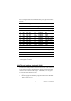
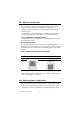
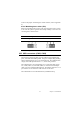

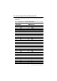


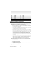
Table Of Contents
- Contents
- Chapter 1 General Information
- Chapter 2 Installation
- 2.1 Jumpers
- 2.2 Connectors
- 2.3 Locating jumpers
- 2.4 Locating Connectors
- 2.5 Setting Jumpers
- 2.6 Clear CMOS (JP4)
- 2.7 Installing DIMMs
- 2.8 IDE, CDROM hard drive connector (CN14, CN16)
- 2.9 Solid State Disk
- 2.10 Floppy drive connector (CN18)
- 2.11 Parallel port connector (CN15)
- 2.12 Keyboard and PS/2 mouse connector (CN25)
- 2.13 Power & HDD LED, Reset Button Connector (CN13, CN22)
- 2.14 Power connectors (CN27, CN5, FAN1)
- 2.15 ATX power control connector (CN3, CN23)
- 2.16 IR connector (CN24)
- 2.17 Audio interfaces (CN4, CN2)
- 2.18 COM port connector (CN19)
- 2.19 VGA/LCD/LVDS interface connections
- 2.20 TV-out interface (optional) (CN1)
- 2.21 Ethernet configuration
- 2.22 Watchdog timer configuration
- 2.23 USB connectors (CN20, CN28)
- Chapter 3 Software Configuration
- Chapter 4 Award BIOS Setup
- 4.1 System test and initialization
- 4.2 Award BIOS setup
- 4.2.1 Entering setup
- 4.2.2 Standard CMOS Features setup
- 4.2.3 Advanced BIOS Features setup
- 4.2.4 Advanced Chipset Features setup
- 4.2.5 Integrated Peripherals
- 4.2.6 Power Management Setup
- 4.2.7 PnP/PCI Configurations
- 4.2.8 PC Health Status
- 4.2.9 Frequency/Voltage Control
- 4.2.10 Load Optimized Defaults
- 4.2.11 Set Password
- 4.2.12 Save & Exit Setup
- 4.2.13 Exit Without Saving
- Chapter 5 PCI SVGA Setup
- Chpater 6 Audio Setup
- Chapter 7 PCI Bus Ethernet Interface
- Appendix A Programming the Watchdog Timer
- Appendix B Installing PC/104-Plus Modules
- Appendix C Pin Assignments
- C.1 CPU Fan Power Connector (FAN 1)
- C.2 Ethernet 10/100Base-T Connector (CN12)
- C.3 Audio Connector (CN4)
- C.4 Audio In Connector (CN2)
- C.5 Main Power Connector (CN5)
- C.6 Keyboard and PS/2 Mouse Connector (CN25)
- C.7 Floppy Disk Drive Connector (CN18)
- C.8 PC/104 plus Connectors (CN17)
- C.9 IDE Hard Drive Connector (CN14, CN16)
- C.10 Parallel Port Connector (CN15)
- C.11 Power & HDD LED Connector(CN13)
- C.12 Reset Button Connector (CN22)
- C.13 USB Connector (CN20, CN28)
- C.14 LCD Inverter Backlight Connector (CN6)
- C.15 IR Connector (CN24)
- C.16 CRT Display Connector (CN8)
- C.17 TV (video) Out Connector (CN1)
- C.18 Flat Panel Connector (CN11)
- C.19 Extended Flat Panel Display Connector (CN10)
- C.20 LCD Signal Mapping
- C.21 LVDS Connector (CN9)
- C.22 Peripheral Power Connector (CN27)
- C.23 COM Port Connector (CN19)
- C.24 CompactFlash Card Connector (CN26)
- C.25 ATX Power Feature Connector (CN3)
- Appendix D System Assignments
- Appendix E Optional Extras for the PCM-9575
- Appendix F Mechanical Drawings

PCM-9575 User’s Manual 28
3.2.2 Connections to Toshiba LTM15C151A
(1024 x 768 TFT color LCD)
28 B5 16 P7
29 GND 3 GND
30 VDD 1 +5 V
31 VDD 2 +5 V
Table 3.2: Connections to Toshiba
LTM15C151A
LTM15C151A
PCM-9575 CN11
Pin Name Pin Name
CN1-1 GND CN 11-33 GND
CN1-2 NCLK CN 11-35 LDSCLK1
CN1-3 NC
CN1-4 NC
CN1-5 GND CN 11-3 GND
CN1-6 OR0 CN 11-9 PD0
CN1-7 OR1 CN 11-11 PD2
CN1-8 OR2 CN 11-13 PD4
CN1-9 OR3 CN 11-15 PD6
CN1-10 OR4 CN 11-17 PD8
CN1-11 OR5 CN 11-19 PD10
CN1-12 GND CN 11-3 GND
CN1-13 OG0 CN 11-21 PD12
CN1-14 OG1 CN 11-23 PD14
CN1-15 OG2 CN 11-25 PD16
CN1-16 OG3 CN 11-27 PD18
CN1-17 OG4 CN 11-29 PD20
CN1-18 OG5 CN 11-31 PD22
CN1-19 GND CN 10-1 GND
CN1-20 OB0 CN 10-3 PD24
CN1-21 OB1 CN 10-5 PD26
CN1-22 OB2 CN 10-7 PD28
CN1-23 OB3 CN 10-9 PD30
CN1-24 OB4 CN 10-11 PD32
Table 3.1: Connections to Toshiba LTM10C209A