
Eden/Ezra Processor User's Manual

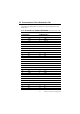


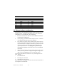
Table Of Contents
- Contents
- Chapter 1 General Information
- Chapter 2 Installation
- 2.1 Jumpers
- 2.2 Connectors
- 2.3 Locating jumpers
- 2.4 Locating Connectors
- 2.5 Setting Jumpers
- 2.6 Clear CMOS (JP4)
- 2.7 Installing DIMMs
- 2.8 IDE, CDROM hard drive connector (CN14, CN16)
- 2.9 Solid State Disk
- 2.10 Floppy drive connector (CN18)
- 2.11 Parallel port connector (CN15)
- 2.12 Keyboard and PS/2 mouse connector (CN25)
- 2.13 Power & HDD LED, Reset Button Connector (CN13, CN22)
- 2.14 Power connectors (CN27, CN5, FAN1)
- 2.15 ATX power control connector (CN3, CN23)
- 2.16 IR connector (CN24)
- 2.17 Audio interfaces (CN4, CN2)
- 2.18 COM port connector (CN19)
- 2.19 VGA/LCD/LVDS interface connections
- 2.20 TV-out interface (optional) (CN1)
- 2.21 Ethernet configuration
- 2.22 Watchdog timer configuration
- 2.23 USB connectors (CN20, CN28)
- Chapter 3 Software Configuration
- Chapter 4 Award BIOS Setup
- 4.1 System test and initialization
- 4.2 Award BIOS setup
- 4.2.1 Entering setup
- 4.2.2 Standard CMOS Features setup
- 4.2.3 Advanced BIOS Features setup
- 4.2.4 Advanced Chipset Features setup
- 4.2.5 Integrated Peripherals
- 4.2.6 Power Management Setup
- 4.2.7 PnP/PCI Configurations
- 4.2.8 PC Health Status
- 4.2.9 Frequency/Voltage Control
- 4.2.10 Load Optimized Defaults
- 4.2.11 Set Password
- 4.2.12 Save & Exit Setup
- 4.2.13 Exit Without Saving
- Chapter 5 PCI SVGA Setup
- Chpater 6 Audio Setup
- Chapter 7 PCI Bus Ethernet Interface
- Appendix A Programming the Watchdog Timer
- Appendix B Installing PC/104-Plus Modules
- Appendix C Pin Assignments
- C.1 CPU Fan Power Connector (FAN 1)
- C.2 Ethernet 10/100Base-T Connector (CN12)
- C.3 Audio Connector (CN4)
- C.4 Audio In Connector (CN2)
- C.5 Main Power Connector (CN5)
- C.6 Keyboard and PS/2 Mouse Connector (CN25)
- C.7 Floppy Disk Drive Connector (CN18)
- C.8 PC/104 plus Connectors (CN17)
- C.9 IDE Hard Drive Connector (CN14, CN16)
- C.10 Parallel Port Connector (CN15)
- C.11 Power & HDD LED Connector(CN13)
- C.12 Reset Button Connector (CN22)
- C.13 USB Connector (CN20, CN28)
- C.14 LCD Inverter Backlight Connector (CN6)
- C.15 IR Connector (CN24)
- C.16 CRT Display Connector (CN8)
- C.17 TV (video) Out Connector (CN1)
- C.18 Flat Panel Connector (CN11)
- C.19 Extended Flat Panel Display Connector (CN10)
- C.20 LCD Signal Mapping
- C.21 LVDS Connector (CN9)
- C.22 Peripheral Power Connector (CN27)
- C.23 COM Port Connector (CN19)
- C.24 CompactFlash Card Connector (CN26)
- C.25 ATX Power Feature Connector (CN3)
- Appendix D System Assignments
- Appendix E Optional Extras for the PCM-9575
- Appendix F Mechanical Drawings

27 Chapter 3 Software Configuration
3.2 Connections to Three Standard LCDs
The following tables illustrate typical LCD connection pinouts for the
PCM-9575.
3.2.1 Connections to Toshiba LTM10C209A
(640 x 480 TFT color LCD)
Table 3.1: Connections to Toshiba LTM10C209A
LTM10C209A PCM-9575 CN11
Pin Name Pin Name
1 GND 3 GND
2 CLK 35 SHFCLK
3GND 34GND
4R0 27P18
5R1 28P19
6R2 29P20
7GND 33GND
8R3 30P21
9R4 31P22
10 R5 32 P23
11 GND 34 GND
12 G0 19 P10
13 G1 20 P11
14 G2 21 P12
15 GND 8 GND
16 G3 22 P13
17 G4 23 P14
18 G5 24 P15
19 GND 8 GND
20 ENAB 37 M/DE
21 GND 4 GND
22 B0 11 P2
23 B1 12 P3
24 B2 13 P4
25 GND 4 GND
26 B3 14 P5
27 B4 15 P6