
Eden/Ezra Processor User's Manual
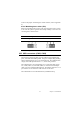


Table Of Contents
- Contents
- Chapter 1 General Information
- Chapter 2 Installation
- 2.1 Jumpers
- 2.2 Connectors
- 2.3 Locating jumpers
- 2.4 Locating Connectors
- 2.5 Setting Jumpers
- 2.6 Clear CMOS (JP4)
- 2.7 Installing DIMMs
- 2.8 IDE, CDROM hard drive connector (CN14, CN16)
- 2.9 Solid State Disk
- 2.10 Floppy drive connector (CN18)
- 2.11 Parallel port connector (CN15)
- 2.12 Keyboard and PS/2 mouse connector (CN25)
- 2.13 Power & HDD LED, Reset Button Connector (CN13, CN22)
- 2.14 Power connectors (CN27, CN5, FAN1)
- 2.15 ATX power control connector (CN3, CN23)
- 2.16 IR connector (CN24)
- 2.17 Audio interfaces (CN4, CN2)
- 2.18 COM port connector (CN19)
- 2.19 VGA/LCD/LVDS interface connections
- 2.20 TV-out interface (optional) (CN1)
- 2.21 Ethernet configuration
- 2.22 Watchdog timer configuration
- 2.23 USB connectors (CN20, CN28)
- Chapter 3 Software Configuration
- Chapter 4 Award BIOS Setup
- 4.1 System test and initialization
- 4.2 Award BIOS setup
- 4.2.1 Entering setup
- 4.2.2 Standard CMOS Features setup
- 4.2.3 Advanced BIOS Features setup
- 4.2.4 Advanced Chipset Features setup
- 4.2.5 Integrated Peripherals
- 4.2.6 Power Management Setup
- 4.2.7 PnP/PCI Configurations
- 4.2.8 PC Health Status
- 4.2.9 Frequency/Voltage Control
- 4.2.10 Load Optimized Defaults
- 4.2.11 Set Password
- 4.2.12 Save & Exit Setup
- 4.2.13 Exit Without Saving
- Chapter 5 PCI SVGA Setup
- Chpater 6 Audio Setup
- Chapter 7 PCI Bus Ethernet Interface
- Appendix A Programming the Watchdog Timer
- Appendix B Installing PC/104-Plus Modules
- Appendix C Pin Assignments
- C.1 CPU Fan Power Connector (FAN 1)
- C.2 Ethernet 10/100Base-T Connector (CN12)
- C.3 Audio Connector (CN4)
- C.4 Audio In Connector (CN2)
- C.5 Main Power Connector (CN5)
- C.6 Keyboard and PS/2 Mouse Connector (CN25)
- C.7 Floppy Disk Drive Connector (CN18)
- C.8 PC/104 plus Connectors (CN17)
- C.9 IDE Hard Drive Connector (CN14, CN16)
- C.10 Parallel Port Connector (CN15)
- C.11 Power & HDD LED Connector(CN13)
- C.12 Reset Button Connector (CN22)
- C.13 USB Connector (CN20, CN28)
- C.14 LCD Inverter Backlight Connector (CN6)
- C.15 IR Connector (CN24)
- C.16 CRT Display Connector (CN8)
- C.17 TV (video) Out Connector (CN1)
- C.18 Flat Panel Connector (CN11)
- C.19 Extended Flat Panel Display Connector (CN10)
- C.20 LCD Signal Mapping
- C.21 LVDS Connector (CN9)
- C.22 Peripheral Power Connector (CN27)
- C.23 COM Port Connector (CN19)
- C.24 CompactFlash Card Connector (CN26)
- C.25 ATX Power Feature Connector (CN3)
- Appendix D System Assignments
- Appendix E Optional Extras for the PCM-9575
- Appendix F Mechanical Drawings
PCM-9575 User’s Manual 22
2.21 Ethernet configuration
The PCM-9575 is equipped with a high performance 32-bit PCI-bus
Ethernet interface which is fully compliant with IEEE 802.3U 10/
100Mbps CSMA/CD standards. It is supported by all major network
operating systems.
The medium type can be configured via the RSET8139.EXE program
included on the utility disk. (See Chapter 3 for detailed information.)
2.21.1 100Base-T connector (CN12)
10/100Base-T connects to the PCM-9575 via an adapter cable to a 10-pin
polarized header (CN12).
2.21.2 Network boot
The Network Boot feature can be utilized by incorporating the Boot
ROM image files for the appropriate network operating system. The Boot
ROM BIOS files are included in the system BIOS, which is on the utility
CD disc.
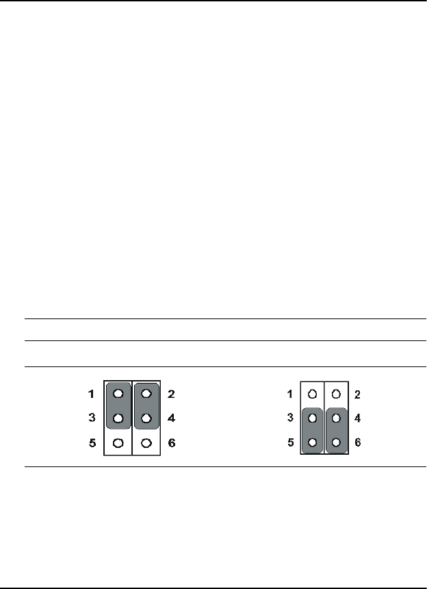
2.21.3 LAN controller power select (JP2)
Note: PCM-9575 supports Wake-on-LAN. For Wake-on LAN, J6 has to
be set to the Standby 3.3 V position
2.22 Watchdog timer configuration
An on-board watchdog timer reduces the chance of disruptions which
EMP (electro-magnetic pulse) interference can cause. This is an invalu-
able protective device for standalone or unmanned applications. Setup
Table 2.5: LAN controller power select (JP2)
3.3 V* Standby 3.3V
* default setting