
Eden/Ezra Processor User's Manual
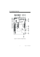
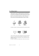
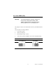
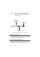
Table Of Contents
- Contents
- Chapter 1 General Information
- Chapter 2 Installation
- 2.1 Jumpers
- 2.2 Connectors
- 2.3 Locating jumpers
- 2.4 Locating Connectors
- 2.5 Setting Jumpers
- 2.6 Clear CMOS (JP4)
- 2.7 Installing DIMMs
- 2.8 IDE, CDROM hard drive connector (CN14, CN16)
- 2.9 Solid State Disk
- 2.10 Floppy drive connector (CN18)
- 2.11 Parallel port connector (CN15)
- 2.12 Keyboard and PS/2 mouse connector (CN25)
- 2.13 Power & HDD LED, Reset Button Connector (CN13, CN22)
- 2.14 Power connectors (CN27, CN5, FAN1)
- 2.15 ATX power control connector (CN3, CN23)
- 2.16 IR connector (CN24)
- 2.17 Audio interfaces (CN4, CN2)
- 2.18 COM port connector (CN19)
- 2.19 VGA/LCD/LVDS interface connections
- 2.20 TV-out interface (optional) (CN1)
- 2.21 Ethernet configuration
- 2.22 Watchdog timer configuration
- 2.23 USB connectors (CN20, CN28)
- Chapter 3 Software Configuration
- Chapter 4 Award BIOS Setup
- 4.1 System test and initialization
- 4.2 Award BIOS setup
- 4.2.1 Entering setup
- 4.2.2 Standard CMOS Features setup
- 4.2.3 Advanced BIOS Features setup
- 4.2.4 Advanced Chipset Features setup
- 4.2.5 Integrated Peripherals
- 4.2.6 Power Management Setup
- 4.2.7 PnP/PCI Configurations
- 4.2.8 PC Health Status
- 4.2.9 Frequency/Voltage Control
- 4.2.10 Load Optimized Defaults
- 4.2.11 Set Password
- 4.2.12 Save & Exit Setup
- 4.2.13 Exit Without Saving
- Chapter 5 PCI SVGA Setup
- Chpater 6 Audio Setup
- Chapter 7 PCI Bus Ethernet Interface
- Appendix A Programming the Watchdog Timer
- Appendix B Installing PC/104-Plus Modules
- Appendix C Pin Assignments
- C.1 CPU Fan Power Connector (FAN 1)
- C.2 Ethernet 10/100Base-T Connector (CN12)
- C.3 Audio Connector (CN4)
- C.4 Audio In Connector (CN2)
- C.5 Main Power Connector (CN5)
- C.6 Keyboard and PS/2 Mouse Connector (CN25)
- C.7 Floppy Disk Drive Connector (CN18)
- C.8 PC/104 plus Connectors (CN17)
- C.9 IDE Hard Drive Connector (CN14, CN16)
- C.10 Parallel Port Connector (CN15)
- C.11 Power & HDD LED Connector(CN13)
- C.12 Reset Button Connector (CN22)
- C.13 USB Connector (CN20, CN28)
- C.14 LCD Inverter Backlight Connector (CN6)
- C.15 IR Connector (CN24)
- C.16 CRT Display Connector (CN8)
- C.17 TV (video) Out Connector (CN1)
- C.18 Flat Panel Connector (CN11)
- C.19 Extended Flat Panel Display Connector (CN10)
- C.20 LCD Signal Mapping
- C.21 LVDS Connector (CN9)
- C.22 Peripheral Power Connector (CN27)
- C.23 COM Port Connector (CN19)
- C.24 CompactFlash Card Connector (CN26)
- C.25 ATX Power Feature Connector (CN3)
- Appendix D System Assignments
- Appendix E Optional Extras for the PCM-9575
- Appendix F Mechanical Drawings

PCM-9575 User’s Manual 20
2.19 VGA/LCD/LVDS interface connections
The PCM-9575’s PCI SVGA interface can drive conventional CRT dis-
plays and is capable of driving a wide range of flat panel displays, includ-
ing passive LCD and active LCD displays. The board has three
connectors to support these displays: one for standard CRT VGA moni-
tors, one for flat panel displays, and one for LVDS type LCD panels.
2.19.1 CRT display connector (CN8)
CN8 is a 16-pin, dual-inline header used for conventional CRT displays.
A simple one-to-one adapter can be used to match CN8 to a standard 15-
pin D-SUB connector commonly used for VGA.
Pin assignments for CRT display connector CN8 are detailed in Appendix
C.
2.19.2 Flat panel display connector (CN11)
CN11 consists of a 40-pin connector which can support a 24-bit LCD
panel. It is Hirose’s product no. DF13A-40DP-1.25 V
The PCM-9575 provides a bias control signal on CN11 that can be used
to control the LCD bias voltage. It is recommended that the LCD bias
voltage not be applied to the panel until the logic supply voltage (+5 V or
+3.3 V) and panel video signals are stable. Under normal operation, the
control signal (ENAVEE) is active high. When the PCM-9575’s power is
applied, the control signal is low until just after the relevant flat panel sig-
nals are present. CN11 can connect up to 24 bit TFT LCD.
2.19.3 Extension flat panel connector (CN10)
CN10 consists of a 20-pin connector which is Hirose’s product no.
DF13A-20DP-1.25V. The PCM-9575 supports a 36-bit LCD panel which
must be connected to both the CN11 (40-pin) and the CN10 (20-pin). The
pin assignments for both CN11and the CN10 can be found in Appendix C
2.19.4 LVDS LCD panel connector (CN9)
The PCM-9575 uses the VIA Twister chip that supports 2 channel (2 x
18 bit) LVDS LCD panel displays. Users can connect to either an 18-bit
or 36-bit LVDS LCD with CN9.
2.19.5 Panel type selection (S1)