
Eden/Ezra Processor User's Manual
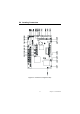
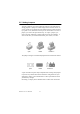
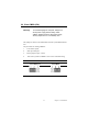
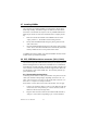
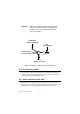
Table Of Contents
- Contents
- Chapter 1 General Information
- Chapter 2 Installation
- 2.1 Jumpers
- 2.2 Connectors
- 2.3 Locating jumpers
- 2.4 Locating Connectors
- 2.5 Setting Jumpers
- 2.6 Clear CMOS (JP4)
- 2.7 Installing DIMMs
- 2.8 IDE, CDROM hard drive connector (CN14, CN16)
- 2.9 Solid State Disk
- 2.10 Floppy drive connector (CN18)
- 2.11 Parallel port connector (CN15)
- 2.12 Keyboard and PS/2 mouse connector (CN25)
- 2.13 Power & HDD LED, Reset Button Connector (CN13, CN22)
- 2.14 Power connectors (CN27, CN5, FAN1)
- 2.15 ATX power control connector (CN3, CN23)
- 2.16 IR connector (CN24)
- 2.17 Audio interfaces (CN4, CN2)
- 2.18 COM port connector (CN19)
- 2.19 VGA/LCD/LVDS interface connections
- 2.20 TV-out interface (optional) (CN1)
- 2.21 Ethernet configuration
- 2.22 Watchdog timer configuration
- 2.23 USB connectors (CN20, CN28)
- Chapter 3 Software Configuration
- Chapter 4 Award BIOS Setup
- 4.1 System test and initialization
- 4.2 Award BIOS setup
- 4.2.1 Entering setup
- 4.2.2 Standard CMOS Features setup
- 4.2.3 Advanced BIOS Features setup
- 4.2.4 Advanced Chipset Features setup
- 4.2.5 Integrated Peripherals
- 4.2.6 Power Management Setup
- 4.2.7 PnP/PCI Configurations
- 4.2.8 PC Health Status
- 4.2.9 Frequency/Voltage Control
- 4.2.10 Load Optimized Defaults
- 4.2.11 Set Password
- 4.2.12 Save & Exit Setup
- 4.2.13 Exit Without Saving
- Chapter 5 PCI SVGA Setup
- Chpater 6 Audio Setup
- Chapter 7 PCI Bus Ethernet Interface
- Appendix A Programming the Watchdog Timer
- Appendix B Installing PC/104-Plus Modules
- Appendix C Pin Assignments
- C.1 CPU Fan Power Connector (FAN 1)
- C.2 Ethernet 10/100Base-T Connector (CN12)
- C.3 Audio Connector (CN4)
- C.4 Audio In Connector (CN2)
- C.5 Main Power Connector (CN5)
- C.6 Keyboard and PS/2 Mouse Connector (CN25)
- C.7 Floppy Disk Drive Connector (CN18)
- C.8 PC/104 plus Connectors (CN17)
- C.9 IDE Hard Drive Connector (CN14, CN16)
- C.10 Parallel Port Connector (CN15)
- C.11 Power & HDD LED Connector(CN13)
- C.12 Reset Button Connector (CN22)
- C.13 USB Connector (CN20, CN28)
- C.14 LCD Inverter Backlight Connector (CN6)
- C.15 IR Connector (CN24)
- C.16 CRT Display Connector (CN8)
- C.17 TV (video) Out Connector (CN1)
- C.18 Flat Panel Connector (CN11)
- C.19 Extended Flat Panel Display Connector (CN10)
- C.20 LCD Signal Mapping
- C.21 LVDS Connector (CN9)
- C.22 Peripheral Power Connector (CN27)
- C.23 COM Port Connector (CN19)
- C.24 CompactFlash Card Connector (CN26)
- C.25 ATX Power Feature Connector (CN3)
- Appendix D System Assignments
- Appendix E Optional Extras for the PCM-9575
- Appendix F Mechanical Drawings

PCM-9575 User’s Manual 14
2.7 Installing DIMMs
The procedure for installing DIMMs is described below. Please follow
these steps carefully. The number of pins are different on either side of
the breaks, so the module can only fit in one way. DIMM modules have
different pin contacts on each side, and therefore have a higher pin den-
sity.
1. Make sure that the two handles of the DIMM socket are in the
“open” position. i.e. The handles remain leaning outward.
2. Slowly slide the DIMM module along the plastic guides on both
ends of the socket.
3. Press the DIMM module right down into the socket, until you hear
a click. This is when the two handles have automatically locked the
memory module into the correct position of the socket.
To remove the memory module, just push both handles outward, and the
module will be ejected from the socket.
2.8 IDE, CDROM hard drive connector (CN14, CN16)
The PCM-9575 provides 2 IDE channels which you can attach up to four
Enhanced Integrated Device Electronics hard disk drives or CDROM to
the PCM-9575’s internal controller. The PCM-9575's IDE controller uses
a PCI interface. This advanced IDE controller supports faster data trans-
fer, PID mode 3, mode 4 and UDMA/100. The secondary channel sup-
ports UDMA/33 only.
2.8.1 Connecting the hard drive
Connecting drives is done in a daisy-chain fashion. It requires one of two
cables (not included in this package), depending on the drive size. 1.8"
and 2.5" drives need a 1 x 44-pin to 2 x 44-pin flat-cable connector. 3.5"
drives use a 1 x 44-pin to 2 x 40-pin connector.
Wire number 1 on the cable is red or blue, and the other wires are gray.
1. Connect one end of the cable to CN14 or CN16. Make sure that the
red (or blue) wire corresponds to pin 1 on the connector, which is
labeled on the board (on the right side).
2. Plug the other end of the cable into the Enhanced IDE hard drive,
with pin 1 on the cable corresponding to pin 1 on the hard drive.