Remote Supervisor Adapter User’s Guide
Remote Supervisor Adapter User’s Guide
Note: Before using this information and the product it supports, be sure to read the general information in Appendix B, “Notices” on page 109. Sixth Edition (October 2002) © Copyright International Business Machines Corporation 2001, 2002. All rights reserved. US Government Users Restricted Rights – Use, duplication or disclosure restricted by GSA ADP Schedule Contract with IBM Corp.
Contents Chapter 1. Introduction . . . . . Remote Supervisor Adapter features Web browser requirements . . . . Notices used in this book . . . . . . . . . . . . . . . . . . . . . . . . . . . . . . . . . . . . . . . . . . . . . . . . . . . . . . . . . . . . . . . . . . . . . . . . 1 1 2 2 Chapter 2. Opening and using the ASM Web interface . . . . . Logging in to the Remote Supervisor Adapter . . . . . . . . . . Logging in to the ASM processor in an xSeries 330 server . . . . .
Accessing remote adapters through an ASM interconnect network . . . . . . 62 Chapter 6. Starting and configuring the ASM text-based interface Accessing the text-based interface through a Telnet connection . . . Accessing the text-based interface through a direct serial connection . Configuring terminal settings . . . . . . . . . . . . . . . . Accessing remote adapters through an ASM interconnect network . . . . . . . . . . . . . . . . . . . . . . 65 65 66 66 67 Chapter 7.
Chapter 1. Introduction This manual explains how to use the functions of the IBM® Remote Supervisor Adapter when you install it in an IBM Eserver xSeries™ server. The IBM Remote Supervisor Adapter is one of the products in the Advanced System Management (ASM) family.
Web browser requirements The Remote Supervisor Adapter supports the following Web browsers for remote access. The Web browser that you use must be Java™-enabled and must support JavaScript™ 1.2 or later. v Microsoft® Internet Explorer version 4.0 (with Service Pack 1), or later v Netscape Navigator version 4.72, or later (version 6.x is not supported) Notes: 1. Java plug-in version 1.4 or later is required for the remote start (boot) feature, which is not available on all servers. 2.
Chapter 2. Opening and using the ASM Web interface To access the Remote Supervisor Adapter remotely using the ASM Web interface, you must log in to the adapter. This chapter describes the login procedures and describes the actions you can perform from the ASM Web interface. For an xSeries 330 server: Certain features of the ASM Web interface and text-based interface are available only through the ASM processor that is integrated on the system board of an xSeries 330 server.
configuration for enhanced security. 3. Select a timeout value from the drop-down list in the field provided. If your browser is inactive for that number of minutes, the Remote Supervisor Adapter logs you off the ASM Web interface. 4. Click Continue to start the session. The window that opens depends on the type of server in which the Remote Supervisor Adapter is installed.
gives you a quick view of the server status. For descriptions of the actions that you can perform from the links in the left navigation pane of the ASM Web interface, see “Remote Supervisor Adapter and ASM processor action descriptions” on page 7. Then, go to Chapter 3, “Configuring your Remote Supervisor Adapter or ASM processor” on page 13.
Logging in to the ASM processor in an xSeries 330 server The integrated ASM processor on the system board of an xSeries 330 server enables you to monitor the health of the managed server, view the server event log and vital product data, configure alerts and alert recipients, and perform power and restart operations on the server.
Note: The ASM processor is set initially with a user name of USERID and password of PASSW0RD (with a zero, not an O). This user has read/write access. Change this default password during your initial configuration for enhanced security. 5. The System Health page for the monitored server is displayed.
Table 1. Actions available when logged in to a Remote Supervisor Adapter or when logged in to the ASM processor in an xSeries 330 server (continued) Link Action Description Power/Restart Remotely power on or restart a server The Remote Supervisor Adapter or ASM processor provides full remote power control over your server with power-on, power-off, and restart actions. In addition, power-on and restart statistics are captured and displayed to show server hardware availability.
Table 1. Actions available when logged in to a Remote Supervisor Adapter or when logged in to the ASM processor in an xSeries 330 server (continued) Link Action Description Network Interfaces Configure the network interfaces You can configure network-access settings to the Remote of the Remote Supervisor Adapter Supervisor Adapter from the Network Interfaces page, which is available only when you log in to the Remote Supervisor Adapter.
names used by the ASM Web interface are identical; however, the information and functions that are supported differ. In the following table, these features are explained as they function when you are logged in to the Remote Supervisor Adapter and not the ASM processor. Table 2.
Table 2. Actions available when logged in to the Remote Supervisor Adapter installed in an xSeries 330 server (continued) Link Action Description Configuration File Back up and restore the Remote Supervisor Adapter configuration You can back up, modify, and restore the configuration of the Remote Supervisor Adapter from the Configuration File window.
12 Remote Supervisor Adapter: User’s Guide
Chapter 3. Configuring your Remote Supervisor Adapter or ASM processor Use the links under ASM Control in the navigation pane to configure the Remote Supervisor Adapter or the ASM processor in an xSeries 330 server. The features available to you depend on whether you are logged in to a Remote Supervisor Adapter, the server type in which the Remote Supervisor Adapter is installed, or whether you are logged in to an ASM processor.
Setting system information Complete the following steps to set your Remote Supervisor Adapter system information: 1. Log in to the Remote Supervisor Adapter where you want to set the system information. For more information, see Chapter 2, “Opening and using the ASM Web interface” on page 3. For an xSeries 330 server: To set the system information for the ASM processor, log in to the ASM processor. For more information, see “Logging in to the ASM processor in an xSeries 330 server” on page 6. 2.
4. In the ID number field, assign the Remote Supervisor Adapter a unique identification number. 5. In the Contact field, type the contact information. For example, you can specify the name and phone number of the person to contact if there is a problem with this server. You can type a maximum of 47 characters in this field. Note: The Contact field is not available for all servers. 6. In the Location field, type the location of the server.
POST watchdog Use the POST watchdog field to specify the number of minutes that the Remote Supervisor Adapter or ASM processor will wait for this server to complete a power-on self-test (POST). If the server being monitored fails to complete a POST within the specified time, the Remote Supervisor Adapter generates a POST timeout alert and automatically restarts the server.
interval is exceeded, the Remote Supervisor Adapter or ASM processor generates a loader timeout alert and automatically restarts the system. After the system is restarted, the loader timeout is automatically disabled until the operating system is shut down and the server is power cycled (or until the operating system starts and the device driver successfully loads).
interrupt usually indicates a critical error such as a hardware fault. A nonmaskable interrupt usually signals a parity error in the memory subsystem. To disable the automatic server restart after a nonmaskable interrupt, select Disabled. Note: The NMI reset delay field is not available on all servers. 5. Scroll to the bottom of the page and click Save.
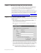
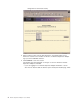
similar to the one in the following illustration opens. 5. In the Date field, type the numbers of the current month, day, and year in the matching entry fields. 6. In the Time field, type the numbers corresponding to the current hour, minutes, and seconds in the appropriate entry fields. The hour (hh) must be a number from 00 to 23 as represented on a 24-hour clock. The minutes (mm) and seconds (ss) must be numbers from 00 to 59. 7.
following illustration opens. 4. Click one of the unused login profile links. An individual profile window similar to the one in the following illustration opens. 5. In the Login ID field, type the name of the profile. You can type a maximum of 15 characters in the Login ID field. Valid characters are uppercase and lowercase letters, numbers, periods, and underscores. Note: This login ID is used to grant remote access to the Remote Supervisor Adapter or ASM processor.
6. In the Authority level field, select either Read Only or Read/Write to set the access rights for this login ID. Read Only The user can use the Read Only option to view a window, but not to make changes. Additionally, users who log in with read-only IDs are unable to perform file transfers, power and restart actions, or remote control functions.
5. To allow remote users to dial in to the Remote Supervisor Adapter or ASM processor through a serial connection, select Enabled in the Logins through a modem connection field. 6. In the Lockout period after five login failures field, specify how long, in minutes, the Remote Supervisor Adapter or ASM processor will prohibit remote login attempts, if more than five sequential failures to log in remotely are detected.
2. For an xSeries 330 server: If you want to configure a remote alert recipient on the ASM processor, log in to the ASM processor. For more information, see “Logging in to the ASM processor in an xSeries 330 server” on page 6. 3. In the navigation pane, click Alerts. The Remote Alert Recipients page opens. You can see the notification method and alert status, if set, for each recipient. 4. Click one of the remote alert recipient links.
Notes: a. To configure a remote alert recipient for IBM Director over Modem or IBM Director over LAN, the remote alert recipient must be a server with the Director Management Server installed. b. The IBM Director over Modem option is supported in only IBM Director versions 2.2.1, 3.1, and 3.1.1. 9. In the Number field, type either the phone number, IP address, or host name at which to reach the recipient.
Note: All selected alert events are sent to all configured remote alert recipients. Forwarding alerts The Alert Forwarding setting applies only to alerts forwarded from the integrated system management processor (ISMP) on an ASM interconnect network. The ISMPs on the network forward alerts to only the Remote Supervisor Adapter that is designated as the gateway. A Remote Supervisor Adapter is a gateway to the interconnect network if: v On the Alerts Forwarding page, you click Make this ASM the Gateway.
Complete the following steps to set the number of times the Remote Supervisor Adapter or ASM processor attempts to send an alert: 1. Log in to the Remote Supervisor Adapter on which you want to set remote alert attempts. For more information, see Chapter 2, “Opening and using the ASM Web interface” on page 3. 2. For an xSeries 330 server: If you want to set the remote alert attempts on the ASM processor, log in to the ASM processor.
2. For an xSeries 330 server: To set the remote alert attempts on the ASM processor, log in to the ASM processor. For more information, see “Remote Supervisor Adapter and ASM processor action descriptions” on page 7. 3. In the navigation pane, click Alerts and scroll down to the Monitored Alerts section. 4. Select the events you want the Remote Supervisor Adapter or ASM processor to monitor.
Table 4. Warning remote alerts Alphanumeric pager code Event Action 10 Redundant power supply failure Generates an alert if a redundant power supply fails. 11 Single fan failure Generates an alert if one fan fails. 12 Temperature irregularity Generates an alert if any monitored temperatures are outside the warning threshold values. To access these temperature threshold values, click the temperature readings on the System Health page.
Setting local events Complete the following steps to select the local events to which the Remote Supervisor Adapter or ASM processor will respond: 1. Log in to the Remote Supervisor Adapter where you want to set local events. For more information, see Chapter 2, “Opening and using the ASM Web interface” on page 3. 2. For an xSeries 330 server: Log in to the ASM processor. For more information, see “Remote Supervisor Adapter and ASM processor action descriptions” on page 7. 3.
able to monitor the serial port in the operating system or in any other applications. This design enables a single serial port to conduct normal functions and also maintain out-of-band alerting capabilities. Notes for an xSeries 330 server: 1. The ASM processor on an xSeries 330 server uses the two serial ports on the rear of your server. One of these serial ports can be shared with the server operating system while the other is dedicated to the ASM processor. 2.
If you are logged in to the ASM processor, a window similar to the one in the following illustration opens. Note: Only Serial Port 1 appears on the Serial Port page when you are logged in to the Remote Supervisor Adapter. 4. In the Baud rate field, select the data-transfer rate. Use the Baud rate field to specify the data-transfer rate of your serial port connection. To set the baud rate, select the data-transfer rate, in bits per second, that corresponds to your serial port connection. 5.
8. If you are logged in to an ASM processor: Select the Dedicate to ASM check box to reserve serial port 1 for the ASM processor. This option is displayed only when you are logged in to an ASM processor. If shared with the operating system, the serial port serves the ASM processor only when the server is turned off or during the power-on self-test (POST). The operating system can access it after the POST is completed.
Table 7. Port 1 settings (continued) Field What you type Hangup string Type the initialization string that will be used to instruct the modem to disconnect. A default string is provided (ATH0). Do not change this string unless your dial-out functions are not working properly. Dial postfix string Type the initialization string that is used after the number is dialed to tell the modem to stop dialing. The default is ^M.
Configuring network interfaces On the Network Interfaces page, you can set access to the Remote Supervisor Adapter by: v Configuring an Ethernet connection to a Remote Supervisor Adapter v Configuring point-to-point protocol access over a serial port Configuring an Ethernet connection to the Remote Supervisor Adapter Complete the following steps to configure the Ethernet setup for the Remote Supervisor Adapter: 1. Log in to the Remote Supervisor Adapter where you want to setup the configuration.
You can enter a maximum of 63 characters in this field, which represents the IP host name of the Remote Supervisor Adapter. The host name defaults to ASMA followed by the Remote Supervisor Adapter burned-in media access control (MAC) address.
The following table describes the functions on the Advanced Ethernet page. Table 8. Advanced Ethernet setup Field Function Data rate Use the Data Rate field to specify the amount of data to be transferred per second over your LAN connection. To set the data rate, click the menu and select the data-transfer rate in Mb1 that corresponds to the capability of your network. To automatically detect the data-transfer rate, select Auto, which is the default value.
Note: If you enable the PPP interface, the Remote Supervisor Adapter cannot use the serial port for serial remote access. Complete the following steps to configure PPP access over a serial port: 1. Log in to the Remote Supervisor Adapter where you want to configure PPP access over a serial port. For more information, see Chapter 2, “Opening and using the ASM Web interface” on page 3. 2. In the navigation pane, click Network Interfaces. Scroll down to the PPP over Serial Port section.
v The CHAP Only setting uses a three-way handshake procedure to validate the identity of the originator of a connection upon connection at any time later. The challenge handshake authentication protocol (CHAP) is stronger than the PAP protocol and protects against playback and trial-and-error attacks. v The CHAP then PAP setting tries to authenticate using CHAP first. If the originator of the connection does not support CHAP, then PAP is tried as a secondary authentication protocol.
4. In the navigation pane, click Network Protocols. A window similar to the one in the following illustration opens. 5. Select Enabled in the SNMP agent and SNMP traps fields to forward alerts to SNMP communities on your network. To enable the SNMP agent, the following criteria must be met: v System contacts must be specified on the System Settings page. For information about the System Settings page settings, see “Setting system information” on page 14.
page and click Save to save your corrected information. You must configure at least one community to enable this SNMP agent. 7. In the Community Name field, enter a name or authentication string to specify the community. 8. In the corresponding Host Name or IP Address field, enter the host name or IP addresses of each community manager. 9. If a DNS server is not available on your network, scroll to the bottom of the page and click Save. 10.
13. Scroll to the bottom of the page and click Save. 14. In the navigation pane, click Restart ASM to activate the changes. Configuring SMTP Complete the following steps to specify the IP address or host name of the Simple Mail Transfer Protocol (SMTP) server: 1. Log in to the Remote Supervisor Adapter where you want to configure the SMTP. For more information, see Chapter 2, “Opening and using the ASM Web interface” on page 3. 2.
Using the configuration file When logged in to the Remote Supervisor Adapter, select Configuration File in the navigation pane to: v Back up the ASM configuration v Restore the ASM configuration Backing up your current configuration You can download a copy of your current ASM configuration to the computer that is running the ASM Web interface. Use this backup copy to restore your Remote Supervisor Adapter configuration if it is accidentally changed or damaged.
Restoring and modifying your ASM configuration You can restore a saved configuration in full or you can modify key fields in the saved configuration before restoring the configuration to your Remote Supervisor Adapter. Modifying the configuration file before restoring it helps you set up multiple Remote Supervisor Adapters with similar configurations. You can quickly specify parameters that require unique values such as names and IP addresses, without having to enter common, shared information.
Attention: When you click Restore Defaults, you will lose all the modifications you made to the Remote Supervisor Adapter, ASM processor, or ASM PCI adapter. You also lose the remote control of the remote servers. If you click Restore Defaults, you will have to reset the remote control password locally on the remote server in the BIOS setup menu (accessed by pressing F1 in POST). Complete the following steps to restore the ASM defaults: 1. Log in to the Remote Supervisor Adapter.
Chapter 4. Monitoring remote server status Use the links under the Monitors heading of the navigation pane to view the status of the server you are accessing.
following illustration opens. The status of your server determines the message shown at the top of the System Health Summary page.
When you click a temperature reading, a window similar to the one in the following illustration opens. The Temperature Thresholds page displays the temperature levels at which the Remote Supervisor Adapter or ASM processor reacts. The temperature threshold values are preset on the remote server and cannot be changed.
Note: The hard shutdown alert is sent only if a soft shutdown alert has not yet been sent. 5. Scroll down to the voltages section. The Remote Supervisor Adapter or ASM processor will send an alert if any monitored power source voltage falls outside its specified operational ranges. If you click a voltage reading, a window similar to the one in the following illustration opens. The Voltage Thresholds page displays the voltage ranges at which the Remote Supervisor Adapter or ASM processor reacts.
the server immediately shuts down and sends an alert to configured remote alert recipients. You must select the Voltage check box on the Alerts page for the alert to be sent. Note: The hard shutdown alert is sent only if a soft shutdown alert has not yet been sent. 6. Scroll down to the Fan Speeds section. The ASM Web interface displays the running speed of the server fans (expressed in a percentage of the maximum fan speed).
3. In the navigation pane, click Event Log to view the recent history of events on the server. A window similar to the one in the following illustration opens. 4. Scroll down to view the complete contents of the event log. The events are given the following levels of severity: Informational This severity level is assigned to an event of which you should take note. Warning This severity level is assigned to an event that could affect server performance.
Viewing vital product data Upon server startup, the Remote Supervisor Adapter or ASM processor collects system, basic input/output (BIOS) information, and server component vital product data (VPD) and stores it in nonvolatile memory. You can access this information at any time from almost any computer. The Vital Product Data page contains key information about the remote managed server that the Remote Supervisor Adapter is monitoring.
Component Activity Log You can find a record of component activity in this section. Table 11. Component activity log Field Function FRU number Identifies the field replaceable unit (FRU) number (a seven-digit alphanumeric identifier) of the component. Serial number Identifies the serial number of the component. Manufacturer ID Identifies the manufacturer of the component. Slot Identifies the slot number where the component is located. Action Identifies the action taken by each component.
Table 14. ASM vital product data Field Function Firmware type Identifies the ASM firmware component type: main application, boot ROM, or remote control. Build ID Identifies the build IDs and vital product data of the application firmware and the startup ROM firmware. File name Identifies the file names and vital product data of the application firmware and the startup ROM firmware.
54 Remote Supervisor Adapter: User’s Guide
Chapter 5. Performing Remote Supervisor Adapter tasks Use the functions under the Tasks heading in the navigation pane to directly control the actions of the Remote Supervisor Adapter and your server. The tasks you can perform depend on the server in which the Remote Supervisor Adapter is installed.
Server power and restart activity The Server Power and Restart Activity section displays the power status of the server when the Web page was generated. Power The Power field shows the power status of the server at the time this Web page was generated. State The State field shows the state of the server when this Web page was generated.
Remotely controlling the power status of a server The Remote Supervisor Adapter provides full remote power control over your server with power on, power off, and restart actions. In addition, power-on and restart statistics are captured and displayed to show server hardware availability. Attention: Read the following information to prevent the loss of data or damage to data when you perform a remote shutdown of your operating system: 1.
Remote Supervisor Adapter device driver is installed. You might also need to install IBM Director Agent. For more information, see the Attention notice at the beginning of this section. Shutdown O/S and then restart server To restart the operating system, click Shutdown O/S and then Restart Server. This option requires that the Remote Supervisor Adapter device driver is installed. You might also need to install IBM Director Agent.
2. 3. 4. 5. In the navigation pane, click Remote Boot. Click Remote Booting From a Diskette Image. Select the diskette image file. Click Boot Server. After the file transfer is complete, a confirmation window opens. 6. Click Continue in the confirmation window to start the server using the transferred image.
3. Click Redirect Server Console. A Java applet opens in a separate browser window. 4. In the Password field, enter the remote control password. This password is configured locally on the server in the BIOS setup menu (accessed by pressing F1 in POST). For more information about the remote control password, refer to the Remote Supervisor Adapter Installation Guide. The server desktop opens on your screen.
Note: The Windows blue screen capture is available only if the Microsoft Windows NT or Windows 2000 operating system is installed. Complete the following steps to remotely access a server blue-screen image: 1. Log in to the Remote Supervisor Adapter. For more information, see Chapter 2, “Opening and using the ASM Web interface” on page 3. 2. In the navigation pane, click System Settings; then, select the appropriate timeout value from the drop-down menu to enable the OS watchdog option. 3.
13. To log in to the Remote Supervisor Adapter again, open your browser and follow your regular login process. Note: To cancel this process, click Cancel. Accessing remote adapters through an ASM interconnect network You can connect to remote systems through the ASM interconnect network from the Access Remote ASM link. The Remote ASM Access table displays color-coded icons to indicate the overall status of each remote system in the System Health column.
Direct LAN Connection Click the IP address link to bypass the ASM interconnect connection and to connect to a remote system directly through your Ethernet network. This connection offers faster access to a remote ASM. To directly log in to a remote system displayed in the table, click the IP address link corresponding to the remote system that you want to access. Then, follow the standard login procedure to gain access to that remote system.
64 Remote Supervisor Adapter: User’s Guide
Chapter 6. Starting and configuring the ASM text-based interface You can establish a Telnet connection or a direct serial connection to remotely access the Remote Supervisor Adapter or the ASM processor on an xSeries 330 server through the text-based user interface. This chapter describes the login procedure and how to configure the text-based interface. Note: F1 through F4 are the only function keys that are supported in the text-based interface.
Use the following keys to navigate through the windows in the text-based interface: v Press the Up Arrow and Down Arrow keys ( ↑ and ↓ ) to navigate the Advanced System Management window. v Press Esc to exit to the Advanced System Management window. v Press Esc at the Advanced System Management window to log off from your session. v Press F3 to exit the window you are viewing. v Press F4 or press Enter to save your changes.
1. Select Terminal → Preferences. The Terminal Preferences window opens. 2. Select the following check box options: v Blinking Cursor or Block Cursor v VT100 Arrows v VT-100/ANSI 3. Click Fonts. The Font window opens. 4. In the Font field, select Terminal. In the Size field, select 9. 5. Click OK. Accessing remote adapters through an ASM interconnect network You can access remote systems through the ASM interconnect network from the Remote ASM Access window. Each remote system is listed. Chapter 6.
Complete the following steps to remotely access Remote Supervisor Adapters or ASM processors on the ASM interconnect network: 1. If you have not already done so, start a Telnet session or establish a direct serial connection. 2. Log in to the Remote Supervisor Adapter. For more information, see “Accessing the text-based interface through a Telnet connection” on page 65. 3. In the Advanced System Management window, select Remote ASM Access.
Chapter 7. Configuring your Remote Supervisor Adapter using a text-based interface In the Advanced System Management window, use the Settings options under the Setup heading to configure your Remote Supervisor Adapter values. The monitoring features available to you depend on whether you are logged in to the Remote Supervisor Adapter or the ASM processor on an xSeries 330 server. Note: F1 through F4 are the only function keys that are supported in the text-based interface.
3. In the Advanced System Management window, select Settings. The Settings window opens. 4. In the Settings window, select System. A window similar to the one in the following illustration opens. ASMDEMO ASMDEMO Note: Depending on whether you are logged in to the Remote Supervisor Adapter or ASM processor, some options are not available. 5. In the ASM Name field, type the name of the Remote Supervisor Adapter. Use the ASM Name field to specify a name for the ASM in this server.
Setting server timeouts Complete the following steps to set your server timeout values: 1. Log in to the Remote Supervisor Adapter. For more information, see “Accessing the text-based interface through a Telnet connection” on page 65 or “Accessing the text-based interface through a direct serial connection” on page 66. 2. For an xSeries 330 server: Log in to the ASM processor. For more information, see “Accessing remote adapters through an ASM interconnect network” on page 67. 3.
constructed POST routine available only on specific IBM servers. If this routine does not exist on your server, all settings in this field are ignored. For more information about POST routines, see the documentation that comes with your server. Loader Watchdog Use the Loader Watchdog field to specify the number of minutes that the Remote Supervisor Adapter or ASM processor waits between the completion of POST and the starting of the operating system.
Power Off Delay Attention: Read the following information to prevent the loss of data or damage to data when you perform a remote shutdown of your operating system: a. If the Windows 2000, Windows NT, Red Hat Linux, or SuSE Linux operating system is installed on your server, you need to install only the Remote Supervisor Adapter device driver to support remote operating system shutdown.
1. Log in to the Remote Supervisor Adapter. For more information, see “Accessing the text-based interface through a Telnet connection” on page 65 or “Accessing the text-based interface through a direct serial connection” on page 66. 2. For an xSeries 330 server: Log in to the ASM processor. For more information, see “Accessing remote adapters through an ASM interconnect network” on page 67. 3. In the Advanced System Management window, select Settings. The Settings window opens. 4.
5. In the Login & Alert Profiles window, select Login Profiles. A window similar to the one in the following illustration opens. Use the Login Profiles window to view, configure, or change individual login profiles. You can define up to 12 unique profiles. If you have not configured a profile, the name of the profile by default is User nn where nn is an arbitrary number assigned to that profile. 6. Select a profile name. A window similar to the one in the following illustration opens. 7.
Read-Only Enables the user to view a window but not to make changes. Additionally, users who log in with read-only IDs are unable to perform file transfers, power and restart actions, or remote control functions. Read/Write Enables the user to take all available actions provided by the interface, including setting up a user ID and turning off the server. 10.
5. In the Login & Alert Profiles window, select Login Settings. A window similar to the one in the following illustration opens. 6. In the Dial-in Support Status field, select Enabled to enable remote users to dial in to the Remote Supervisor Adapter or ASM processor through a serial connection. 7.
3. In the Advanced System Management window, select Settings. The Settings window opens. 4. In the Settings window, select Login & Alert Profiles. 5. In the Login & Alert Profiles window, select Remote Alert Recipients. A window similar to the following opens. 6. Select a remote alert recipient option. An individual recipient window similar to the one in the following illustration opens. ASMDEMO 7. In the Name field, type the name of the recipient or the transmission method.
v IBM Director over modem v SNMP over PPP v E-mail over PPP Type an IP address or host name if you are using the IBM Director over LAN method. 9. In the Status field, select Enabled to activate this remote alert recipient. 10. Select Enabled in the Receive critical alerts only field if you want the recipient to receive only critical alerts. 11. Select the notification method for reaching the recipient in the Notification Method field.
Note: For the E-mail over LAN and E-mail over PPP notification methods to work properly, configure the SMTP options on the Network Interfaces/Protocols window. For more information about SMTP, see “Configuring SMTP” on page 94. 16. Press F4 or press Enter to apply your changes. 17. Press F3 twice to return to the Login & Alert Profiles window. Setting remote alert attempts Complete the following steps to set the number of times the Remote Supervisor Adapter attempts to send an alert: 1.
10. Press F3 to return to the Login & Alert Profiles window. Setting remote alerts Complete the following steps to select which remote alerts are to be sent by the Remote Supervisor Adapter: 1. Log in to the Remote Supervisor Adapter. For more information, see “Accessing the text-based interface through a Telnet connection” on page 65 or “Accessing the text-based interface through a direct serial connection” on page 66. 2. For an xSeries 330 server: Log in to the ASM processor.
Critical alerts Critical alerts are generated for events that signal that the server is no longer functioning. Table 18. Critical remote alerts Alphanumeric pager code Event Action 00 Temperature irregularity Generates an alert if any of the monitored temperatures are outside critical threshold values. Select Temperature Tables in the Temperature, Voltage and Fan window to view the threshold values. If a critical temperature condition is detected, the server automatically shuts down and turns off.
6. Press F3 and select System Remote Alerts. System alerts System alerts are generated for events that occur as a result of system errors. Table 20. System remote alerts Alphanumeric pager code Event Action 20 POST timeout Generates an alert if an enabled POST timeout value is exceeded. The POST timeout value is configured in the Server Timeouts section in the System window. 21 O/S timeout Generates an alert if an enabled operating system timeout value is exceeded.
Table 21. Local events (continued) Event Action Fan failure Generates a local notification if one or more cooling fans fails. Power supply failure Generates a local notification if a power supply failure is detected. DASD failure Generates a local notification if a hard disk drive failure is detected. PFA Generates a local notification if the hardware in the server generates a PFA event. 9. Press F4 or press Enter to apply your changes.
4. In the Settings window, select Serial Port 1. A window similar to the one in the following illustration opens. ASMDEMO 5. In the Baud Rate field, select a data-transfer rate. The baud rate specifies the data-transfer rate of your serial port connection. To set the baud rate, select the data-transfer rate, in bits per second, that corresponds to your serial port connection. 6. In the Parity field, select the error detection to use in your serial connection. 7.
Table 22. Port 1 settings Field What you enter Initialization string Type the initialization string that will be used for the specified modem. A default string is provided (ATE0). Do not change this string unless your dial-out functions are not working properly. Caller ID string Type the initialization string that will be used to get caller ID information from the modem. Factory settings string Type the initialization string that returns the modem to its factory settings when the modem is initialized.
MNP RTS microcom networking protocol ready to send Configuring network interfaces With the network interface options, you can set access to the Remote Supervisor Adapter by: v Configuring an Ethernet connection to a Remote Supervisor Adapter v Configuring point-to-point protocol access over a serial port Configuring an Ethernet connection to the Remote Supervisor Adapter Complete the following steps to configure your Ethernet setup: 1. Log in to the Remote Supervisor Adapter.
Note: The values in the following window are examples. Your settings will be different. ASMDEMO Server 1 5. In the Interface field, select Enabled. It is enabled by default. 6. If you want to use a dynamic host configuration protocol (DHCP) server connection, select Enable in the DHCP field; then, go to step 11. Note: Do not select Enable in the DHCP field unless you have an accessible, active, and configured DHCP server on your network.
v No spaces or consecutive periods 10. In the Subnet Mask field, type the subnet mask used by the Remote Supervisor Adapter. This step is necessary only if you disabled DHCP. The subnet mask must contain: v Four integers from 0 through 255 separated by periods v No spaces or consecutive periods The default setting is 255.255.255.0. 11. Select Advanced Ethernet Settings if you need to set additional Ethernet settings. Make modifications as necessary. ASMDEMO Table 23.
If DHCP is enabled, the host name, IP address, gateway address, subnet mask, and DNS server IP address are set automatically. 14. Press F3 until you reach the Network Interfaces/Protocols window and then select Restart ASM. Configuring PPP access over the serial port Use the point-to-point protocol (PPP) access method if you do not have Ethernet access. You can use PPP through your serial port to enable access to the Remote Supervisor Adapter through a Telnet session or a Web browser.
7. In the Remote IP Address field, enter the remote IP address that this Remote Supervisor Adapter will assign to a remote user. The field defaults to 192.96.1.2. The remote IP address must contain: v Four integers from 0 through 255 separated by periods v No spaces 8. In the Subnet Mask field, enter the subnet mask that will be used by the Remote Supervisor Adapter. The default is 255.255.255.255. The subnet mask must contain: v Four integers from 0 through 255 separated by periods v No spaces 9.
1. Log in to the Remote Supervisor Adapter. For more information, see “Accessing the text-based interface through a Telnet connection” on page 65 or “Accessing the text-based interface through a direct serial connection” on page 66. 2. In the Advanced System Management window, select Settings. The Settings window opens. 3. In the Settings window, select System and enter your system contact and system location information.
7. Select a community option. A Community window opens. You need to set up a community to define the administrative relationship between SNMP agents and SNMP managers. You must define at least one community. Each community definition consists of the following parameters: v Name v Host name or IP address If these parameters are not correct, SNMP management access is not granted. 8. In the Name field, enter the name or authentication string to specify the community. 9.
Use the fields in the Host Table section to define relationships between an IP address and its corresponding host name in the event that your network DNS server is unreachable. You can also use these mappings for frequently used host names. Note: The Remote Supervisor Adapter uses this table first when searching for an address to host name mapping. If a match is not found, the data will be requested from the DNS server.
3. In the Advanced System Management window, select Settings. 4. In the Settings window, select the ASM Processor Clock, which shows the date and time when this window was generated. Use this information to check the date and time settings on the Remote Supervisor Adapter, which is independent of the date and time settings of the clock on the server system board. 5. To set the time, type the current hour, minutes, and seconds in the matching text boxes.
96 Remote Supervisor Adapter: User’s Guide
Chapter 8. Checking system health and performing tasks through the text-based interface Use the options under the Monitors heading in the Advanced System Management window to view the status of the server that you want to access. Note: F1 through F4 are the only function keys that are supported in the text-based interface.
Warning When a temperature reaches a certain value, a temperature alert is sent to configured remote alert recipients (if the Non-Critical Temperature field is set to Enabled in the Critical/Warning Remote Alerts window). For information about setting the Temperature option, see “Configuring remote alert recipients” on page 77 and “Setting remote alerts” on page 81.
Note: The hard shutdown alert is sent only if a soft shutdown alert has not yet been sent. Warning Reset When the voltage drops below or exceeds the warning voltage range and then recovers to that range, the server assumes the voltage has returned to normal and no further alerts are generated. 6. Select Fan Table. The Fan Speeds window displays the running speed of the server fans (converted to a percentage of the maximum fan speed).
I (information) This severity level is assigned to an event of which you should take note. W (warning) This severity level is assigned to an event that could affect server performance. E (error) This severity level is assigned to an event that needs immediate attention. 5. Select View next log entry to view the next two entries or press F3 to return to the Event Log window.
Table 24. Machine level vital product data Field Function Machine type Identifies the type of server the Remote Supervisor Adapter or ASM processor is monitoring. Machine model Identifies the model number of the server the Remote Supervisor Adapter or ASM processor is monitoring. Serial number Identifies the serial number of the server the Remote Supervisor Adapter or ASM processor is monitoring.
Diagnostics VPD You can find the diagnostic code VPD for the remote managed server in this section. Table 28. Diagnostics vital product data Field Function Version Indicates the version number of the diagnostic code. Build level Indicates the level of the diagnostic code. Build date Indicates when the diagnostic code was built. ASM VPD You can find the vital product data for the Remote Supervisor Adapter or ASM processor in this section. Table 29.
Note: F1 through F4 are the only function keys that are supported in the text-based interface. Remotely controlling the power status of a server The Remote Supervisor Adapter provides full remote power control over your server with power-on, power-off, and restart actions. In addition, power-on and restart statistics are captured and displayed to show server hardware availability.
Shutdown O/S and then Power Off Server. This option requires that the Remote Supervisor Adapter device driver is installed. You might also need to install IBM Director Agent. For more information, see the Attention notice at the beginning of this section. Shutdown O/S and then restart server To restart the operating system, click Shutdown O/S and then Restart Server. This option requires that the Remote Supervisor Adapter device driver is installed. You might also need to install IBM Director Agent.
3. Select Redirect Text Console. A submenu opens. 4. Select Redirect Text Console on the submenu. The Redirect Text Console window opens and the text that is displayed during the server POST displays on your screen. 5. Press Ctrl+R+E+T to return to the Advanced System Management window.
Restarting ASM You can use the Restart ASM option to restart the Remote Supervisor Adapter if you have read/write access. Your TCP/IP or modem connections will be lost and you will need to log in again to use the ASM Web interface. Attention: When you select the Restart ASM option, you will lose all the modifications you made to the Remote Supervisor Adapter. You also lose the remote control of the remote servers.
Appendix A. Getting help and technical assistance If you need help, service, or technical assistance or just want more information about IBM products, you will find a wide variety of sources available from IBM to assist you. This appendix contains information about where to go for additional information about IBM and IBM products, what to do if you experience a problem with your xSeries or IntelliStation® system, and whom to call for service, if it is necessary.
You can find service information for your IBM products, including supported options, at http://www.ibm.com/pc/support/. If you click Profile from the support page, you can create a customized support page.
Appendix B. Notices This publication was developed for products and services offered in the U.S.A. IBM may not offer the products, services, or features discussed in this document in other countries. Consult your local IBM representative for information on the products and services currently available in your area. Any reference to an IBM product, program, or service is not intended to state or imply that only that IBM product, program, or service may be used.
Trademarks The following terms are trademarks of International Business Machines Corporation in the United States, other countries, or both: e-business logo IBM IntelliStation Predictive Failure Analysis ServerGuide ServerProven xSeries Intel, Celeron, LANDesk, MMX, NetBurst, Pentium, Pentium II Xeon, Pentium III Xeon, and Xeon are trademarks of Intel Corporation in the United States, other countries, or both.
IBM makes no representation or warranties regarding non-IBM products and services that are ServerProven®, including but not limited to the implied warranties of merchantability and fitness for a particular purpose. These products are offered and warranted solely by third parties. IBM makes no representations or warranties with respect to non-IBM products. Support (if any) for the non-IBM products is provided by the third party, not IBM.
112 Remote Supervisor Adapter: User’s Guide
Index A alerts configuring recipients for 22, 77 forwarding from ISMP 25 selecting to send critical 27, 82 system 28, 83 warning 27, 82 setting remote 81 setting remote attempts 26, 80 alphanumeric pager codes critical alerts 27, 82 system alerts 28, 83 warning alerts 27, 82 ASM configuration backing up 42 modifying and restoring 43 ASM defaults, restoring 43, 105 ASM interconnect network accessing remote adapters 62, 67 forwarding ISMP alerts 25 ASM processor action descriptions 7 logging in to (text-based
N navigation links available 7 navigation links available (xSeries 330 servers) network interfaces configuring Ethernet connection 34, 87 configuring PPP access 36, 90 network protocols configuring DNS 40, 93 configuring SMTP 41, 94 configuring SNMP 38, 91 NMI reset delay for server restart 17, 73 notes, important 110 notices and statements 2 9 O operating system (OS) watchdog (server timeout) 72 16, P pager codes critical alerts 27 system alerts 28 warning alerts 27 pager codes (alphanumeric) critical
T temperature monitoring 46, 97 terminal emulation settings, configuring 66 text console, viewing 104 text-based interface accessing using serial connection 66 accessing using Telnet 65 configuring terminal settings 66 monitoring fan speed 99 temperature 97 voltage 98 time and date, setting 18, 94 timeouts, setting server 15, 71 trademarks 110 U updating firmware 61 V viewing event log 99 server POST 60 vital product data (VPD), viewing voltages monitoring 48, 98 51, 100 W warning alerts 27, 82 watchdo
116 Remote Supervisor Adapter: User’s Guide
Part Number: 48P9833 Printed in U.S.A.