
- IBM switch Users and Maintenance Guide
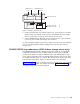

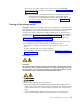
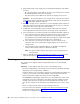

To create the redundant loop shown in Figure 54, you would perform the following
steps:
1. Make two fibre-channel connections from the First expansion unit to the Second
expansion unit (connections 1 and 2).
2. Make two fibre-channel connections from the Second expansion unit to the Last
expansion unit (connections 3 and 4). Currently, you can connect up to three
DS4000 EXP100s together in a redundant drive loop. Contact your IBM support
representative for information about the availability of future support for
connecting more than three DS4000 EXP100 units.
3. Make a fibre-channel connection from the storage server drive port to the OUT
port in the left ESM of the First expansion unit in the redundant drive loop
(connection 5).
4. Make a fibre-channel connection from the storage server drive port to the IN
port in the right ESM of the Last expansion unit in the redundant drive loop
(connection 6).
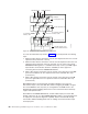
IBM SATA disk drives are dual-ported, providing individual access from two
fibre-channel loops to the same disk drive. When configuring the ESMs, configure
the second ESM the same way that you configured the first ESM. Refer to the
DS4100 Fibre Channel Cabling Instructions for more information about dual-loop
support and implementation.
Each ESM on the DS4000 EXP100 has an SFP module input port and an SFP
module output port. As you cable DS4000 EXP100s together, connecting input ports
to output ports can improve diagnostic capability. Refer to the DS4100 Storage
Server Fibre Channel Cabling Instructions for cabling connections between input
and output ports.
Second expansion unit
First expansion unit
DS4100 storage server
with two RAID controllers
Output
Input
Output
Left ESM board Right ESM board
Loop B Fibre Channel
interface cable
1
2
3
4
5
6
Loop A Fibre Channel
interface cable
Last expansion unit
f10ug048
Figure 54. DS4000 EXP100 redundant loop configuration
60 IBM TotalStorage DS4100 Storage Server: Installation, User’s, and Maintenance Guide