IBM TotalStorage DS4100 Storage Server Installation, User’s, and Maintenance Guide GC26-7712-00
IBM TotalStorage DS4100 Storage Server Installation, User’s, and Maintenance Guide GC26-7712-00
Note: Before using this information and the product it supports, be sure to read the general information in “Notices” on page 127. First Edition (November 2004) © Copyright International Business Machines Corporation 2004. All rights reserved. US Government Users Restricted Rights – Use, duplication or disclosure restricted by GSA ADP Schedule Contract with IBM Corp.
Safety The caution and danger statements that this document contains can be referenced in the multilingual IBM® Safety Information document that is provided with your IBM TotalStorage® DS4100 storage server. Each caution and danger statement is numbered for easy reference to the corresponding statements in the translated document. v Danger: These statements indicate situations that can be potentially lethal or extremely hazardous to you.
Statement 1: DANGER Electrical current from power, telephone, and communication cables is hazardous. To avoid a shock hazard: v Do not connect or disconnect any cables or perform installation, maintenance, or reconfiguration of this product during an electrical storm. v Connect all power cords to a properly wired and grounded electrical outlet. v Connect to properly wired outlets any equipment that will be attached to this product. v When possible, use one hand only to connect or disconnect signal cables.
Statement 3: CAUTION: When laser products (such as CD-ROMs, DVD drives, fiber optic devices, or transmitters) are installed, note the following: v Do not remove the covers. Removing the covers of the laser product could result in exposure to hazardous laser radiation. There are no serviceable parts inside the device. v Use of controls or adjustments or performance of procedures other than those specified herein might result in hazardous radiation exposure.
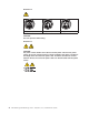
Statement 4: ≥ 18 kg (39.7 lb) ≥ 32 kg (70.5 lb) ≥ 55 kg (121.2 lb) CAUTION: Use safe practices when lifting. Statement 5: CAUTION: The power control button on the device and the power switch on the power supply do not turn off the electrical current supplied to the device. The device also might have more than one power cord. To remove all electrical current from the device, ensure that all power cords are disconnected from the power source.
Statement 8: CAUTION: Never remove the cover on a power supply or any part that has the following label attached. Hazardous voltage, current, and energy levels are present inside any component that has this label attached. There are no serviceable parts inside these components. If you suspect a problem with one of these parts, contact a service technician.
viii IBM TotalStorage DS4100 Storage Server: Installation, User’s, and Maintenance Guide
Contents Safety . . . . . . . . . . . . . . . . . . . . . . . . . . . . iii Figures . . . . . . . . . . . . . . . . . . . . . . . . . . . xiii Tables . . . . . . . . . . . . . . . . . . . . . . . . . . . . xv About this document . . . . . . . . . . . . . . . . . . . . . xvii FAStT product renaming . . . . . . . . . . . . . . . . . . . . . xvii Who should read this document . . . . . . . . . . . . . . . . . . xvii How this document is organized . . . . . . . . . . . . . . . . . .
Preparing the site . . . . . . . . . . . . Preparing the rack cabinet. . . . . . . . . Installing the DS4100 . . . . . . . . . . . Rack mounting template . . . . . . . . . Installing the support rails . . . . . . . . . Removing the CRUs . . . . . . . . . . . Removing a RAID controller . . . . . . . Removing a power supply . . . . . . . . Removing a fan . . . . . . . . . . . Removing a hard disk drive . . . . . . . Installing the DS4100 into a rack cabinet . . . Replacing the DS4100 CRUs . . . . . . .
Turning off the storage server . . . . . . . . . Restoring power after an unexpected shutdown . . . . Performing an emergency shutdown . . . . . . . Restoring power after an emergency shutdown . . . Restoring power after an over-temperature shutdown . Monitoring status through software . . . . . . . . Checking the LEDs . . . . . . . . . . . . . . Cache memory and RAID controller battery . . . . . Cache memory . . . . . . . . . . . . . . . RAID controller cache battery . . . . . . . . . . . . . . . . . . .
European Union EMC Directive conformance statement . . . . . . . . 129 Taiwan Class A warning statement . . . . . . . . . . . . . . . . 130 Japanese Voluntary Control Council for Interference (VCCI) statement 130 Glossary . . . . . . . . . . . . . . . . . . . . . . . . . . 131 Index . . . . . . . . . . . . . . . . . . . . . . . . . . . .
Figures 1. 2. 3. 4. 5. 6. 7. 8. 9. 10. 11. 12. 13. 14. 15. 16. 17. 18. 19. 20. 21. 22. 23. 24. 25. 26. 27. 28. 29. 30. 31. 32. 33. 34. 35. 36. 37. 38. 39. 40. 41. 42. 43. 44. 45. 46. 47. 48. 49. 50. Installation process flow by current publications . . . . . . . . . . . . . . . . . . . xix DS4100 hot-swap drive bays . . . . . . . . . . . . . . . . . . . . . . . . . . . 8 Front controls and indicators . . . . . . . . . . . . . . . . . . . . . . . . . . . 9 Back view of DS4100 base storage server . . . . . .
51. 52. 53. 54. 55. 56. 57. 58. 59. 60. 61. 62. 63. 64. 65. 66. 67. 68. 69. 70. 71. 72. 73. 74. 75. 76. 77. 78. 79. 80. 81. xiv Location of host cables (single-controller storage server) . . . . . . . Ethernet and serial port locations . . . . . . . . . . . . . . . . Adding an expansion unit . . . . . . . . . . . . . . . . . . . DS4000 EXP100 redundant loop configuration . . . . . . . . . . . Power cord locations . . . . . . . . . . . . . . . . . . . .
Tables 1. 2. 3. 4. 5. 6. 7. 8. 9. 10. 11. 12. 13. 14. 15. 16. 17. 18. 19. Mapping of FAStT names to DS4000 Series names . . . . . . . . . . . . . . . . . . xvii TotalStorage DS4500 storage server document titles by user tasks . . . . . . . . . . . . xx TotalStorage DS4400 storage server document titles by user tasks . . . . . . . . . . . . xxii TotalStorage DS4300 storage server document titles by user tasks . . . . . . . . . . . . xxiii TotalStorage DS4100 storage server document titles by user tasks . .
xvi IBM TotalStorage DS4100 Storage Server: Installation, User’s, and Maintenance Guide
About this document This document provides instructions for installing and customizing the configuration of your IBM TotalStorage DS4100 storage server. It also provides hardware maintenance procedures and troubleshooting information. FAStT product renaming IBM is in the process of renaming some FAStT family products. Table 1 identifies each new DS4000 product name with its corresponding FAStT product name. Note that this change of product name only indicates no change in functionality or warranty.
How this document is organized Chapter 1, “Introduction,” on page 1 describes the IBM TotalStorage DS4100 storage server. This chapter includes an inventory checklist and an overview of the storage server features, operating specifications, and components. Chapter 2, “Installing the storage server,” on page 17 contains instructions for installing the storage server in a standard rack cabinet and setting the interface options.
v Danger: These statements indicate situations that can be potentially lethal or extremely hazardous to you. A danger statement is placed just before the description of a potentially lethal or extremely hazardous procedure step or situation. Figures used in this document The figures used in this document are for illustrative purposes only. In some cases, the actual device might look different from the figure.
DS4000 Storage Server publications The following tables present an overview of the DS4500, DS4400, DS4300 Fibre Channel, and DS4100 SATA Storage Server product libraries, as well as other related documents. Each table lists documents that are included in the libraries and what common tasks they address. Click on active links in the tables to access those documents currently available on the Internet. You can access documentation for the other DS4000 products at the following Web site: www-1.ibm.
Table 2.
DS4400 storage server library Table 3 associates each document in the DS4400 (previously FAStT700) storage server library with its related common user tasks. Table 3.
DS4300 storage server library Table 4 associates each document in the DS4300 (previously FAStT600) storage server library with its related common user tasks. Table 4.
Table 5.
DS4000-related hardware publications Table 6 associates each of the following documents related to DS4000 (previously FAStT) operations with its related common user tasks. Table 6.
Table 6.
Getting information, help, and service If you need help, service, or technical assistance or just want more information about IBM products, you will find a wide variety of sources available from IBM to assist you. This section contains information about where to go for additional information about IBM and IBM products, what to do if you experience a problem with your IBM Eserver xSeries™ or IntelliStation system, and whom to call for service, if it is necessary.
v You can order publications through the IBM Publications Ordering System at the following web site: www.elink.ibmlink.ibm.com/public/applications/publications/cgibin/pbi.cgi/ v For the latest information about IBM xSeries products, services, and support, go to the following Web site: www.ibm.com/eserver/xseries/ v For the latest information about IBM pSeries products, services, and support, go to the following Web site: www.ibm.
Table 9 on page 14 lists the environmental specifications for the DS4100. How to send your comments Your feedback is important in helping us to provide the most accurate and high-quality information. If you have comments or suggestions for improving this publication, you can send us comments electronically by using these addresses: v Internet: starpubs@us.ibm.com v IBMLink from U.S.A.
xxx IBM TotalStorage DS4100 Storage Server: Installation, User’s, and Maintenance Guide
Chapter 1. Introduction This chapter describes the operating specifications, features, and components for the IBM TotalStorage DS4100 storage server (hereafter referred to as DS4100 or storage server). This chapter also includes a list of hardware that comes with the storage server. Overview IBM DS4000 solutions support the large and growing data storage requirements of business-critical applications.
connections for expanding the DS4100 storage capacity to SATA hard drives in external DS4000 EXP100 storage expansion units. Currently, the only DS4000 storage expansion unit model that can be attached to the DS4100 base storage server is the DS4000 EXP100. Do not connect other DS4000 storage expansion units (such as the DS4000 EXP700 or DS4000 EXP710) to the DS4100 base storage server.
v The DS4100 single-controller storage server does not support automatic firmware updates. All firmware upgrades and downgrades for the DS4100 single-controller storage server must be performed manually, as described in “Manually upgrading the firmware for the DS4100 single-controller storage server” on page 103. v All DS4100 single-controller storage server controller firmware updates must be performed off-line.
Go to the Personalized Support section of the web page and click My Support. On the next page, go to the We use IBM Registration section. To register to use this site, click Register. Perform the following steps to receive product updates: 1. Once you have registered, type your user ID and password to log into the site. The Welcome page opens. 2. In the Select a Product Family pull-down menu, scroll down to the listing of hardware topics and select Computer Storage. Click Go.
Clustering support Clustering is a means of sharing array groups among controllers to provide redundancy of controllers and servers. This redundancy is important if a hardware component fails. If a hardware component failure occurs in a cluster, another server takes ownership of the array group. Clustering requires software specific to your operating system. For more information about clustering, go to the following Web site: www.pc.ibm.com/us/compat/nos/matrix.
Your DS4100 storage server has 14 hard disk drive slots; any drive slots not containing hard disk drives will contain blank drive trays. Each of the 14 drive slots must always contain either a blank tray or a hard disk drive. – Box ID labels (used to label the storage server IDs on the front of the DS4100) – Wrap plug and coupler kit Attention: The DS4100 does not ship with region-specific power cords. You must obtain the IBM-approved power cords for your region.
the DS4000 storage expansion units attached to the DS4100 storage server should be plugged into the same two independent external power circuits as the DS4100. This ensures that the DS4100 storage server and all its attached storage expansion units will have power if only one power circuit is available.
Attention: The DS4100 single-controller storage server does not support hot-swap RAID controllers or power supplies. You will lose access to data if you attempt to remove or replace a functioning (non-failed) RAID controller or power supply in a DS4100 single-controller storage server without first powering down the storage server. Hot-swap drive bays The hot-swap drive bays that are accessible from the front of your storage server are shown in Figure 2. Hot-swap drive bays f10ug052 Figure 2.
Activity LED Fault LED General system error LED Latch Power-on LED f10ug053 Tray handle Figure 3. Front controls and indicators The DS4100 has blank trays in the unused drive bays. To begin installing new drives, you must first remove the blank trays and save them. Each of the 14 bays must always contain either a blank tray or a drive CRU. You can install up to 14 hot-swap drive CRUs in the storage server. v Activity LED: Each drive CRU has an associated Activity LED on the DS4100 chassis.
Hot-swap fan bays Raid controllers f10ug021 Hot-swap power supplies Figure 4. Back view of DS4100 base storage server Figure 5 shows the components at the back of the DS4100 single-controller storage server. The DS4100 single-controller storage server has a controller blank instead of a second RAID controller and a power supply blank instead of a second power supply. Hot-swap fan bays RAID controller f10ug021b Power supply Figure 5.
fan CRU continues to operate. You must install both fan CRUs to maintain proper cooling within the storage server, even if one fan CRU is not operational. Hot-swap power supplies The DS4100 base storage server comes with two hot-swap power supplies. You must install both power supplies to maintain proper cooling. The DS4100 single-controller storage server storage server comes with one power supply.
Ethernet Host port 2 Host port 1 Serial port AC power Server ID switch switch 1 Gbps/ 2 Gbps switch f10ug022scu AC power connector Expansion port (inactive in the DS4100 single-controller storage server) Figure 7. Interface ports and switches for DS4100 single-controller storage server RAID controller Each RAID controller contains several connectors and LEDs. Each controller has two host ports and one expansion port for connecting the storage server to hosts or expansion units.
Attention: When connecting the DS4100 to DS4000 EXP100 storage expansion units, DO NOT use the tens digit (x10) setting. Use only the ones digit (x1) setting to set unique server IDs or enclosure IDs. For more information, see “Server ID (enclosure ID) settings” on page 33. 1 Gbps/2 Gbps switch The default switch setting is 2 Gbps. This is the only speed setting that is allowed for the DS4100. Attention: Do not remove the metal plate that covers the storage server speed setting.
DS4100 specifications Table 9 lists the physical specifications for the DS4100. Table 9. IBM TotalStorage DS4100 specifications Size Heat dissipation v Width: 48.18 cm (18.97 in.) v Fully configured storage server (14 1.5 Gbps SATA hard disk drives) v Height: 13.23 cm (5.21 in.) v Depth: 59.74 cm (23.52 in.) – 1235 BTU per hour Weight Acoustical noise emission values v Drive-ready weight (without disk drive modules installed): – Model 100: 26.64 kg (58.
Table 10. IBM TotalStorage DS4100 AC power requirements Low Range High Range Nominal Voltage 90 to 136 VAC 180 to 264 VAC Frequency 50 to 60 Hz 50 to 60 Hz Idle Current 2.50 A a 1.33 Ab Maximum Operating Current 3.01 Aa 1.57 Ab a. Typical voltage: 115 V AC, 60 Hz at 77% power-supply efficiency and 0.96 power factor b. Typical voltage: 230 V AC, 60 Hz at 77% power-supply efficiency and 0.
back T42 racks front Air conditioner 1220 mm cold aisle width Perforated tiles or gratings Cold aisle front 2440 mm between center lines of hot and cold aisle T42 racks back Hot aisle back front Airflow Figure 8.
Chapter 2. Installing the storage server This chapter provides the information that you need to install the DS4100 into a rack cabinet. This chapter also contains information about cabling, setting interface options, and installing optional cables. Installation overview The following steps provide an overview of the installation process you will perform in this chapter. Each step is detailed in the sections following the overview. Statement 4: ≥ 18 kg (39.7 lb) ≥ 32 kg (70.5 lb) ≥ 55 kg (121.
10. Install the DS4000 Storage Manager 9.10 host software. Refer to the IBM TotalStorage DS4000 Storage Manager 9.10 Installation and Support Guide for the appropriate operating system for instructions on how to install the DS4000 Storage Manager 9.10 host software. 11. Turn on the DS4100. See “Turning the storage server on and off” on page 65. 12. Use the DS4000 Storage Manager 9.10 host software to verify the configuration.
CAUTION: Use safe practices when lifting. 3. Remove the DS4100 from its shipping container and check the contents (see “Inventory checklist” on page 5). If any items are missing, contact your IBM reseller before proceeding. 4. Assemble the tools and equipment that you will need for installation.
v Always connect the storage server to a properly grounded outlet. v Always connect the rack power distribution units (PDUs) to at least two different power circuits or sources. Complete the following steps to prepare the rack cabinet before you install the DS4100: 1. Move, unpack, and level the rack cabinet at the installation site (if needed). 2. Remove the external rack panels. 3. If necessary, stop all I/O activity to the devices in the rack cabinet. 4.
3U 3U DS4100 FRONT Rack Mounting Template 2U 2U Bezel (Front Left) Bezel (Front Right) 1U 1U Rail assembly (Front Left) 0U f10ug058 0U Rail assembly (Front Right) Figure 9. Front rack mounting template Chapter 2.
3U 3U DS4100 REAR Rack Mounting Template 2U 2U 1U 1U Rail assembly (Rear Right) Rail assembly (Rear Left) ® 0U f10ug059 Printed in the U.S.A. 0U Figure 10. Rear rack mounting template Installing the support rails Before installing the DS4100 in a rack cabinet, you must install the rails and rack-mounting hardware that come with your storage server. The DS4100 requires an Electronic Industries Association (EIA) 310-D Type A 19-inch rack cabinet.
Attention: Both support rails are shipped with three screws and spacers, called alignment pins, already installed at the front of each rail. They have been inserted in the front of each support rail as guides to indicate where not to use M6 screws when you attach the front of the support rail to the rack cabinet. See Figure 11. Alignment pins with spacers 1 2 Alignment pin without spacer 3 f10ug057 Figure 11.
5. Starting with the left rail, remove and save the 6/32 in. screw ( 5 ). Loosen the four rail adjustment screws ( 2 ). 6. 7. 8. 9. Note: The support rails are not marked as Left or Right. However, each rail can be correctly mounted on only one side of the rack cabinet. The rails should be mounted with the alignment pins at the front of the rack cabinet. Figure 12 shows the installation of the left support rail.
Removing the CRUs Attention: This section describes how to remove the CRUs in order to minimize the weight of the DS4100 before you install it in the rack cabinet. However, if you have three or more people available to lift and install the DS4100 in a rack cabinet, you might not find it necessary to remove the CRUs before you install the DS4100. If this is the case, you can skip the CRU removal instructions provided in this section.
1. Push down on the latch (centered above the RAID controller). Pull both levers at the same time out of the locked position. f10ug033 Figure 13. Removing a RAID controller 2. Grasp the pull-rings; then pull on the levers and remove the RAID controller. 3. Place the RAID controller on a level surface. 4. For the DS4100 base storage server, repeat step 1 through step 3 for the second RAID controller. Note: In the DS4100 single-controller storage server, you do not need to remove the controller blank.
Lever Pull ring f10ug054 Figure 14. Removing a power supply 3. Place the power supply on a level surface. 4. For the DS4100 base storage server, repeat step 1 through step 3 for the second power supply. Note: In the DS4100 single-controller storage server, you do not need to remove the power supply blank. Removing a fan Complete the following steps to remove a fan: 1. Unlock the latch by moving the latch in the same direction as the latch direction arrow shown on the back of the fan. 2.
Removing a hard disk drive Complete the following steps to remove a hot-swap hard disk drive: Note: The hard disk drive comes installed in a drive tray. Do not attempt to detach the hard disk drive from the drive tray. 1. Use Table 19 on page 119 to record the location and identify your DS4000 SATA hard disk drives. You must record this information to be able to replace the hard disk drives in their original order before they were removed. 2.
Front of Rack f10ug051 Figure 17. Installing the DS4100 2. The bezel is secured to the front of the DS4100 either by plastic wingnuts or by adhesive tape. Remove and discard the wingnuts or the adhesive tape. The bezel should remain attached to the DS4100 chassis. Attention: The bottom cross member of the bezel has a tab that must fit beneath the DS4100 chassis and snap into place. The top cross member of the bezel has a recess that must be mated with a metal tab on the bottom of the DS4100 chassis. 3.
Replacing a RAID controller Complete the following steps to replace the RAID controller that you removed before the installation: f10ug033 Figure 18. Replacing a RAID controller 1. Slide the RAID controller all the way into the empty slot. 2. Close both levers until the latch locks into place. Attention: Make sure that the levers lock into place in the storage server chassis. 3. For the DS4100 base storage server, repeat step 1 and step 2 to replace the second RAID controller.
Lever Pull ring f10ug054 Figure 19. Replacing a power supply 2. Close the lever until the pull-ring latch locks in place. Make sure that the lever locks into place in the storage server chassis. Then gently push the front of the power supply to ensure that it is fully seated. 3. For the DS4100 base storage server, repeat step 1 and step 2 to replace the second power supply. Replacing a fan Complete the following steps to replace the fan units that you removed before the installation: 1.
3. If the latch does not automatically lock when you have successfully inserted the fan unit into the bay, pull back slightly on the fan and then push it in again until the latch snaps into place. 4. Repeat step 1 through step 3 to replace the second fan. Replacing a hard disk drive Complete the following steps to replace the hot-swap hard disk drives that you removed before the installation. Note: Use Table 19 on page 119 to verify the proper replacement locations of your DS4000 1.
1 Gb/s X10 2 Gb/s X1 Conflict Tray Number 1 Gb/s 2 Gb/s 2 Gb/s Enclosure Speed LED (Green) Server ID switch ID Conflict LED (Amber) X10 X1 f10ug046 Tray Number Conflict Figure 22. Enclosure ID switches Fibre channel loop and ID settings When you install a hard disk drive in the expansion unit, the drive tray plugs into a printed circuit board called the midplane.
valid for the drive loop. The amber Conflict LED (located on the right-side of the switch) will be lit if another unit in the drive loop has the same ID setting as the server ID. Attention: When connecting the DS4100 to DS4000 EXP100 storage expansion units, DO NOT use the tens digit (x10) setting. Use only the ones digit (x1) setting to set unique server IDs or enclosure IDs. Give each drive expansion enclosure in a redundant drive loop a unique ones digit (x1) ID.
Controller Controller Host-agent software Ethernet Client software Management station (one or more) Fibre Channel I/O path Note: The client software is installed on one or more management systems, or on the host computer. Controller f10ug004 Controller Figure 23. Host-agent (in-band) managed storage subsystems Direct (out-of-band) management method This method uses Ethernet connections from a management station to each controller. You must install at least one management station.
Controller Controller Host computer Controller Controller Fibre Channel I/O path Note: The client software is installed on one or more management systems, or on the host computer. Storage subsystems f10ug008 Ethernet Management station Figure 24. Direct (out-of-band) managed storage subsystems Fibre channel connections The storage server fibre channel connection consists of up to four host fibre-channel loops and a redundant drive fibre-channel loop.
connect more than two hosts to the fibre channel storage server through switches. The illustrations in the following sections show common host system configurations. Note: The default configuration is one partition. Four-partition, eight-partition, and sixteen-partition configuration upgrades are available as upgrade options.
Host system with two host adapters Host system with two host adapters Host system with two host adapters Note: Node level redundancy with cluster software. Switch Switch DS4100 DS4100 Host system with two host adapters Host system with two host adapters DS4100 f10ug028 Figure 25.
Host system with two host adapters Host system with two host adapters Switch Switch Interswitch link f10ug043 DS4100 Figure 26. Example of a single SAN fabric configuration (base storage server) In Figure 27, the fibre channel switches are not connected together. Each switch forms its own SAN fabric. Host system with two host adapters Host system with two host adapters Switch Switch DS4100 f10ug042 DS4000 EXP100 (Expansion unit) DS4100 Figure 27.
Host system with two host adapters Host system with two host adapters Host system with two host adapters Host system with two host adapters Switch Switch Switch Switch f10ug044 DS4100 Figure 28. Example of a two-cluster configuration (base storage server) DS4100 single-controller storage server configurations: This section provides the following examples of DS4100 single-controller storage server host fibre channel configurations.
DS4100 Single Controller f11ug002 Host Server Figure 30. Example of a single server configuration with two adapters (single-controller storage server) Host Server DS4100 Single Controller f11ug003 Host Server Figure 31. Example of a dual server configuration with one adapter on each server (single-controller storage server) Chapter 2.
Host Server Host Server DS4100 Single Controller f11ug004 FC Switch Figure 32. Example of a dual-server, single-SAN fabric configuration with one adapter on each server (single-controller storage server) Host Server Host Server D4100 Single Controller DS4100 Single Controller f11ug005 FC Switch FC Switch Figure 33.
2. Use the correct host adapter driver. For the latest supported host adapters and drivers, go to the following Web site: www.ibm.com/servers/storage/disk/ Attach fiber-optic interface cables to each host adapter. You will connect the other end of the cables to the controller later in the installation process. For more information about handling fiber-optic cables, see “Handling fiber-optic cables” on page 45.
44 IBM TotalStorage DS4100 Storage Server: Installation, User’s, and Maintenance Guide
Chapter 3. Cabling the storage server This chapter provides fibre channel and power cabling information for the storage server. After you attach the storage server power cables, use the instructions that are provided in “Turning the storage server on and off” on page 65 for the initial startup of the storage server. Working with SFPs and fiber-optic cables Each RAID controller has two host ports and one expansion port.
v Do not overtighten the cable straps or bend the cables to a radius of less than 38 mm (1.5 in.). v Do not put excess weight on the cable at the connection point. Be sure that the cable is well supported. Installing SFP modules The DS4100 host ports require SFP modules. SFP modules are used to convert electrical signals to optical signals that are required for fibre channel transmission to and from RAID controllers.
DANGER Some laser products contain an embedded Class 3A or Class 3B laser diode. Note the following. Laser radiation when open. Do not stare into the beam, do not view directly with optical instruments, and avoid direct exposure to the beam. Attention: When you handle static-sensitive devices, take precautions to avoid damage from static electricity. For details about handling static-sensitive devices, see “Handling static-sensitive devices” on page 18. 1.
Removing SFP modules To remove the SFP module from the host port, perform the following steps. Attention: To avoid damage to the cable or to the SFP module, make sure you unplug the LC-LC fibre channel cable before you remove the SFP module. 1. Remove the LC-LC fibre channel cable from the SFP module. For more information, see “Handling fiber-optic cables” on page 45. 2.
1. Remove the protective cap from the fiber-optic cable. See Figure 38. Fiber-optic cable Protective cap F10ug011 Figure 38. Removing caps from fiber-optic cables 2. Connect the fiber-optic cable to the installed SFP, as shown in Figure 39. RAID controller SFP module f10ug041 Fiber-optic cable Figure 39. Connecting cables to the installed SFP 3. Check the LEDs on the RAID controller. When the RAID controller is operating properly, the amber Fault LED is off.
For more information about cabling these devices, see the documentation that comes with the LC-LC fibre-channel cable. fg0ug019 Figure 40. LC-LC fibre-channel cable Note: If you are connecting the DS4100 to a 1 Gbps device (such as a 1 Gbps fibre channel switch), you must also use an LC-SC fibre-channel cable adapter. For more information about using an LC-SC fibre-channel cable adapter, see “Using LC-SC fibre-channel cable adapters” on page 52.
2. If necessary, remove the protective cap from the SFP module, as shown in Figure 34 on page 47. Save the protective cap for future use. 3. Remove the two protective caps from one end of the LC-LC cable, as shown in Figure 41. Save the protective caps for future use. Fiber-optic cable Protective cap F10ug011 Figure 41. Removing fiber-optic cable protective caps 4. Carefully insert this end of the LC-LC cable into an SFP module that is installed in the DS4100.
1. On the end of the LC-LC cable that connects into the SFP module or host bus adapter, press down and hold the lever to release the latches, as shown in Figure 43. Lever f10ug018 Latches Figure 43. LC-LC fibre-channel cable lever and latches 2. Carefully pull on the connector to remove the cable from the SFP module, as shown in Figure 44. f10ug017 Figure 44. Removing the LC-LC fibre-channel cable 3. Replace the protective caps on the cable ends. 4. Replace the protective cap on the SFP module.
LC connector f10ug012 SC connector Figure 45. LC-SC fibre-channel cable adapter The following sections provide the procedures for properly connecting and removing an LC-SC fibre-channel cable. Connecting an LC-SC cable adapter to a device Complete the following steps to connect an LC-SC fibre-channel cable adapter to a device: Statement 3: CAUTION: When laser products (such as CD-ROMs, DVD drives, fiber optic devices, or transmitters) are installed, note the following: v Do not remove the covers.
3. Remove the two protective caps from the LC connector end of the LC-SC cable adapter as shown in Figure 46. Save the protective caps for future use. f10ug013 Figure 46. Removing the LC-SC cable adapter protective caps 4. Carefully insert the other end of the LC-LC cable into the LC connector end of the LC-SC cable adapter as shown in Figure 47. Push in the connector until it clicks into place. f10ug020 Figure 47. Connecting an LC-LC cable into the LC-SC cable adapter 5.
1. On the end of the cable that connects into the LC connector end of the LC-SC cable adapter, press down and hold the lever to release the latches. Figure 48 shows the location of the lever and latches. Lever f10ug018 Latches Figure 48. LC-LC fibre-channel cable lever and latches 2. Carefully pull on the connector to remove it. Make sure you grasp the connector and not the cable when removing the LC-LC cable from the LC-SC cable adapter as shown in Figure 49. f10ug015 Figure 49.
Controller A Controller B f10ug029 Host A: Host Adapter 1 (or from managed hub or switch) Host A: Host Adapter 2 (or from managed hub or switch) Figure 50. Location of host cables (base storage server) For examples of redundant, partially-redundant, and non-redundant host and drive loop configurations, see “Fibre channel loop configurations” on page 36.
Important: 1. The serial interface ports are intended to be used by service technicians to perform diagnostic operations on the storage server. Incorrect use of the serial port can result in loss of data access and, in some cases, in loss of data. 2. Do not connect the DS4100 in a public LAN or public subnet. Use a local private network for the DS4100 storage server and the management station Ethernet ports. 3. To ensure proper EMI shielding, always use quality shielded serial cables.
Attention: In the initial installation of the DS4100, you can add only new expansion units to the DS4100 storage server. This means that there must be no existing configuration information on the expansion unit that you want to install.
Left ESM board In port Right ESM board Out port New expansion unit f10ug031 Storage server with two RAID controllers Figure 53. Adding an expansion unit 3. Remove the blank filler trays and insert drive trays. Connect power to the drive expansion unit first and then connect power to the DS4100. After the storage server is powered on, the storage server locates the new drives. 4.
Left ESM board Input Right ESM board Output Output Last expansion unit 3 4 Second expansion unit 6 Loop A Fibre Channel interface cable 1 2 Loop B Fibre Channel interface cable First expansion unit 5 f10ug048 DS4100 storage server with two RAID controllers Figure 54. DS4000 EXP100 redundant loop configuration To create the redundant loop shown in Figure 54, you would perform the following steps: 1.
Power cabling The DS4100 base storage server uses two standard power cords, and the single-controller storage server uses only one. You can connect the power cords to a primary power unit inside the rack cabinet, such as a properly grounded ac distribution unit, or to an external source, such as a properly grounded electrical outlet. The DS4100 storage server does not ship with power cords. Refer to Appendix C, “Power cords,” on page 125 for the list of IBM-approved power cords for your region.
one-half of the current load. If there is only one power supply unit, it will handle all of the current load. To ensure maximum protection against power loss due to power supply unit failure or a power circuit tripping, both power supply units must be connected and powered on. See Table 10 on page 15 for the DS4100 AC power requirements. See Figure 56 for an example of redundant power cabling.
system documentation to make the new logical drives accessible to the operating system. Do not proceed with the configuration set-up you have completed the DS4000 Storage Manager installation. Assemble any additional items in preparation for software installation. These items might include: v HBA drivers v Controller firmware version 05.42.xx.xx v IP addresses for RAID controllers (for in-band management only) v Additional documentation for switches and HBAs, if needed v DS4000 Storage Manager Version 9.
64 IBM TotalStorage DS4100 Storage Server: Installation, User’s, and Maintenance Guide
Chapter 4. Operating the storage server To ensure optimal operation of your system, always follow these best practices guidelines: v Back up the data on your storage drives periodically. v DS4100 base storage server only: To maintain power redundancy, plug the storage server’s right and the left power supplies into two independent external power circuits through ac distribution units inside a rack cabinet or directly into external receptacles.
Turning on the storage server Important: DS4100 base storage server only: You must turn on the storage expansion units and verify that the storage expansion unit fibre channel connections are optimal by checking the indicator lights before you turn on the DS4100. The controllers might not recognize the correct configuration if the hard disk drives are powered up after the DS4100. For instructions on how to power up the storage expansion units, refer to the storage expansion unit documentation.
green on the front of the storage server. If they are not, use the DS4000 Storage Manager client to diagnose the problem (see “Monitoring status through software” on page 70). Note: The green drive active LED and amber drive fault LED below the drive CRUs might flash intermittently as the drives spin-up. Wait until the storage server is finished powering up before checking the LEDs on the front of the storage server. For more information, see “Checking the LEDs” on page 71.
3. Stop all I/O activity to the storage server and attached expansion units. Make sure that: v All of the green Drive active LEDs on the front of the storage server (and on all attached expansion units) are not flashing. v The green Cache active LEDs on the back of the storage server are off. Attention: To turn off all power to the storage server, you must turn off both power-supply switches and disconnect both power cords. Use the procedure in step 6 for the proper shutdown sequence. 4.
Attention: To avoid damage to the hardware, take special care when you restart the system after an unexpected shutdown. If the storage server shuts down unexpectedly, go to “Restoring power after an over-temperature shutdown.” Otherwise, go to “Restoring power after an emergency shutdown.
4. Complete step 2 on page 66 to determine the proper power-on sequence for your system. 5. When the internal temperature of the storage server is below 35° C (95° F), complete steps 3 and 4 on page 66 to turn on power to the devices in your system and to check the status of the storage server.
v Locate the failed component v Determine the recovery procedures to repair the failure Although the storage server has fault LEDs, these lights do not necessarily indicate which component has failed or needs to be replaced, or which type of recovery procedure you must perform. In some cases (such as loss of redundancy in various components), the fault LED does not turn on. Only the DS4000 Storage Manager client can detect the failure.
Activity LED Fault LED General system error LED Latch Power-on LED f10ug053 Tray handle Figure 57. Storage server LEDs (front) Table 12. Storage server LEDs (front) LED Color Operating states1 Drive active Green v On - Normal operation. v Flashing - The drive is reading or writing data. v Flashing every 5 seconds - The drive has not spun up or the drive is bad. v Off - One of the following situations has occurred: – The storage server has no power.
Expansion link indicator 2Gbps Host 1 Expansion Host 2 10101 10BT 2Gb/s 100BT + 2Gb/s 100BT 10BT Battery charging Cache Controller active fault f10ug025 Host 2 Host 1 indicator indicator Expansion by-pass Figure 58. RAID controller LEDs Table 13. RAID controller LEDs Icon LED Color Operating states1 Fault Amber v Off - Normal operation. v On - One of the following situations has occurred: – The RAID controller has failed.
Table 13. RAID controller LEDs (continued) Icon LED Color Operating states1 Expansion port bypass Amber v Off - Normal operation. v On - One of the following situations has occurred: – An SFP module is inserted in the drive loop port and the fibre-channel cable is not attached to it. – The fibre-channel cable is not attached to an expansion unit. – The attached expansion unit is not turned on. – An SFP has failed, a fibre-channel cable has failed, or an SFP has failed on the attached expansion unit.
Table 14. Fan LED (continued) LED 1 Color Operating states1 Always use the DS4000 Storage Manager client to identify the failure. Table 15. Power supply LEDs LED Color Operating states1 Fault Amber v Off - Normal operation. v On - One of the following situations has occurred: – The power supply has failed. – An over-temperature condition has occurred. Power Green v On - Normal operation. v Off - One of the following situations has occurred: – The power supply is disconnected.
Note: Always use the DS4000 Storage Manager client to check your cache memory settings before assuming a hardware failure. Figure 60 shows the location of the Cache active LED on the front of the RAID controller. f10ug036 Cache active LED Figure 60. Cache active LED RAID controller cache battery Each RAID controller contains a sealed, rechargeable 4-volt lead-acid battery. This battery provides cache backup for up to three days in the event of a power loss.
f10ug037 Battery LED Figure 61. Battery LED Chapter 4.
78 IBM TotalStorage DS4100 Storage Server: Installation, User’s, and Maintenance Guide
Chapter 5. Installing and replacing components This chapter provides instructions to help you install or remove customer replaceable units (CRUs), such as hot-swap drives, fans, RAID controllers, and power supplies. This chapter also provides instructions to help you add new DS4000 EXP100 expansion units to existing DS4100 configuration. For more CRU and Option part number information, see the following Web site: www-1.ibm.
Attention: After you remove a drive CRU, wait at least 70 seconds before replacing or reseating the drive CRU to allow the drive to properly spin down. Failure to do so may cause undesired events. Before you install or remove drive CRUs, review the following information: v Blank trays: A storage server without a full set of drives (14) contains blank trays in the unused drive bays. Before installing new drives, you must remove these empty trays. Save the empty trays for future use.
1. Read the documentation that comes with the hard disk drive. 2. Check for Fault LEDs shown in Figure 62. If any amber LEDs are lit, see Chapter 6, “Hardware maintenance,” on page 111. Activity LED Fault LED General system error LED Latch Power-on LED f10ug053 Tray handle Figure 62. Hot-swap hard disk drive LEDs 3. Determine the bay into which you want to install the drive. 4. Remove the blank tray: Note: To locate blank drives, look at the Activity LEDs on the front of the storage system.
b. Pull the handle on the tray out so that it is in the open position, as shown in Figure 63. Tray handle Tray latch f10ug049 Figure 63. Drive CRU handle c. Slide the drive CRU into the empty bay until the hinge of the tray handle latches beneath the storage server bezel. d. Push the tray handle down until it latches into place.
a. Release the latch on the drive CRU by pinching together the blue line on the tray latch and the finger hole on the tray handle, as shown by the arrow in Figure 63 on page 82. b. Pull the tray handle out into the open position. c. Lift the drive CRU partially out of the bay. d. To avoid possible damage to the drive, wait at least 70 seconds before fully removing the drive CRU from the storage server to allow the drive to stop (spin down). e.
to use the storage server (or any expansion units attached to the storage server) until you finish the procedure. You must use this method on RAID 0 logical drives. v Replacing the drives one at a time In this method, you manually fail each drive, replace it, and wait for the system to restore data to the new drive before installing the next drive. After you install the new drives, you can configure them to make the additional drive space available.
2. Use the DS4000 Storage Manager client to check the status of the storage server. Correct any problems that are reported. 3. Perform a complete backup of the drives that you are replacing. You need the backup to restore data on the drives later in this procedure. Attention: When you handle static-sensitive devices, take precautions to avoid damage from static electricity. For details about handling static-sensitive devices, see “Handling static-sensitive devices” on page 79. 4. Unpack the new drives.
b. You must turn on the expansion units before the storage server. The controllers might not recognize the correct configuration if the drives are powered up after the storage server. For instructions on powering up the expansion units, see the expansion-unit documentation. c. Turn on the power to the storage server; then restart or turn on the power to the host. 9. Turn on the power to each device, based on the power-on sequence in step 8 on page 85.
Attention: When you handle static-sensitive devices, take precautions to avoid damage from static electricity. For details about handling static-sensitive devices, see “Handling static-sensitive devices” on page 79. 4. Unpack the new drives. Set the drives on a dry, level surface away from magnetic fields. Save the packing material and documentation in case you need to return the drives. 5.
8. Use the DS4000 Storage Manager client to monitor the status of the new drive and the progress of the data reconstruction. Wait for data reconstruction to finish (the Drive activity LED stops flashing). Note: The Drive activity LED will continue to flash after reconstruction is finished if there is I/O activity to that drive. In that case, use the host software to determine if the data reconstruction is finished. 9.
Both fan units must always be in place, even if one is not functioning properly, to maintain proper cooling. Use the following procedure to replace a hot-swap fan: 1. Check the LEDs on the back of the storage server. 2. If the amber Fault LED is on, remove the fan CRU that has failed. a. Slide the latch to unlock the fan CRU. b. Use the handle (black knob) to pull the fan from the storage server. See Figure 65. f10ug038 Figure 65. Removing a fan 3. Install the new fan unit. a.
to “Turning off the storage server” on page 67 and follow the procedure described there before replacing the power supply on a DS4100 single-controller storage server. Each power supply CRU has a built-in sensor that detects the following conditions: v Over-voltage v Over-current v Overheated power supply If any of these conditions occurs, one or both power supplies will shut down.
AC power connectors This connection is for the ac power cord. Strain-relief clamp Use this clamp to provide strain relief on the power cord. Secure the clamp tightly with the power-supply clamp-nut. Removing a power supply Statement 8: CAUTION: Never remove the cover on a power supply or any part that has the following label attached. Hazardous voltage, current, and energy levels are present inside any component that has this label attached. There are no serviceable parts inside these components.
Lever Strain-relief clamp f10ug027 AC power connector AC power switch Figure 67. Lever for power supply removal 3. Unplug the power cord from the electrical outlet. 4. Disconnect the power cord from the ac power connector on the power supply. 5. Remove the power-supply nut and power-supply cable strain-relief clamp from the rear of the power supply. 6. Remove the power supply from the storage server, as follows: a. Grasp the pull-ring on the power-supply lever and squeeze the latch to release it. b.
Statement 8: CAUTION: Never remove the cover on a power supply or any part that has the following label attached. Hazardous voltage, current, and energy levels are present inside any component that has this label attached. There are no serviceable parts inside these components. If you suspect a problem with one of these parts, contact a service technician. 1. Ensure that the ac power switch is off on the power supply that you are installing. 2.
power to the storage server. Go to “Turning on the storage server” on page 66 and follow the procedure described there before proceeding with the following step. 9. Make sure that the green Power LED on the new power-supply CRU is on and the amber Fault LED is off. v If the Power LED is off, the power-supply CRU might not be installed correctly. Remove it and then reinstall it. v If the Fault LED is on or the Power LED stays off, test the power source to verify that the outlet is working properly.
inserted into DS4100 controller slots. Unpredictable results can occur when nonmatching controller CRUs are present in the same DS4100 chassis. v After the new controller in a DS4100 single-controller storage server completes the boot process, its WWNN will change. If you have any applications that rely on the previous WWNNs, such as fibre channel switch zoning definitions, you must update the applications with the new WWNNs.
Replacing a RAID controller When instructed to do so by the DS4000 Storage Manager client, replace a RAID controller that has failed. The procedure for replacing a failed controller is different for DS4100 single-controller and base (dual-controller) storage servers. If a controller in a DS4100 base storage server fails, you can replace the failed controller without interrupting data processing. The system will automatically update the firmware for the new controller to match the configuration database.
Note: Avoid operating the DS4100 with controllers of different cache sizes. Operating the storage server with controllers of different cache size will disable caching and might adversely affect performance. Always verify that you replace a failed controller with a controller that has the same FRU part number. To replace a RAID controller, perform the following steps: 1. DS4100 single-controller storage server only: The DS4100 single-controller storage server has only one RAID controller.
b. Unlock the SFP module latch: v For SFP modules that contain plastic tabs, unlock the SFP module latch by pulling the plastic tab outward 10°, as shown in Figure 72. Plastic tab Protective cap 10 o SFP module F10ug009 Figure 72. Unlocking the SFP module latch - plastic variety v For SFP modules that contain wire tabs, unlock the SFP module latch by pulling the wire latch outward 90°, as shown in Figure 73. Wire tab Protective cap o 90 F10ug010 SFP module Figure 73.
f10ug033 Figure 74. Pull-rings for removing a controller b. Grasp the pull-rings; then pull on the levers and remove the RAID controller. 7. To access the cache battery, place the RAID controller CRU bottom up on a flat surface. Using a #2 Phillips head screwdriver, remove the six screws (three on each side of the RAID controller) that hold the RAID controller bottom panel to the sides of the RAID controller, as shown in Figure 75.
Battery Harness Two-Pin Battery f10ug045 Figure 76. Removing the controller battery 10. Remove the screw that holds the battery access panel. Carefully slide the access panel toward the front to unlatch it from the three pins mounted on the RAID controller bottom panel. 11. Remove the battery unit and place it on a dry, level surface. If this is a battery replacement, then replace the old battery with the new one and go to step 19 on page 101. 12. Unpack the new RAID controller.
v Replacement Date – Copy the expiration date from the battery label on the old controller. Note: The preferred method of checking for the battery operating age is through the storage server management software. 19. Position the battery inside the replacement RAID controller. 20. Reassemble the battery access panel to the RAID controller bottom panel by aligning it with the three pins on the RAID controller bottom panel.
The startup process should complete within five minutes. After the startup process completes, the new RAID controller can accept I/Os from the host server and is ready to be managed by the DS4000 Storage Manager client. Note: If the new RAID controller is not recognized by the DS4000 Storage Manager client, use the Enterprise Management Window to rediscover the DS4100, as described in the following steps. a. Remove the entry for the DS4100 from the management domain of the DS4000 Storage Manager client. b.
Go to “Manually upgrading the firmware for the DS4100 single-controller storage server.” 28. For the DS4100 base storage server: See the DS4000 Storage Manager client online help for instructions on bringing the controller online. The RAID controller replacement procedure for the DS4100 base storage server is completed. 29.
All factory-delivered DS4100 RAID controllers are shipped with a recent version of controller firmware loaded on the RAID controller, but that firmware version might not match precisely the firmware version of the failed RAID controller you have replaced.
10. Use the SMW to download firmware to the new controller to match the version number shown in your storage subsystem profile. (Refer to your printout.) After 15-20 minutes, the SMW reports a download failure. Click OK to ignore the error warning and instructions and proceed with the following step. 11. Use the EMW to remove the RAID controller from the management domain, and again add the new controller using the IP address assigned to the new controller by the IP server. 12.
might involve clearing cache memory on the RAID controller that contains the battery that needs to be replaced. This is done by either placing the controller offline before removing it from the DS4100 server or turning off caching in the DS4100 server, using the DS4000 Storage Manager client. Follow the steps given in the software procedure before you continue with this procedure. Attention: When you handle static-sensitive devices, take precautions to avoid damage from static electricity.
v Installed date – Write today’s date v Replacement Date – Write the date three years from today’s date Note: The preferred method of checking for the battery operating age is through the storage server management software. CONTAINS SEALED LEAD BATTERY. BATTERY MUST BE RECYCLED. Pb CAUTION: This product contains a sealed lead acid battery. The battery must be recycled or disposed of properly.
sealed lead acid batteries outside the United States, go to http:// www.ibm.com/ibm/environment/products/batteryrecycle.shtml or contact your local waste disposal facility. 20. Install the RAID controller, as shown in Figure 77. f10ug033 Figure 77. Installing a new RAID controller a. Slide the RAID controller all the way into the empty slot. b. Close both levers until the latch locks into place. 21. Install the SFPs and then connect the fibre-channel cables to their original locations. 22.
Installing SFPs and fiber-optic cables Each RAID controller unit has two host ports and one expansion unit port. SFPs are inserted into the ports, and then fibre-channel cables are connected to the SFPs. For information on installing SFPs and fiber-optic cables, see “Working with SFPs and fiber-optic cables” on page 45. Adding a DS4000 EXP100 to an existing DS4100 configuration (base storage server only) You can add up to seven DS4000 EXP100 storage expansion units to a DS4100 storage server.
Drive loop A Fibre Channel interface cables Drive loop B Fibre Channel interface cables Input Output Input Output 2 New DS4000 EXP100 Drive enclosures group 1 3 1 Drive loop A Second DS4000 EXP100 First DS4000 EXP100 Drive loop B Drive loop C Drive Expansion Port A Drive Expansion Port B f10ug047 Storage server Figure 78. Cabling the DS4100 to a redundant loop In Figure 78, the existing DS4100 configuration already includes two DS4000 EXP100s.
Chapter 6. Hardware maintenance This chapter contains information to help you solve some of the simpler problems that you might have with your storage server. It contains the problem indicators and error messages along with suggested actions to take to resolve the problem. For instructions on how to obtain service and technical assistance for your storage server and other IBM products, see “Getting information, help, and service” on page xxvii.
Table 17. Symptom-to-FRU index Problem indicator Component Possible cause Possible solutions Amber LED on Drive CRU Drive failure Replace the drive that has failed. Fan CRU Fan failure Replace the fan that has failed. RAID controller Fault LED RAID controller failure If the RAID controller Fault LED is on, replace the RAID controller. If the RAID controller has been placed offline by the user, use storage management software to place it online.
Table 17. Symptom-to-FRU index (continued) Problem indicator Component All green LEDs off All CRUs Possible cause Possible solutions Subsystem power is off Check that all storage-server power cords are plugged in and the power switches are on. If applicable, check that the main circuit breakers for the rack cabinet are turned on. AC power failure Check the main circuit breaker and ac outlet. Power supply failure Replace the power supply.
Table 17. Symptom-to-FRU index (continued) Problem indicator One or more green LEDs off (continued) Component Possible cause Possible solutions Expansion loop Drives are improperly installed or not installed Ensure that the drives are properly installed. RAID controller has no power or has failed Ensure that the unit is powered on. Replace the RAID controller. Impending drive failure A bad drive or drives can issue LIPs that cause the drive expansion loop to go down momentarily.
Table 17. Symptom-to-FRU index (continued) Problem indicator Component The DS4000 Controller Storage Manager client Enterprise Management window sees each storage server controller as an independent storage subsystem or a partially managed device. Possible cause Possible solutions No drives are present in the storage server. Ensure that at least one drive is present in the storage server so that it can be configured properly. One controller was replaced incorrectly.
2 1 3 8 4 7 5 6 Figure 79. DS4100 parts list Table 18.
Table 18. Parts listing (TotalStorage DS4100 storage server) (continued) Index DS4100 storage server FRU P/N Cable, FRU-1M 19K1265 Cable, FRU-5M 19K1266 Cable, FRU-25M 19K1267 Short wave SFP 19K1280 Long wave SFP 19K1281 Power cord, 2.8M 6952300 Power cord, jumper 36L8886 Battery 24P8062 Wrap plug (loopback adapter) 17P6918 LC-SC fibre channel cable adapter 19K1268 Chapter 6.
118 IBM TotalStorage DS4100 Storage Server: Installation, User’s, and Maintenance Guide
Appendix A. Records Whenever you add options to your DS4100, be sure to update the information in this appendix. Accurate, up-to-date records make it easier to add other options and provide needed data whenever you contact your IBM technical support representative. Identification numbers Record and retain the following information.
120 IBM TotalStorage DS4100 Storage Server: Installation, User’s, and Maintenance Guide
Appendix B. Rack mounting template This appendix provides duplicate copies of the rack mounting templates. If you want to tear out the templates from this document for easier use, use these copies rather than those provided in “Rack mounting template” on page 20. Use the following templates (Figure 80 on page 122 and Figure 81 on page 123) to identify the proper locations for inserting M6 screws when mounting the support rails and DS4100 in a rack cabinet.
3U 3U DS4100 FRONT Rack Mounting Template 2U 2U Bezel (Front Left) Bezel (Front Right) 1U 1U Rail assembly (Front Left) Rail assembly (Front Right) Figure 80.
3U 3U DS4100 REAR Rack Mounting Template 2U 2U 1U 1U Rail assembly (Rear Left) Rail assembly (Rear Right) ® 0U f10ug059 Printed in the U.S.A. 0U Figure 81. Rear rack mounting template Appendix B.
124 IBM TotalStorage DS4100 Storage Server: Installation, User’s, and Maintenance Guide
Appendix C. Power cords For your safety, IBM provides a power cord with a grounded attachment plug to use with this IBM product. To avoid electrical shock, always use the power cord and plug with a properly grounded outlet. IBM power cords used in the United States and Canada are listed by Underwriter’s Laboratories (UL) and certified by the Canadian Standards Association (CSA).
IBM power cord part number 126 Cord specifics Used in these countries or regions 14F0015 250V/10A 2.8M Bangladesh, Lesotho, Maceo, Maldives, Namibia, Nepal, Pakistan, Samoa, South Africa, Sri Lanka, Swaziland, Uganda 14F0033 250V/10A 2.8M Abu Dhabi, Bahrain, Botswana, Brunei Darussalam, Channel Islands, Cyprus, Dominica, Gambia, Ghana, Grenada, Guyana, Hong Kong S.A.R.
Notices This publication was developed for products and services offered in the U.S.A. IBM may not offer the products, services, or features discussed in this document in other countries. Consult your local IBM representative for information on the products and services currently available in your area. Any reference to an IBM product, program, or service is not intended to state or imply that only that IBM product, program, or service may be used.
Intel is a trademark of Intel Corporation in the United States, other countries, or both. Java and all Java-based trademarks and logos are trademarks or registered trademarks of Sun Microsystems, Inc. in the United States, other countries, or both. Other company, product, or service names may be trademarks or service marks of others. Important notes Processor speeds indicate the internal clock speed of the microprocessor; other factors also affect application performance.
communications. Operation of this equipment in a residential area is likely to cause harmful interference, in which case the user will be required to correct the interference at his own expense. Properly shielded and grounded cables and connectors must be used in order to meet FCC emission limits. IBM is not responsible for any radio or television interference caused by using other than recommended cables and connectors or by unauthorized changes or modifications to this equipment.
This product has been tested and found to comply with the limits for Class A Information Technology Equipment according to CISPR 22/European Standard EN 55022. The limits for Class A equipment were derived for commercial and industrial environments to provide reasonable protection against interference with licensed communication equipment. Attention: This is a Class A product.
Glossary This glossary provides definitions for the terminology and abbreviations used in IBM TotalStorage DS4000 publications. If you do not find the term you are looking for, see the IBM Glossary of Computing Terms located at the following Web site: www.ibm.
auto-volume transfer/auto-disk transfer (AVT/ADT). A function that provides automatic failover in case of controller failure on a storage subsystem. customer replaceable unit (CRU). An assembly or part that a customer can replace in its entirety when any of its components fail. Contrast with field replaceable unit (FRU). AVT/ADT. See auto-volume transfer/auto-disk transfer. AWT. See Abstract Windowing Toolkit. basic input/output system (BIOS).
Dynamic Host Configuration Protocol (DHCP). A protocol defined by the Internet Engineering Task Force that is used for dynamically assigning Internet Protocol (IP) addresses to computers in a network. dynamic random access memory (DRAM). A storage in which the cells require repetitive application of control signals to retain stored data. ECC. See error correction coding. EEPROM. See electrically erasable programmable read-only memory. EISA. See Extended Industry Standard Architecture.
GBIC. See gigabit interface converter gigabit interface converter (GBIC). A transceiver that performs serial, optical-to-electrical, and electrical-to-optical signal conversions for high-speed networking. A GBIC can be hot swapped. See also small form-factor pluggable. Global Copy. Refers to a remote logical drive mirror pair that is set up using asynchronous write mode without the write consistency group option. This is also referred to as ″Asynchronous Mirroring without Consistency Group.
Internet Protocol (IP). A protocol that routes data through a network or interconnected networks. IP acts as an intermediary between the higher protocol layers and the physical network. Internet Protocol (IP) address. The unique 32-bit address that specifies the location of each device or workstation on the Internet. For example, 9.67.97.103 is an IP address. interrupt request (IRQ).
micro channel architecture (MCA). Hardware that is used for PS/2 Model 50 computers and above to provide better growth potential and performance characteristics when compared with the original personal computer design. Microsoft Cluster Server (MSCS). MSCS, a feature of Windows NT Server (Enterprise Edition), supports the connection of two servers into a cluster for higher availability and easier manageability. MSCS can automatically detect and recover from server or application failures.
random-access memory (RAM). A temporary storage location in which the central processing unit (CPU) stores and executes its processes. Contrast with DASD. RDAC. See redundant disk array controller. read-only memory (ROM). Memory in which stored data cannot be changed by the user except under special conditions. recoverable virtual shared disk (RVSD). A virtual shared disk on a server node configured to provide continuous access to data and file systems in a cluster.
small computer system interface (SCSI). A standard hardware interface that enables a variety of peripheral devices to communicate with one another. small form-factor pluggable (SFP). An optical transceiver that is used to convert signals between optical fiber cables and switches. An SFP is smaller than a gigabit interface converter (GBIC). See also gigabit interface converter. SNMP. See Simple Network Management Protocol and SNMPv1. SNMP time-out.
Transmission Control Protocol (TCP). A communication protocol used in the Internet and in any network that follows the Internet Engineering Task Force (IETF) standards for internetwork protocol. TCP provides a reliable host-to-host protocol between hosts in packed-switched communication networks and in interconnected systems of such networks. It uses the Internet Protocol (IP) as the underlying protocol. Transmission Control Protocol/Internet Protocol (TCP/IP).
140 IBM TotalStorage DS4100 Storage Server: Installation, User’s, and Maintenance Guide
Index A about this document xvii AC power requirements 14 acoustical noise emission values 14 Activity LED 9 address label, hardware Ethernet 94 airflow 15 B battery LED 76 life of 76 recycling properly 107 replacing 76, 105 voltage of 76 bays, hot-swap drive 8 best practices 6 blank tray 9 C cabling an IBM DS4000 EXP100 49 an IBM DS4100 49 drive loop 109 cabling instructions xix cabling the storage server connecting expansion unit 57 connecting host to RAID controller 55 connecting power cables 61 connec
Electronic emission notices (continued) European Union EMC Directive conformance statement 129 Federal Communications Commission (FCC) statement 128 Industry Canada Class A emission compliance statement 129 Japanese Voluntary Control Council for Interference (VCCI) statement 130 Taiwanese Class A warning statement 130 United Kingdom telecommunications safety requirement 129 emergency shutdown performing 69 restoring power 69 enclosure ID settings 33 enclosure ID switch 12 environment 14 ESM firmware for sto
IBM TotalStorage DS4100 (continued) site preparation 19 size of 14 speed settings, setting the 34 tray handle 9 unpacking the 19 weight 14 in-band management method 34 indicators 8 install and verify SM SW on host and workstation xix install network hardware xix install storage expansion unit xix install storage server/RAID enclosures in rack xix installation into a rack cabinet 17 installation and support OS guides xix installation guide, storage server xix installation planning xix installation process xi
recycling the cache battery 107 redundant host and drive loops 37 removing components fiber-optic cable 49 GBIC 49 power supply 91 replacing a hot-swap hard disk drive 82 replacing components cache battery 105 fan 89 RAID controller 96 replacing CRUs fan unit 31 hat-swap hard disk drives 32 power supply 30 RAID controller 30 restoring power after emergency shutdown 69 after unexpected shutdown 68 RS-232 (serial) port 12, 57 S safety information iii SATA defined 3 serial number 119 serial port 12 server ID
Readers’ Comments — We’d Like to Hear from You IBM TotalStorage DS4100 Storage Server Installation, User’s, and Maintenance Guide Publication No.
GC26-7712-00 ___________________________________________________________________________________________________ Readers’ Comments — We’d Like to Hear from You Cut or Fold Along Line _ _ _ _ _ _ _Fold _ _ _and _ _ _Tape _ _ _ _ _ _ _ _ _ _ _ _ _ _ _ _ _ _ _ _ _ _ _ _ _ _ _Please _ _ _ _ _do _ _not _ _ staple _ _ _ _ _ _ _ _ _ _ _ _ _ _ _ _ _ _ _ _ _ _ _ _ _ _ _ _ _Fold _ _ _and _ _ Tape ______ NO POSTAGE NECESSARY IF MAILED IN THE UNITED STATES BUSINESS REPLY MAIL FIRST-CLASS MAIL PERMIT NO.
Part Number: 25R0314 GC26-7712-00 (1P) P/N: 25R0314 Printed in USA