
Manual
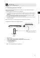
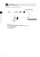
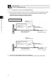

3. Connecting with the Controller
31
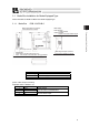
3.1 Brake Box Installation for Brake-Equipped Type
Attach the brake box RCB-110-RCLB-0 for brake-equipped type.
3.1.1 Brake Box RCB-110-RCLB-0
Items Specifications
Power Voltage 24V DC±10%
Power Current MAX2.5A (Approx. 110ms at brake release)
Weight Approx. 35g
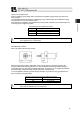
[Power / RDY Output Connector]
Applicable Cable : AWG24 to 16
Pin No. Signal name Contents
1 RDY+
2 RDY-
Ready contact
Open at brake overloaded alarm
3 +24V
4 0V
DC+24V Power Input
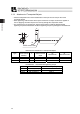
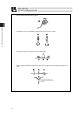
65
48
3
25
(1.8)
(1.8)
8.5
2.75
2-
φ
3.5
45
50.5
56
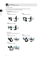
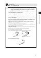
Brake Signal Output Connector
Connected to the controller
Power /
RDY Output Connector
LEDs display
•Green: RDY No alarm after power is on
•Red : ALM Brake overloaded alarm being generated
LEDs display
•Green:BK RLS
In brake release
•Yellow:RLS SIG
Output of the brake release signal
Brake Signal Output Connector
Connected to the Micro-cylinder