
User guide

2. ACON-C/CG, PCON-C/CG
42
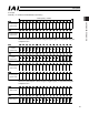
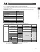
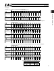
CompoNet
Channel (* “n” shows the node address of each axis.)
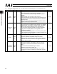
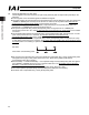
Zone boundary –
(upper word)
(lower word)
Zone boundary –
1word(1CH)=16bits
When the zone boundary is shown using the negative figure, it is expressed using the
complement of 2.
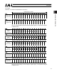
Acceleration
Deceleration
Pressing
Current
Limit Value
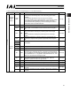
Control
Signal 1
Load current
threshold
(*3)
Control
Signal 2
(*1)
(*2)
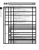
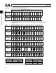
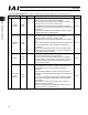
(*1) Signal assignment for b10 of n+14 (*2) Signal assignment for b7 and b6 of n+14
Symbol Symbol
Controller ACON PCON Controller ACON PCON
b10 - SMOD b7 MOD1 -
b6 MOD0 -
(*3) This is a dedicated function for PCON controllers. It is not available with ACON controllers.
ASO1
ASO0