
User guide

4. SCON-CA
172
CompoNet
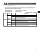
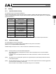
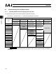
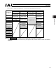
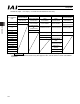
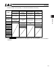
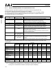
x SCON-CA output o PLC input (* “n” shows the node address of each axis.)
DO on the SCON-CA side and Output Data Register
Remote I/O Mode
Position / Simplified
Direct Value Mode
Half Direct Value
Mode
Full Direct Value
Mode
Remote I/O Mode 2
PLC output area
(CH)
Number of occupied
channels:1CH
Number of occupied
channels:4CH
Number of occupied
channels:8CH
Number of occupied
channels:16CH
Number of occupied
channels:6CH
n Port No.0 to 15 Port No.0 to 15
n㧗1
Current Position Current Position Current Position
Occupied area
n㧗2
Completed Position
No.
(simple alarm ID)
n㧗3 Status Signal
Command Current Command Current Current position
n㧗4
n㧗5
Current Speed Current Speed Command current
n㧗6 Alarm Code Alarm Code
n㧗7 Status Signal Occupied area
n㧗8
n㧗9
Force feedback
data
n㧗10
n㧗11
Total moving count
n㧗12
n㧗13
Total moving
distance
n㧗14 Status signal 1
n㧗15
Status signal 2
(Note) The Occupied area shows the area to be occupied with the operation mode setting.
Therefore, this area cannot be used for any other purpose. Also, exercise caution to avoid node address
duplication.