
User guide

3. SCON-CA/CFA
97
CompoNet
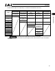
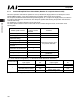
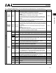
(1) PLC channel configuration (* “n” shows the node address of each axis.)
Parameter
No.84
PCON-CA/CFA
DI(Port No.)
PLC output CH
PCON-CA/CFA
DO(Port No.)
PLC input CH
0 0 to 15 n+0 0 to 15 n+0
(Note) Be careful of using duplicated node addresses.
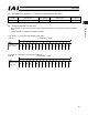
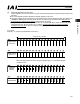
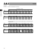
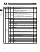
(2) I/O Signal Allocation for each Axis
The I/O signals of each axis consist of one input word (channel) and one output word (channel) in the I/O
areas.
x Each channel is controlled by ON/OFF bit signals.
(* “n” shows the node address of each axis.)PLC output
Channel
Controller input
port number
1 word (1CH) = 16 bits
(* “n” shows the node address of each axis.)PLC input
Channel
Controller output
port number
1 word (1CH) = 16 bits