
Owner's manual


5. SCON-CA
CC-Link
212
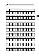
PLC Input (* “n” shows the head register address per each axis).
Address one word = 16 bits
RX (n+0) F E D C B A 9 8 7 6 5 4 3 2 1 0
Controller
Output
Port No.
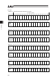
15
14
13
12
11
10
9
8
7
6
5
4
3
2
1
0
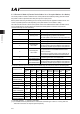
RWr (n+0) b15 b14 b13 b12 b11 b10 b9 b8 b7 b6 b5 b4 b3 b2 b1 b0
Current
Position
(Slave Word)
RWr (n+1) b15 b14 b13 b12 b11 b10 b9 b8 b7 b6 b5 b4 b3 b2 b1 b0
Current
Position
(Host Word)
When the current position is shown using thenegative figure, it is expressed using the complement of 2.
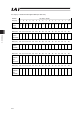
RWr (n+2) b15 b14 b13 b12 b11 b10 b9 b8 b7 b6 b5 b4 b3 b2 b1 b0
Force
Feedback
Data
(Slave Word)
RWr (n+3) b15 b14 b13 b12 b11 b10 b9 b8 b7 b6 b5 b4 b3 b2 b1 b0
Force
Feedback
Data
(Host Word)
When the force feedback data is shown using thenegative figure, it is expressed using the complement of 2.